
900 MHz WIRELESS DUAL BAND REPEATER
DoorKing Part Number
2332-080
Installation
Note:
DoorKing offers a 900 MHz Wireless Test Range Kit (P/N 1514-140) to allow easy testing of the wireless signal between
2 devices at chosen locations
BEFORE
installing the devices. The self-powered test kit measures the 900 MHz wireless signal
between 2 devices in
ANY
chosen locations. Ensuring a good signal can be achieved before installation occurs.
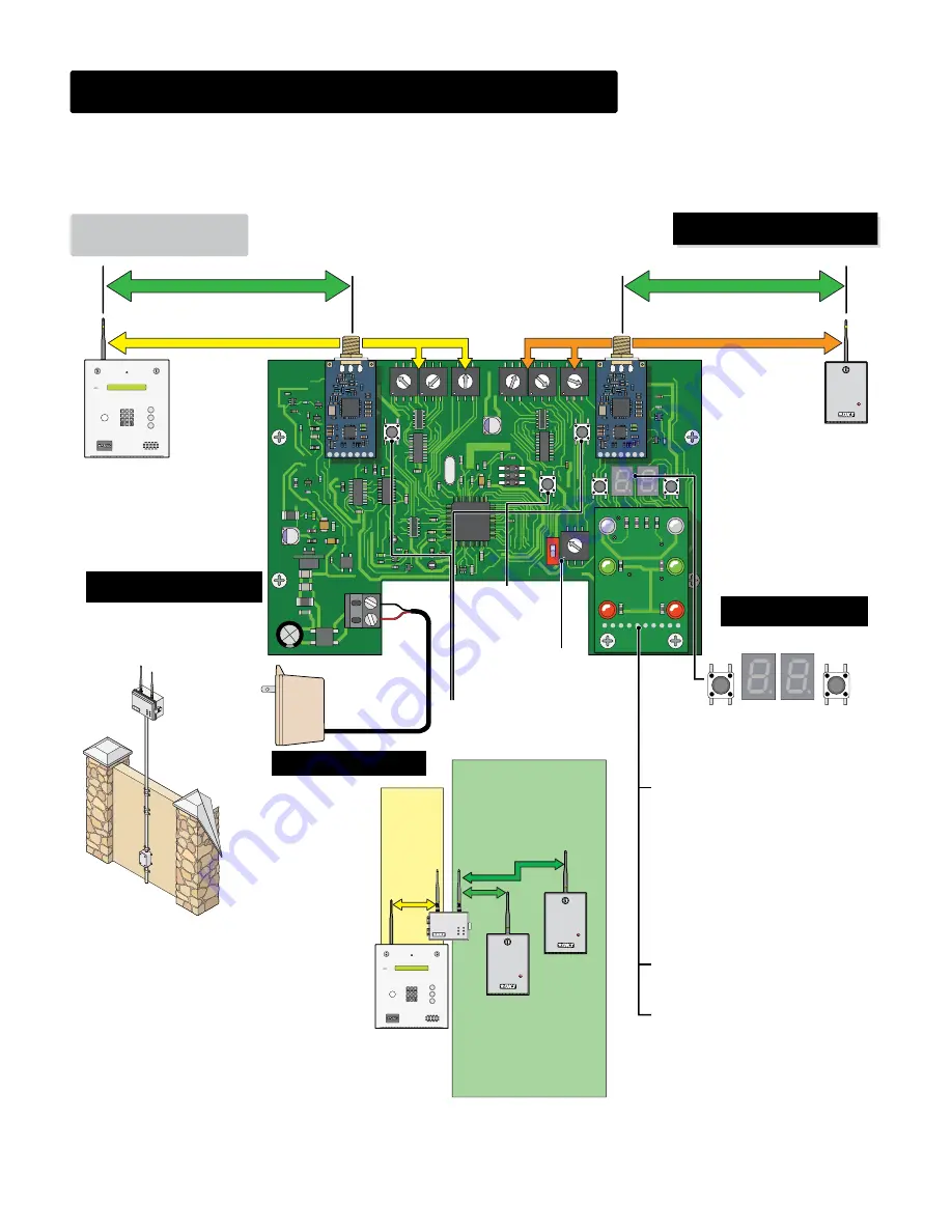
The 900 MHz wireless dual band repeater (DBR) extends the wireless communication range between an access control system (900 MHz wireless
baseboard) and 900 MHz wireless tracker expansion board. It gets installed between the wireless devices that are too far or obstructed from each
other to reliably communicate with each other. It will receive a signal sent to it and repeat that signal to the next wireless device. ONLY 1 DBR can
be used in the same communication line of a tracker expansion board. The signal range of a DBR is
Up to 1500 ft direct-line-of-sight
with no
signal interference. See “
900 MHz Wireless Baseboard Manual
” for complete access control system wireless setup information.
SX1276
SX1276
0
F
E
D
C
B
A
9
8
7
6
5
4
3
2
1
0
F
E
D
C
B
A
9
8
7
6
5
4
3
2
1
0
F
E
D
C
B
A
9
8
7
6
5
4
3
2
1
PROG
PROG
BASE
SIG
RESET
REMOTE
SIG
NET ID
BASE
CH
0
F
E
D
C
B
A
9
8
7
6
5
4
3
2
1
0
F
E
D
C
B
A
9
8
7
6
5
4
3
2
1
0
F
E
D
C
B
A
9
8
7
6
5
4
3
2
1
0
F
E
D
C
B
A
9
8
7
6
5
4
3
2
1
NET ID
REMOTE
CH
POWER
HEART BEAT
RF STRENGTH
RF SYNC
RF LOST
2373-010
BASE
REMOTE
ON
OFF
ADDRESS
ON
2332-010
V INPUT
+
-
Up to 1500 ft
Up to 1500 ft
0
4
5
6
1
2
3
7
8
9
CALL
Z
A
Power
Supply
12VDC
BASE
SIG
REMOTE
SIG
IMPORTANT:
Install the DBR
so the antenna is in a
location that is
NOT
surrounded by metal
and is in free air as
high as possible above
the ground. Minimum
15 ft above ground
recommended.
1/2” thick wall
PVC conduit
recommended
(not supplied).
Metal conduit
may interfere
with wireless
signal.
Base side communicates with the
wireless Baseboard of the 1830
series. The
CH
and
NET ID
of the
Base side MUST match the
CH
and
Net ID
of the Baseboard.
DO NOT
set Base side the same as
the Remote side.
TIP:
It is best to keep the
CH
s at least
2 numbers
away from
each other
if possible
for signal separation. This helps
eliminate interference between base side and remote side.
Remote side communicates
with the wireless Tracker
board. The
CH
and
NET ID
of
the Remote side MUST match
the
CH
and
Net ID
of the
Tracker board.
DO NOT
set Remote side the
same as the Base side.
Base Side
Remote Side
900 MHz
Wireless
Baseboard
Antenna
900 MHz
Wireless
Tracker Board
Example:
The wireless
baseboard
MUST be set to:
NET ID
: 2A
CH
: 1
Example:
The wireless
tracker board
MUST be set to:
NET ID
: 2C
CH
: 3
Power Transformer
18 GA. Wire 100 ft max
16 GA. Wire 200 ft max
Wire Polarity
Matters!
Black - NEG
Red
+ POS
Press
PROG
buttons after setting
the
CH
and
NET IDs
on
EACH
side.
Set
ADDRESS
to the
same as wireless
tracker board.
RESET Button
Resets board after
adjustments have
been made.
BASE SIG
Press to display
base side signal
strength.
REMOTE SIG
Press to display
remote side signal
strength.
RF STRENGTH LEDs (Base/Remote)
Off in normal operation. When signal is
displayed (press base/remote SIG button)
it is either green-good, yellow-weak or
red-NO. When signal is displayed, LED
blinks until signal is received, once
received, it stays lit.
Note:
Signal display is terminated if either
Base or Remote
PROGRAM
button is
pressed or the number of minutes is
reached as selected by the SIG button.
RF SYNC LEDs (Base/Remote)
Off in normal operation. Blinks green
everytime data is received over the air.
RF LOST LEDs (Base/Remote)
Off in normal operation. Blinks when no air
data is detected after six minutes and stays
lit after NO air data is received for 10
minutes.
NET ID
: 2A
CH
: 1
NET ID
: 2C
CH
: 3
Range testing is HIGHLY recommended
before FINAL installation.
Dual Band
Repeater Setup
See back page for an example.
Tracker
Baseboard
CH
s match
and
NET ID
s
match
and both are
unique
CH
s match
and
NET ID
s
match
and both are
unique
GREEN
YELLOW
0
4
5
6
1
2
3
7
8
9
CALL
Z
A
DBR
Tracker
DBR Note:
Typically up to 2
tracker expansion boards can
communicate with DBR. Up to
4 tracker expansion boards can
communicate with DBR in
LOW
activity applications.
Do Not Connect Power To A Receptacle
Controlled By A Switch.
2332-065 Issued 11-18
Version E


