background image

Copyright 2009 DoorKing, Inc. All rights reserved.

Copyright 2018 DoorKing

®

, Inc. All rights reserved.

Date Installed:

Installer/Company Name:

Phone Number:

Leave Manual with Owner 

Circuit Board
Serial Number
and Revision Letter:

Model Number

Installation/Owner’s Manual

90 Series

Telephone Entry and Access Control Systems

90 Series

90 Series

1837

1837

1837

1835

1835

1835

26, 30 and 31-Bit Wiegand Compatible

For 1837 circuit board:
1837-010 Revision Z or higher.

For 1835 circuit board:
1835-009 Revision Z or higher.

Download 

REMOTE ACCOUNT MANAGER

 Software 

FREE

 at: 


http://www.doorking.com/telephone/software

8 Line LCD Display

Single Line LCD Display

4

7

0

1

5

8

2

6

9

3

A

CALL

Z

Ad

ams J

Akins M
An

nese J

>Anderson

 H

Ap

plegate 

B

Aust

in D

Ba

lsbaugh B

Bass 

J

020
115
352

>CALL

656
078
221
321

4

7

0

1

5

8

2

6

9

3

A

CALL

Z

Ad

ams

 J

020

Conforms To UL STD 294 

Certified To CSA STD C22.2 # 205 

1835-067-A-9-18

Summary of Contents for 1837

Page 1: ... 1837 1835 1835 1835 26 30 and 31 Bit Wiegand Compatible For 1837 circuit board 1837 010 Revision Z or higher For 1835 circuit board 1835 009 Revision Z or higher Download REMOTE ACCOUNT MANAGER Software FREE at http www doorking com telephone software 8 Line LCD Display Single Line LCD Display 4 7 0 1 5 8 2 6 9 3 A CALL Z Adams J Akins M Annese J Anderson H Applegate B Austin D Balsbaugh B Bass J...

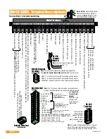
Page 2: ...r dial a phone number see 3 2 7 The Postal Switch is connected here Earth Ground Only See Section 2 1 3 Phone Line Connection 1 2 3 14 12 13 11 10 9 8 7 6 5 4 3 2 1 Aux Terminal Removable RS 232 Terminal Removable Elevator Control Terminal Non Removable Relay 0 Terminal Non Removable Note Connect to the Elevator Control Board 2348 010 See Elevator Control Board Manual 2348 065 for more info 100 ft...

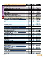
Page 3: ... 3 4 4 3 4 5 35 36 37 38 39 None 80 81 80 81 No factory setting No factory setting No factory setting No factory setting Programming Five Digit Device Codes Delete Device Codes Enabling Facility Codes Programming Facility Codes Section 3 6 Programming Device Codes 3 6 1 3 6 2 3 6 3 3 6 4 45 45 45 45 70 71 72 73 No factory setting No factory setting No factory setting No factory setting Programming...

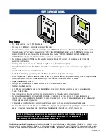
Page 4: ...Rev E and higher boards only allow the system to be used in areas requiring 10 and 11 digit dialing Three internal relays allow the system to control a main entry point plus two additional entry points System can be expanded to control up to 48 entry points in addition to the main entry point Expansion boards are required one for each additional entry point and are not included with the system Exp...

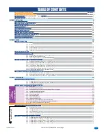
Page 5: ...TCP IP Converter Direct Connection to PC Data Transfer ONLY SECTION 3 PROGRAMMING 3 1 General Programming Information 3 1 1 Programming from a PC 3 1 2 Programming from the Telephone Entry System Keypad 3 1 3 System Memory Chip Identification 3 2 Setup Telephone Entry System for PC Programming 3 2 1 Master Code 3 2 2 Number of Area Codes Allowed 3 2 3 Call Up Operation when Interfacing with DoorKi...

Page 6: ...M OPERATING INSTRUCTIONS 5 1 Guest Instructions 5 2 Resident Instructions 5 2 1 Responding to a Guest Call 5 2 2 Using an Entry Code 5 3 System Administrator 5 3 1 Connecting to the Telephone Entry System from a Remote Location 5 3 2 Expansion Board Override HOLD OPEN Command 5 3 3 Relay Check 5 3 4 Time and Date Check 5 4 Miscellaneous Operating Instructions 5 4 1 Talk Time 5 4 2 Telephone Line S...

Page 7: ...The Load Number LN assigned to each terminal device denotes the percentage of the total load to be connected to a telephone loop which is used by the device to prevent overloading The termination on a loop may consist of any combination of devices subject only to the require ment that the sum of the load numbers of all the devices does not exceed 100 Notice DoorKing does not provide a power transf...

Page 8: ...ble to protect them from direct exposure to driven rain or snow whenever possible This telephone entry system contains a number of static sensitive components that can be damaged or destroyed by static discharges during installation or use Discharge any static prior to removing the circuit board from the lobby panel by touching a proper ground device Instruct the end user to read and follow these ...

Page 9: ...round device GREAT care must be taken after removing the components from the enclosure to protect them throughout the installation Carelessness on your part is NOT covered under warranty Make sure ALL dirt metal or wood debris is removed from inside the enclosure after mounting it A through cleaning of the enclosure is needed before re installing the components back into the system and wiring it A...

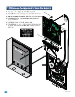
Page 10: ...ard by touching a proper ground device Faceplate Hinge Locknuts 1 Disconnect the two ribbon cables from the circuit board 2 Remove the two screws from the upper corners of the circuit board 3 GENTLY remove the circuit board by pulling it out of the main terminal 4 Remove the two screws from the main terminal and remove the ground wire locknut 5 Remove five 5 locknuts from the faceplate hinge 6 Rem...

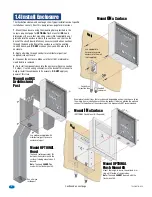
Page 11: ...stem is used to control a vehicular gate with an automatic gate operator the entry system must be mounted a minimum of six 6 feet away from the gate and gate operator or in such a way that a person cannot operate the entry system and touch the gate or gate operator at the same time OPTIONAL Flush Mount Kit P N 1814 200 OPTIONAL Hood Stainless Steel P N 1814 180 Black P N 1814 185 Back View Bottom ...

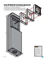
Page 12: ...s page for dimensions Use hardware supplied with architectural post to secure enclosure to post The hood sold separately fits between the enclosure and the surface it s being mounted on if desired Note The hood CANNOT be used with the flush mount kit Use appropriate hardware to secure enclosure to the wall not supplied Mount ONa Surface Mount INa Surface OPTIONAL Flush Mount Kit Required Mount to ...

Page 13: ...m ring into the rough in box Slide the enclosure in the trim ring and secure them all together with hardware included in the kit Rough In Box Trim Ring WARNING If this entry system is used to control a vehicular gate with an automatic gate operator the entry system must be mounted a minimum of six 6 feet away from the gate and gate operator or in such a way that a person cannot operate the entry s...

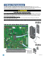
Page 14: ...he memory chip s with care the pins bend easily DO NOT install the memory chip s UPSIDE DOWN this will cause permanent damage to the chip s Be sure that the memory chip is seated correctly in the socket CAUTION 1830 Series Circuit Board Memory Chip s Location Dimple MUST be at the top of the chip Locked Release NC NO NO RING NC C ON SPK VOL FEED BACK RS 232 ELEVATOR 1 2 3 4 5 6 7 8 9 10 11 12 13 1...

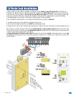
Page 15: ...ONLY when installing postal lock 3 Remove the two hex nuts from the postal lock mounting studs Mount postal lock on the studs and secure with the hex nuts When the lock is installed the pawl of the lock in the extended position is depressing the switch When the mail carrier inserts his key and turns the postal lock the pawl is withdrawn into the lock and the switch will activate the relay for the ...

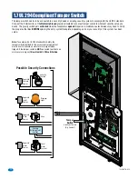
Page 16: ...vity Activated Dry Contact White White Possible Security Connections Security Camera Local Alarm System Separate Alarm Power Siren Warning Light Separate Siren Power Separate Light Power Separate Camera Power Existing Building Alarm System Note To comply with UL 294 Standard for Safety the tamper switch provided in this access control equipment must be set to activate an alarm or alarm signal when...

Page 17: ...n back of lighted keypad as shown Use longer screws that comes with kit Polarity Matters 16 AWG 200 Ft 18 AWG 100 Ft Output 12 VDC Power Wire Run Black Red Wire not supplied 0 4 5 6 1 2 3 7 8 9 CALL Z A 0 4 5 6 1 2 3 7 8 9 CALL Z A 1835 Camera Position 1837 Camera Position 1 8 OPTIONAL Internal Card Reader Installation Support Bar Logo Plate Important DO NOT power the camera with the telephone ent...

Page 18: ...plate Built in magnets will secure heater in place The heater gets VERY HOT DO NOT allow existing components or wires to come in contact with the metal heater housing Faceplate Attach the thermostat on the bottom inside of the cabinet as far from heater as possible DO NOT position the thermostat right next to the heater Built in magnets will secure thermostat in place Thermostat will automatically...

Page 19: ...t come into contact with the gate or gate operator when using this entry system If this unit has been installed closer to the automated vehicular gate do not proceed with any wiring until the unit has been moved and re installed so that it is in compliance with these instructions This telephone entry system contains a number of static sensitive components that can be damaged or destroyed by static...

Page 20: ... from being touched or electrical shock could occur Phone line surge suppressor within 10 ft of entry system Surge suppressor within 3 ft of ground source Phone Company PHONE LINE 1877 010 2 1 3 Grounding 2 1 4 Surge Suppression 2 1 5 Expansion Boards and Elevator Control 2 1 6 Ferrite Filter If Expansion Boards are being used with this system refer to the Installation and Wiring manual that came ...

Page 21: ...d strike time or dial a phone number see 3 2 7 The Postal Switch is connected here Earth Ground Only See Section 2 1 3 Phone Line Connection 1 2 3 14 12 13 11 10 9 8 7 6 5 4 3 2 1 Aux Terminal Removable RS 232 Terminal Removable Elevator Control Terminal Non Removable Relay 0 Terminal Non Removable Note Connect to the Elevator Control Board 2348 010 See Elevator Control Board Manual 2348 065 for m...

Page 22: ...d Input Relay 1 26 30 and 31 Bit Card Reader Input Use 6 conductor stranded with overall shield 18 20 22 or 24 gauge See section 2 1 2 Wiegand Input Relay 2 26 30 and 31 Bit Card Reader Input Use 6 conductor stranded with overall shield 18 20 22 or 24 gauge See section 2 1 2 PC Connection See sections 2 4 and 2 5 for wiring RS 232 Relay 1 Input Telephone Entry Systems Control up to 3 entry points ...

Page 23: ... Reader 6 9 Wiegand Card Reader 6 9 16 VAC 20 VA Ground 32 Ground 32 Blue 17 Red 10 Brown 19 Blue 17 Red 10 Brown 19 Black 27 White 28 Green 29 Black 27 White 28 Green 29 Door Lock or Gate Operator 25 26 Door Lock or Gate Operator 25 26 Relay 0 Main Door Gate IMPORTANT NOTE ONLY use circuit board 2358 010 Rev L or higher This access control equipment must be installed inside of a controlled protec...

Page 24: ...ate a specific RELAY 24 boards MAX for each relay The tracker expansion boards are pre programmed with many features but can be programmed for specific needs when desired See Tracker Expansion Board Manual 2358 065 for ALL programming options See DoorKing s web site and the instruction sheets with the wireless kits for complete installation information when using wireless communication 2 3 3 Track...

Page 25: ... Use P N 2334 080 DKS VoIP Connection Voice AND RS 232 for Data Connection Third Party Service see 2 4 2c Use Third Party VoIP Connection Voice Use P N 1830 185 for Data Connection DKS IM Server Modem Service see 2 4 3a Use IM Server Modem for Data Connection Use Telephone line for Voice Connection Third Party Service see 2 4 3b User supplied modem for Data Connection Use Telephone line for Voice ...

Page 26: ...D Your PC connected to the internet wired or wireless Phone Line Voice ONLY VoIP Analog Telephone Adapter PW R LN K A CT Ph on e DoorKing VoIP service and data transfer service is available for one low monthly fee without any long term contracts DoorKing VoIP service and data transfer service is available for one low monthly fee without any long term contracts Select you own VoIP service and data ...

Page 27: ...et 2 4 3a DoorKing IM Server Modem Connection Voice Data Transfer 2 4 2d DoorKing TCP IP Converter Mounting Position Phone Company SOFTWARE INSTALLED Internet IM Server Modem Note IM Server is NOT compatible with VoIP services Note You are responsible for the telephone line charges connected to the entry system 0 4 5 6 1 2 3 7 8 9 CALL Z A P1 P2 TCP IP Converter RS 232 to Internet Mount TCP IP con...

Page 28: ...r ONLY 1 2 3 4 5 6 RS 232 Terminal RS 232 Terminal Description Telephone Entry System Circuit Board Requires DoorKing RS 232 9 pin cable P N 1818 040 and RS 232 to USB Adapter P N 1815 037 to connect to a PC Board Pins Wire Color 1 2 3 4 5 6 DB 9 Pins 3 2 7 8 5 DB 25 Pins Board Function 2 3 4 5 7 Transmit Data Receive Data Request to Send Clear to Send Signal Ground Shell Not Used Red Black White ...

Page 29: ...nd R 2 are then designated as Tracker Expansion board command CMD relays with R 2 controlling Expansion boards 1 through 8 system relays 3 10 and R 1 controlling Expansion boards 9 through 16 system relays 11 18 The PRIMARY relay is the relay that a resident activates from their telephone after receiving a call from a visitor When Tracker Expansion boards or other wiegand devices are used with the...

Page 30: ...156 1835 157 1835 140 1835 141 1835 142 1835 143 1835 144 1835 145 1835 146 1835 147 System Memory 25 75 125 250 500 1000 2000 3000 Phone Number Capacity 25 75 125 250 500 1000 2000 3000 Name Capacity 25 75 125 250 500 1000 2000 3000 Entry Code Capacity 25 75 125 250 500 1000 2000 3000 Device Code Capacity 625 1875 3125 6250 8000 8000 8000 8000 Prior to using a PC to program this PC Programmable T...

Page 31: ... Press and enter your four digit MASTER CODE beep 2 Enter beep to turn the call up feature OFF Enter beep to turn the call up feature ON Special applications ONLY 3 Press together to end this programming sequence beeeeeep When elevator control is in use an access device such as a card reader must be installed in the elevator car to allow residents access to the floors in the building The time inte...

Page 32: ...ified in the security level screen then press beep 3 Press together to end this programming sequence beeeeeep The following programming sequence sets the switch input main terminals 4 and 6 to either activate a relay s or call the phone number programmed in directory code 0 00 000 or 0000 Refer to section 3 3 4 to determine which relay s will activate when the switch input is activated This featur...

Page 33: ...entry systems that have a smaller memory size less than 3000 with or without cards and anti pass back capability and all units are being managed by DKS Remote Account Manager Software with the Share Info feature The new 1830 chip specification MUST MATCH the older 1830 chip specifications or EXISTING programming conflicts will occur See section 3 1 3 for more information about 1830 memory specific...

Page 34: ...her programming steps in this manual SOFTWARE INSTALLED SOFTWARE INSTALLED PC s only NOT for use with MACs SOFTWARE INSTALLED The following programming sequence turns the LIVE Transaction viewing on your PC On or Off When turned ON all transactions can be viewed Real Time from your PC When turned OFF the transaction buffer must be downloaded before viewing the transaction history log The transacti...

Page 35: ...3 4 5 35 36 37 38 39 None 80 81 80 81 No factory setting No factory setting No factory setting No factory setting Programming Five Digit Device Codes Delete Device Codes Enabling Facility Codes Programming Facility Codes Section 3 6 Programming Device Codes 3 6 1 3 6 2 3 6 3 3 6 4 45 45 45 45 70 71 72 73 No factory setting No factory setting No factory setting No factory setting Programming the An...

Page 36: ...the entry system places a call to the resident The talk time can be set from 1 second up to 255 seconds 4 minutes 15 seconds and is entered as a three digit number in step 3 The talk time set here DOES NOT affect the telephone numbers that are programmed under directory codes 0 00 000 0000 and 1 01 001 0001 The talk time for these two directory code sets are factory set to the maximum Phone number...

Page 37: ...pen number code then press beep Example If you want a relay to have a momentary activation function only and you want that relay to momentary activate when the number 9 is pressed enter 9 If a function is not desired enter in place of a number Do not duplicate tone open numbers Example don t set relay 0 1 and 2 tone open numbers all to 9 4 Repeat steps 2 and 3 to set other relay tone open numbers ...

Page 38: ...press beep Three digit positions 1st digit position Relay 0 2nd digit position Relay 1 3rd digit position Relay 2 To activate a relay enter a 1 in a digit position To NOT activate a relay enter a 0 in a digit position Example entering 010 will cause only relay 1 to activate Entering 101 will cause both relay 0 and relay 2 to activate 3 Press together to end this programming sequence beeeeeep This ...

Page 39: ...ace clear the display if a mistake is made and a sequence to skip a name if there is a desire not to provide a name with a phone number A B C D E F G H I J K L M N O P Q R S T U V W X Y Z 0 1 2 3 4 5 6 7 8 9 Space Clear Skip Name Press The keypad on these telephone entry systems have all the letters of the alphabet the numbers 0 through 9 and a space key printed on it This allows the keypad to be ...

Page 40: ... the next block Note The factory default message was programmed from a PC therefore upper and lower case letters are displayed Example THANK YOU FOR VISITING OAKWOOD CONDOMINIUMS Block 1 Block 2 Block 3 1 2 3 4 5 6 7 8 9 10 11 12 13 14 15 16 17 18 19 20 T H A N K Y O U F O R V I S I T I N G O A K W O O D C O N D O M I N I U M S Block 1 Block 2 Block 3 1 2 3 4 5 6 7 8 9 10 11 12 13 14 15 16 17 18 1...

Page 41: ... Note The factory default message was programmed from a PC therefore upper and lower case letters are displayed Example PUSH A OR Z BUTTON TO FIND NAME ENTER CODE OR PUSH CALL Block 1 Block 2 Block 3 1 2 3 4 5 6 7 8 9 10 11 12 13 14 15 16 17 18 19 20 P U S H A O R Z T O F I N D N A M E E N T E R C O D E O R P Block 1 Block 2 Block 3 1 2 3 4 5 6 7 8 9 10 11 12 13 14 15 16 17 18 19 20 1 Press and en...

Page 42: ...rammed from a PC therefore upper and lower case letters are displayed Example WELCOME TO THE OAKWOOD CONDOMINIUMS PLEASE DRIVE CAREFULLY Block 1 Block 2 Block 3 Block 4 1 2 3 4 5 6 7 8 9 10 11 12 13 14 15 16 17 18 19 20 W E L C O M E T O T H E O A K W O O D C O N D O M I N I U M S P L E A S E D R I V E Block 1 Block 2 Block 3 Block 4 1 2 3 4 5 6 7 8 9 10 11 12 13 14 15 16 17 18 19 20 C A R E F U L...

Page 43: ...med from a PC therefore upper and lower case letters are displayed Example USE A Z TO FIND NAME OR NUMBER ENTER CODE ON KEYPAD BUSY PRESS ANY KEY TRY AGAIN Block 1 Block 2 Block 3 Block 4 1 2 3 4 5 6 7 8 9 10 11 12 13 14 15 16 17 18 19 20 U S E A Z T O F I N D N A M E O R N U M B E R E N T E R C O D E O N K E Y P A D B U S Y P R E S S A N Y K E Y T R Y A G A I N Block 1 Block 2 Block 3 Block 4 1 2...

Page 44: ... press again to enter the entire name into the directory If you make a mistake simply press to clear the display and start over Names cannot be more than 15 characters in length spaces count as a character Only upper case letters numbers spaces and a clear function in case you make a mistake can be programmed from the system keypad Press the 5 key one time to display J then press the key to enter ...

Page 45: ...is programming sequence the directory codes AND 7 digit phone numbers will be programmed into the system Be sure you have programmed the directory code length that you desire as described in 3 5 1 above Changing the directory code length after programming the telephone numbers will erase all the numbers and directory codes that have been programmed To program phone numbers that will need to use an...

Page 46: ... 10 digit calling requirements precede the three digit area code with Note 255 area codes are available on REV E and higher circuit boards REV D and lower boards only have 10 area codes 3 5 3 Programming Area Codes In this section phone numbers that are referenced to an area code pointer long distance and 10 digit dialing calls will be programmed with the directory code Be sure that the area code ...

Page 47: ... programmed to 3 5 5 Programming Names This programming sequence is used to delete a single phone number under a known directory code Proceed to 3 5 7 to delete the resident name after deleting the phone number 3 5 6 Deleting Individual Phone Numbers 1 Press and enter your four digit MASTER CODE beep 2 Enter the existing directory code section 3 5 2 or 3 5 4 that the phone number has been assigned...

Page 48: ...rogrammed under the entered directory code If the first digit is flashing this is the area code reference code and indicates that the number displayed is a long distance or 10 digit number 3 To display additional phone numbers press and repeat step 2 or proceed to step 4 to end programming 4 Press together to end this programming sequence beeeeeep If the telephone entry system is connected to a PB...

Page 49: ...ss and enter your four digit MASTER CODE beep 2 Enter the existing directory code section 3 5 2 or 3 5 4 that the desired device code has been assigned to 1 2 3 or 4 digits section 3 5 1 then press beep 3 Enter the desired five digit device code then press beep 4 Repeat steps 2 and 3 to delete additional desired device codes 5 Press together to end this programming sequence beeeeeep This program s...

Page 50: ...or relay 2 or any combination of relays by programming HI and LOW ranges for each relay Ranges between relays may overlap which will cause more than one relay to activate if this is desired For example if the low boundary for relay 0 and relay 1 is 2000 and the hi boundary is 3000 for relay 0 and 4000 for relay 1 then entry codes between 2000 and 3000 will activate both relays and entry codes betw...

Page 51: ...ce beeeeeep This programming step is used to allow all cards one move either in or out without causing an APB Violation to be recorded 3 8 2 Re Sync All Devices 1 Press and enter your four digit MASTER CODE beep 2 Press to Re Sync ALL devices or press to NOT Re Sync then press beeeeeep 3 The programming sequence will end itself after all cards have been re synced This programming step is used to r...

Page 52: ...tion 2 1 Expansion boards and elevator control and 2 2 Auxiliary Terminal see section 2 2 Relay 2 Jumper Normally Open NO Normally Closed NC see section 4 6 Relay 0 Terminal Normally Open NO Normally Closed NC Common C see section 2 2 Keypad Connector Master Code Switch see sections 3 2 1 and 4 4 Ring Pin Jumper see sections 3 1 and 4 5 Feedback Tone ON OFF Jumper see section 4 1 Speaker Volume se...

Page 53: ... volume may need to be decreased For louder microphone volume the speaker volume may need to be decreased 7 Normal setting for both speaker volume and microphone volume is about 1 2 8 After setting these adjustments place some test calls If feedback occurs microphone and or speaker volume will need to be reduced MIC VOL 3 2 1 FEED BACK 3 2 1 3 2 1 SPK VOL LCD display is adjusted at the factory and...

Page 54: ...jumper is set to AUTO from the factory Auto 1816 4 5 Ring Pin Jumper The ring pin jumper is labeled RING on the control board This jumper MUST be installed to allow the system to ALWAYS answer the calls placed to it If remote programming or remote relay operation is to be used the jumper MUST be installed on the pins Removing the jumper will cause the system to NEVER answer calls placed to it RING...

Page 55: ...ode assigned to the person they wish to visit 1835 System Guest use the A and Z buttons to locate the name in the directory Once the residents name is displayed the guest presses the CALL button and the system will connect to the resident s telephone The guest may also enter the directory code on the keypad to place the call 1837 System Guest use the A and Z buttons to locate the name in the direc...

Page 56: ...es or until it detects dial tone Some newer type telephones emit a short tone rather than a continuous tone when their keys are pressed This may cause the telephone entry system to not respond to the tone open number If this happens simply press the tone open number twice in rapid succession to open the door or gate If a resident is using a rotary dial telephone they will grant access to their gue...

Page 57: ...4 Hang up 5 To release the override hold command and return the system to normal operation repeat steps 1 through 4 In step 3 enter the DEACTIVATE tone number in place of the HOLD OPEN tone number 5 3 2 Expansion Board Override HOLD OPEN Command The telephone entry system can be called and a check can be made to determine if any of the relays in the system are in a hold open mode This check can be...

Page 58: ...umbers in place of a seven digit telephone number To do this enter the extension number and fill the remaining spaces with the key in the phone number programming step For example if the PBX system uses four digit extensions and you want to program extension 2217 as a phone number in step 3 of section 3 5 2 press 2 2 1 7 beep If the PBX system requires you to dial 9 to obtain an outside line and y...

Page 59: ... Noise on the phone line will cause problems with the entry system 3 Be sure that the entry system case is properly grounded 4 Be sure that the telephone wires are twisted 5 A hum on the system indicates that the phone line or 16 5 VAC power lines may be grounded Check to be sure that the phone lines or power lines are not shorted to ground 6 Check the 16 5 VAC system power Be sure that the transf...

Page 60: ...ped off the postal switch Be sure that the relay has been programmed for postal switch input 3 3 4 Forgetting to press first Re program the entry code ranges 3 7 3 Re program relay 0 low and high ranges 3 7 3 Re program relay 1 low and high ranges 3 7 3 Entry codes will not activate relay 2 Re program relay 2 low and high ranges 3 7 3 Master code switch is in the ON position 4 4 The system CALL UP...

Page 61: ...ending the information to the entry system If NO data appears on the display the wiegand devices are NOT functioning 5 Press to cancel the wiegand test mode beeeeeep 6 1 2 Wiegand Test This programming sequence is designed for troubleshooting the elevator control board s that may be connected to the telephone entry system This sequence will take approximately four 4 minutes to complete and will ch...

Page 62: ...ator control board s This sequence will allow you to program different methods by which the telephone entry system will hang up if a resident denies a guest access by hanging up their telephone rather than pressing the key to terminate the call Factory setting is 1 dial tone detect ON 1 Press and enter your four digit MASTER CODE beep The LCD display will show 0 N 1 DT 2 SIL 3 BTH 0 BOTH OFF Unit ...

Page 63: ...a over IP Phone Number or System ID Number is programmed the DKS Data over IP is automatically turned ON If there is NOT a valid 10 digit system phone number or system ID number in memory the system will emit three 3 short beeps Beep Beep Beep 6 1 9 Turn DKS Data over IP OFF or ON 1 Press and enter your four digit MASTER CODE beep 2 Press beep to turn OFF OR beep to turn ON 3 Press together to end...

Page 64: ... having a maximum of 64 floors Battery 12 volt 8 amp hour gel cell provides stand by power during power interruptions P N 1801 008 Telephone Test Set Includes clips cord and carrying case P N 1800 050 RS 232 Cable RS 232 cable with DB 9 connector on one end and wires on the other end Use this cable to program the entry system from a PC using RS 232 communications instead of the modem P N 1818 040 ...

Page 65: ... BAT 1NO 1NC 1C 2RY 2C A Z IMC 5VDC IMD SPKR COM MIC PSW CGND PHONE 1998 010 DOORKING 1835 009 TONE ON TONE OFF P1 P2 DOORKING 1896 019 1835 Wiring Schematic White White Purple White Green Green Blue Ground Lighted Keypad Lighted A Z Call Buttons Red Microphone Phone Line LCD Display Single Line Display LCD Interface Board Speaker Postal Lock Switch Gray Orange Yellow Brown Red White RELAY 0 RELAY...

Page 66: ... CUTOFF CONTRAST 8 LINE DISPLAY DOORKING 1892 010 DOORKING 1837 010 3 2 1 SINGLE LINE DISPLAY CONTRAST 1998 010 DOORKING 1896 012 TONE ON TONE OFF P1 P2 LCD Interface Board 1837 Wiring Schematic White White Purple White White White Green Green Blue Ground Red Microphone UL 294 Tamper Switch Phone Line LCD Display 8 Line Display Postal Lock Switch Speaker RELAY 0 RELAY 2 RELAY 1 Lighted Keypad Ligh...

Page 67: ...n 3 7 1 if they are used DEVICE CODE is the resident s unique device code section 3 6 1 if access control devices Transmitters cards etc are used ELEVATOR USE ONLY Remote Account Manager Software must be used SEC LEVEL Security Level FL Floor ER Elevator Reference Number Name Resident Log Sheet Example ER FL SEC LEVEL ELEVATOR USE DEVICE CODE ENTRY CODE DIRECTORY CODE PHONE NUMBER AAC Smith John 3...

Page 68: ...es section 3 5 3 7 1 2 255 Area Codes Page 1 027 028 029 030 031 032 033 034 035 036 037 038 039 040 041 042 043 044 045 046 047 048 049 050 051 052 053 054 055 056 057 058 059 060 061 062 063 064 065 066 067 068 069 070 071 072 073 074 075 076 077 078 079 080 081 082 083 084 085 086 087 088 089 090 091 092 093 094 095 096 097 098 099 100 101 102 103 104 105 106 107 108 109 110 111 112 113 114 115...

Page 69: ... 170 171 172 173 174 175 176 177 178 179 180 181 182 183 184 185 186 187 188 189 190 191 192 193 194 195 196 197 198 199 200 201 202 203 204 205 206 207 208 209 210 211 212 213 214 215 216 217 218 219 220 221 222 223 224 225 226 227 228 229 230 231 232 233 234 235 236 237 238 239 240 241 242 243 244 245 246 247 248 249 250 251 252 253 254 255 000 131 132 133 134 135 136 137 138 139 140 141 142 143...

Page 70: ...1835 067 A 9 18 66 Name ER FL SEC LEVEL ELEVATOR USE DEVICE CODE ENTRY CODE DIRECTORY CODE PHONE NUMBER AAC 7 2 Resident Information Make additional copies of this table as needed ...

Page 71: ...ESS to your guest press _____ on your touch tone telephone The telephone entry system will respond with a confirmation tone indicating that the door or gate is opening and will automatically disconnect itself Some newer telephones emit a very short duration tone when the number is pressed If your telephone does this you may have to press the GRANT ACCESS NUMBER twice in rapid succession to open th...

Page 72: ... Manual DoorKing Inc 120 S Glasgow Avenue Inglewood California 90301 U S A Phone 310 645 0023 Fax 310 641 1586 26 30 and 31 Bit Wiegand Compatable Download REMOTE ACCOUNT MANAGER Software FREE at http www doorking com telephone software 90 Series 90 Series 90 Series 1835 067 A 9 18 ...

Reviews: