© 2015 DORMA
USA: DORMA DRIVE, DRAWER AC, REAMSTOWN, PA 17567 PHONE: (800) 523-8483 (717) 336-3881 FAX: (717) 336-2106
EMAIl: archdw@dorma-usa.com WEbSITE: dorma-usa.com
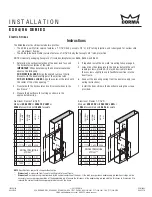
1. Determine the vertical centerline of the door lock face and
the horizontal centerline of the latch.
IMPORTANT: When determining the horizontal centerline
observe the following:
FOR MORTISE LOCKS: Align the angled ramps of the lip
bracket with the deadlock trigger of the mortise latch.
FOR CYLINDRICAL LOCKS: Align the center of the latch with
the center of the strike opening.**
2. Transfer both the horizontal and vertical centerlines to the
doorframe.**
3. Prepare the doorframe for cutting as shown in the
appropriate drawing.
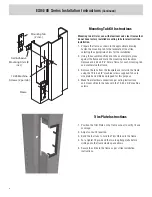
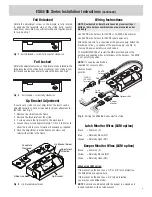
4. If required, install the ‘no weld’ mounting tabs per page 4.
5. Attach the strike faceplate to the lip bracket with the self-
tapping screws provided. (It may be desirable to leave
these screws slightly loose to facilitate insertion into the
doorframe.
6. Connect the incoming wiring from the power supply (see
wiring instructions).
7. Install the door strike in the doorframe using the screws
provided.
Instructions
E
K
B
A
F
M
G
C
G
D
R
X
CL
CL
M
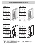
MEASUREMENT
FRACTIONA
l
INCHES
DECIMA
l
INCHES
METRIC
mm
A 1-1/4 1.250 31.75
b 4-7/8 4.875 123.83
C 3-3/8 3.375 85.73
D 1-3/16 1.188 30.16
E 3/8
.375 9.53
F
1/8*
.125* 3.18*
G 1-11/16 1.688 42.86
Vertical Vertical Vertical
X C/l
C/l
C/l
Door Door Door
R 5/32 0.156 3.97
K 4-1/8 4.125 104.78
M 12-24 —
—
Vertical Centerline
of Door**
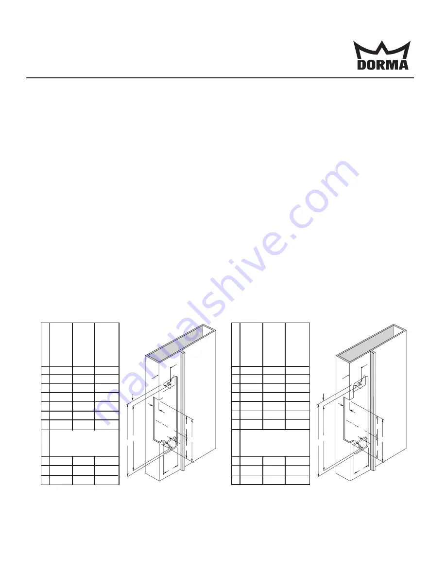
Aluminum Frames 1-3/16”D
Modular ES86 FSV or ES86 FSV LKM or
ES86 U assembled with 86S4 faceplate
Aluminum Frames 1-1/16”D
Modular ES84 FSV or ES84 FSV LKM or
ES84 U assembled with 86S4 faceplate
E
K
B
A
F
M
G
C
G
D
R
X
CL
CL
M
MEASUREMENT
FRACTIONA
l
INCHES
DECIMA
l
INCHES
METRIC
mm
A 1-1/4 1.250 31.75
b 4-7/8 4.875 123.83
C 3-3/8 3.375 85.73
D 1-3/32 1.094 27.78
E 3/8
.375 9.53
F
1/8*
.125* 3.18*
G 1-11/16 1.688 42.86
Vertical Vertical Vertical
X C/l
C/l
C/l
Door Door Door
R 5/32 0.156 3.97
K 4-1/8 4.125 104.78
M 12-24 —
—
Vertical Centerline
of Door**
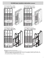
NOTE: Specifications subject to change without notice.
* Dimension F is measured from face of mounting tab to face of frame.
** Dimension X on the drawing is determined by the vertical centerline of the door. If the latch incorporates a deadlocking pin additional steps will be
necessary to ensure proper operation of the deadlocking pin. Measure the thickness of the deadlocking pin and add this thickness to Dimension X to
relocate the vertical centerline an appropriate distance on the frame.
ISES84/86
08281220
PCN14085
R09/15TG
The ES84/86 electric strikes include two profiles:
• The ES84 (Low Profile) version features a 1-1/16”D body, accepts 1/2” or 5/8” latch projection, and is designed for narrow stile
(i.e., aluminum) frames.
• The ES86 (Standard Profile) version features a 1-3/16”D body that accepts 3/4” latch projection.
NOTE: Universal packaging (faceplate ‘U’) includes faceplate sizes 86S4, 86S4S, and 86S7.
Electric Strikes
I N S T A l l A T I O N
E S 8 4 / 8 6 S E r i E S


