background image

W h e r e   I n n o v a t i o n   F l o w s

www.wildenpump.com

EOM

Engineering

Operation &

Maintenance

WIL-11210-E-15

REPLACES WIL-11210-E-14

P400 / PX400

Advanced

 Series

Metal Pumps

Summary of Contents for Wilden Advanced P400

Page 1: ...W h e r e I n n o v a t i o n F l o w s www wildenpump com EOM Engineering Operation Maintenance WIL 11210 E 15 REPLACES WIL 11210 E 14 P400 PX400 Advanced Series Metal Pumps ...

Page 2: ...um Performance Curves Rubber Fitted 7 TPE Fitted 7 Reduced Stroke PTFE Fitted 8 Full Stroke PTFE Fitted 8 Ultra Flex Fitted 9 P400 Stainless Steel Performance Curves Rubber Fitted 10 TPE Fitted 10 Reduced Stroke PTFE Fitted 11 Full Stroke PTFE Fitted 11 Ultra Flex Fitted 12 Suction Lift Curves P400 Aluminum 13 P400 Stainless Steel Alloy C 14 Operating Principle 16 How to Use this EMS Curve 17 PX40...

Page 3: ...y pressure CAUTION The process fluid and cleaning fluids must be chemically compatible with all wetted pump components Consult Chemical Resistance Guide E4 CAUTION Do not exceed 82 C 180 F air inlet temperature for Pro Flo X models CAUTION Pumps should be thoroughly flushed before installing into process lines FDA and USDA approved pumps should be cleaned and or sanitized before being used CAUTION...

Page 4: ... EZ INSTALL Santoprene Two Orange Dots NES NEOPRENE Green Dot NEU NEOPRENE ULTRA FLEX PUS POLYURETHANE Clear TEU PTFE w EPDM BACK UP White TNU PTFE W NEOPRENE BACK UP White TSS FULL STROKE PTFE W SANIFLEX BACK UP TSU PTFE W SANIFLEX BACK UP White TWS FULL STROKE PTFE W WIL FLEX BACK UP VTS VITON White Dot VTU VITON ULTRA FLEX WFS WIL FLEX Santoprene Orange Dot XBS CONDUCTIVE BUNA N Two Red Dots ZG...

Page 5: ...developed in the liquid chamber and manifold of the pump These same hydraulic forces lift the discharge valve ball off its seat while the opposite discharge valve ball is forced onto its seat forcing fluid to flow through the pump discharge The movement of diaphragm A toward the center of the pump creates a vacuum within liquid chamber A Atmos pheric pressure forces fluid into the inlet manifold o...

Page 6: ...5 K 244 9 6 L 206 8 1 M 152 6 0 N 170 6 7 P 10 0 4 DIN FLANGE R 110 DIA 4 3 DIA S 150 DIA 5 9 DIA T 18 DIA 0 7 DIA ANSI FLANGE R 98 DIA 3 9 DIA S 127 DIA 5 0 DIA T 16 DIA 0 6 DIA REV D DIMENSIONS ITEM METRIC mm STANDARD inch A 381 15 0 B 89 3 5 C 277 10 9 D 530 20 8 E 295 11 6 F 89 3 5 G 277 10 9 H 275 10 8 J 224 8 8 K 203 8 0 L 176 7 0 M 11 0 4 DIN FLANGE N 150 DIA 5 9 DIA P 110 DIA 4 3 DIA R 18 ...

Page 7: ... N 206 8 1 P 152 6 0 R 170 6 7 S 10 0 4 DIN FLANGE T 150 DIA 5 9 DIA U 110 DIA 4 3 DIA V 18 DIA 0 7 DIA ANSI FLANGE T 127 DIA 5 0 DIA U 98 DIA 3 9 DIA V 16 DIA 0 6 DIA REV B DIMENSIONS ITEM METRIC mm STANDARD inch A 381 15 0 B 89 3 5 C 277 10 9 D 530 20 8 E 280 11 0 F 49 1 9 G 131 5 2 H 309 12 2 J 520 20 5 K 83 3 3 L 275 10 8 M 224 8 8 N 176 7 0 P 203 8 0 R 11 0 4 DIN FLANGE S 150 DIA 5 9 DIA T 11...

Page 8: ...40 psig requires 3 5 bar 51 psig and 20 Nm3 h 12 scfm air consumption Caution Do not exceed 8 6 bar 125 psig air supply pressure Flow rates indicated on chart were determined by pumping water For optimum life and performance pumps should be specified so that daily operation parameters will fall in the center of the pump s performance curve Height 594 mm 23 4 Width 343 mm 13 5 Depth 340 mm 13 4 Shi...

Page 9: ... 0 57 L 0 15 gal 1 Max Flow Rate 329 lpm 87 gpm Max Size Solids 7 9 mm 5 16 1 Displacement per stroke was calculated at 4 8 bar 70 psig air inlet pressure against a 2 1 bar 30 psig head pressure Example To pump 114 lpm 30 gpm against a discharge pressure head of 2 8 bar 40 psig requires 3 8 bar 55 psig and 46 Nm3 h 27 scfm air consumption Caution Do not exceed 8 6 bar 125 psig air supply pressure ...

Page 10: ...and 20 Nm3 h 12 scfm air consumption Caution Do not exceed 8 6 bar 125 psig air supply pressure P E R F O R M A N C E P400 STAINLESS STEEL RUBBER FITTED Flow rates indicated on chart were determined by pumping water For optimum life and performance pumps should be specified so that daily operation parameters will fall in the center of the pump s performance curve Height 528 mm 20 8 Width 384 mm 15...

Page 11: ...ight 316 Stainless Steel 35 kg 77 lb Alloy C 38 kg 83 lb Air Inlet 13 mm 1 2 Inlet 38 mm 1 1 2 Outlet 38 mm 1 1 2 Suction Lift 5 2 m Dry 17 0 8 8 m Wet 29 0 Displacement Stroke 1 10 L 0 29 gal 1 Max Flow Rate 307 lpm 81 gpm Max Size Solids 4 8 mm 3 16 1 Displacement per stroke was calculated at 4 8 bar 70 psig air inlet pressure against a 2 1 bar 30 psig head pressure Example To pump 114 lpm 30 gp...

Page 12: ...n Caution Do not exceed 8 6 bar 125 psig air supply pressure P400 STAINLESS STEEL FULL STROKE PTFE FITTED Flow rates indicated on chart were determined by pumping water For optimum life and performance pumps should be specified so that daily operation parameters will fall in the center of the pump s performance curve Height 528 mm 20 8 Width 384 mm 15 1 Depth 295 mm 11 6 Ship Weight 316 Stainless ...

Page 13: ...p Weight 316 Stainless Steel 35 kg 77 lb Alloy C 38 kg 83 lb Air Inlet 13 mm 1 2 Inlet 38 mm 1 1 2 Outlet 38 mm 1 1 2 Suction Lift 5 2 m Dry 17 0 8 5 m Wet 28 0 Displacement Stroke 0 76 L 0 20 gal 1 Max Flow Rate 269 lpm 71 gpm Max Size Solids 4 8 mm 3 16 1 Displacement per stroke was calculated at 4 8 bar 70 psig air inlet pressure against a 2 1 bar 30 psig head pressure Example To pump 170 lpm 4...

Page 14: ...tion atmospheric pressure and pipe friction loss all affect the amount of suction lift your pump will attain Suction lift curves are calibrated for pumps operating at 305 m 1 000 above sea level This chart is meant to be a guide only There are many variables that can affect your pump s operating characteristics The number of intake and discharge elbows viscosity of pumping fluid elevation atmosphe...

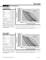
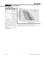
Page 15: ...PX400 M E T A L P X 4 0 0 P E R F O R M A N C E WIL 11210 T 05 ...

Page 16: ...hat exceeds previous industry standards Pro Flo XTM Operating Principle S e c t i o n 5 B Turning the dial changes the relationship between air inlet and exhaust porting Each dial setting represents an entirely different flow curve Pro Flo X pumps are shipped from the factory on setting 4 which is the highest flow rate setting possible Moving the dial from setting 4 causes a decrease in flow and a...

Page 17: ...n this case 9 8 scfm Step 2 Determining flow and air X Factors Locate your discharge pressure 40 psig on the verti cal axis of the EMS curve Figure 2 Follow along the 2 8 bar 40 psig horizontal line until intersecting both flow and air curves for your desired EMS setting in this case setting 2 Mark the points where the EMS curves inter sect the horizontal discharge pressure line After locating you...

Page 18: ...psig discharge pressure After locat ing this point on the flow curve draw a verti cal line downward until reaching the bottom scale on the chart and identify the flow rate In our example it is 38 6 lpm 10 2 gpm This is the setting 4 flow rate Observe the loca tion of the performance point relative to air consumption curves and approximate air consumption value In our example setting 4 air consumpt...

Page 19: ...different than the flow point plotted in example 2 1 Af ter estimating or interpolating this point on the curve draw a vertical line downward un til reaching the bottom scale on the chart and identify the air X Factor Figure 7 Step 2 Determine air consumption Multiply your setting 4 air consumption 14 scfm value by the air X Factor obtained above 0 40 to deter mine your actual air consumption In s...

Page 20: ...MS setting and discharge pressure the X factor is used as a multi plier with the original values from the setting 4 performance curve to calculate the actual flow and air consumption values for that spe cific EMS setting Note you can interpolate between the setting curves for operation at intermediate EMS settings EXAMPLE A PX400 aluminum Rubber fitted pump operating at EMS setting 4 achieved a fl...

Page 21: ...5 while the air consumption was reduced by 49 thus providing increased efficiency For a detailed example for how to set your Ems see beginning of performance curve section caution Do not exceed 8 6 bar 125 psig air supply pressure The Efficiency Management System EMS can be used to optimize the performance of your Wilden pump for specific applications The pump is delivered with the EMS adjusted to...

Page 22: ...EMS setting and discharge pressure the X factor is used as a multi plier with the original values from the setting 4 performance curve to calculate the actual flow and air consumption values for that spe cific EMS setting Note you can interpolate between the setting curves for operation at intermediate EMS settings EXAMPLE A PX400 aluminum PTFE fitted pump operating at EMS setting 4 achieved a flo...

Page 23: ... setting 4 performance curve to calculate the actual flow and air consumption values for that spe cific EMS setting Note you can interpolate between the setting curves for operation at intermediate EMS settings EXAMPLE A PX400 aluminum Full Flow PTFE fitted pump operating at EMS setting 4 achieved a flow rate of 265 lpm 70 gpm using 136 Nm 3 h 80 scfm of air when run at 6 2 bar 90 psig air inlet p...

Page 24: ... 66 while the air consumption was reduced by 80 thus providing increased efficiency For a detailed example for how to set your Ems see beginning of performance curve section caution Do not exceed 8 6 bar 125 psig air supply pressure The Efficiency Management System EMS can be used to optimize the performance of your Wilden pump for specific applications The pump is delivered with the EMS adjusted ...

Page 25: ... achieved a flow rate of 178 lpm 47 gpm using 82 Nm 3 h 48 scfm of air when run at 5 5 bar 80 psig air inlet pressure and 3 4 bar 50 psig discharge pressure See dot on performance curve The end user did not require that much flow and wanted to reduce air consumption at his facility He determined that EMS setting 2 would meet his needs At 3 4 bar 50 psig discharge pressure and EMS setting 2 the flo...

Page 26: ...mption was reduced by 77 thus providing increased efficiency For a detailed example for how to set your Ems see beginning of performance curve section caution Do not exceed 8 6 bar 125 psig air supply pressure The Efficiency Management System EMS can be used to optimize the performance of your Wilden pump for specific applications The pump is delivered with the EMS adjusted to setting 4 which allo...

Page 27: ...ng 85 Nm 3 h 50 scfm of air when run at 3 6 bar 52 psig air inlet pressure and 2 1 bar 30 psig discharge pressure See dot on performance curve The end user did not require that much flow and wanted to reduce air consumption at his facility He determined that EMS setting 3 would meet his needs At 2 1 bar 30 psig discharge pressure and EMS setting 3 the flow X factor is 0 88 and the air X factor is ...

Page 28: ...psig discharge pressure See dot on performance curve The end user did not require that much flow and wanted to reduce air consumption at his facility He determined that EMS setting 1 would meet his needs At 1 4 bar 20 psig discharge pressure and EMS setting 1 the flow X factor is 0 45 and the air X factor is 0 23 see dots on EMS curve Multiplying the original setting 4 values by the X factors prov...

Page 29: ... air consumption was reduced by 53 thus providing increased efficiency For a detailed example for how to set your Ems see beginning of performance curve section caution Do not exceed 8 6 bar 125 psig air supply pressure The Efficiency Management System EMS can be used to optimize the performance of your Wilden pump for specific applications The pump is delivered with the EMS adjusted to setting 4 ...

Page 30: ...ltra Flex Diaphragms Reduced Stroke PTFE Diaphragms Full Stroke S U C T I O N L I F T C U R V E S WILDEN PUMP ENGINEERING LLC 28 PX400 Performance Suction lift curves are calibrated for pumps operating at 305 m 1 000 above sea level This chart is meant to be a guide only There are many variables that can affect your pump s operating characteristics The number of intake and discharge elbows viscosi...

Page 31: ...ume can be estimated by counting the number of strokes per minute and then multiplying the figure by the displacement per stroke MUFFLER Sound levels are reduced below OSHA specifications using the standard Wilden muffler Other mufflers can be used to further reduce sound levels but they usually reduce pump performance ELEVATION Selecting a site that is well within the pump s dynamic lift capabili...

Page 32: ...stop the pump from operating in an emergency situation simply close the shut off valve user supplied installed in the air supply line A properly functioning valve will stop the air supply to the pump therefore stopping output This shut off valve should be located far enough away from the pumping equipment such that it can be reached safely in an emergency situation This illustration is a generic r...

Page 33: ...ms and unscheduled downtime In addition accurate records make it possible to identify pumps that are poorly suited to their applications T R O U B L E S H O O T I N G Pump will not run or runs slowly 1 Ensure that the air inlet pressure is at least 0 4 bar 5 psig above startup pressure and that the differential pressure the difference between air inlet and liquid discharge pressures is not less th...

Page 34: ...e and air lines Drain the pump by turning it upside down and allowing any fluid to flow into a suitable container Be aware of any hazardous effects of contact with your process fluid NOTE The model photographed for these instructions incorporates rubber diaphragms balls and seats Models with PTFE diaphragms balls and seats are the same except where noted Step 1 Please note alignment marks on liqui...

Page 35: ...m the liquid chambers Step 6 Remove the inlet valve balls and valve seats from the inlet manifold and inspect for nicks gouges chemical attack or abrasive wear Step 7 Using a 9 16 wrench remove the liquid chamber from the center section Step 8 The liquid chamber should be removed to expose the diaphragm and outer piston Rotate center section and remove opposite liquid chamber Step 9 Using 2 adjust...

Page 36: ...gm assembly can be disassembled Step 11 To remove diaphragm assembly from shaft secure shaft with soft jaws a vise fitted with plywood plastic or other suitable material to ensure shaft is not nicked scratched or gouged Using an adjustable wrench remove diaphragm assembly form shaft P U M P D I S A S S E M B L Y ...

Page 37: ...zardous effects of contact with your process fluid The Wilden P400 and PX400 metal pumps utilize a revolutionary Pro Flo air distribution system Proprietary composite seals reduce the co efficient of friction and allow the P400 and PX400 to run lube free Constructed of acetal polypropylene or aluminum the Pro Flo air distribution system is designed to perform in on off non freezing non stalling to...

Page 38: ...ly Seals are not sold separately Step 6 Remove pilot sleeve retaining snap ring on both sides of center section with snap ring pliers A I R V A L V E C E N T E R S E C T I O N D I S A S S E M B L Y Step 7 Remove pilot spool sleeve from center section Step 8 Using an O ring pick gently remove the O ring from the opposite side of the notched end on one side of the pilot spool Gently remove the pilot...

Page 39: ...D I S A S S E M B L Y S U B M E R S I B L E P R O F L O X Step 1 Install a 1 4 NPT pipe plug 00 7010 08 into the pilot spool bleed port located at the front of the center block Step 2 Next install an optional submersible air valve gasket 04 2621 52 The submersible air valve gasket can be purchased as a spare part or included with the purchase of a new Pro Flo X pump Non Submersible Submersible ...

Page 40: ...Pistons All 54 2 N m 40 ft lb SHAFT SEAL INSTALLATION PRE INSTALLATION Once all of the old seals have been removed the inside of the bushing should be cleaned to ensure no debris is left that may cause premature damage to the new seals INSTALLATION The following tools can be used to aid in the installation of the new seals Needle Nose Pliers Phillips Screwdriver Electrical Tape Wrap electrical tap...

Page 41: ...N O T E S ...

Page 42: ...ultra Flex Fitted E x p l o d E d V i E w All CirClEd pArt idEntiFiErs ArE inCludEd in rEpAir Kits see section 9 WildEn PUmP EnginEEring llC 48 Wil 11210 E 14 T K 23 21 20 22 25 24 S e c t i o n 8 E x PL o d E d V I E w P A RT s L I s TI n g P400 ALuMInuM Rubber TPE PTfE ultra flex fitted E x PL o d E d V I E w WILDEn PUMP EngInEERIng LLC 48 WIL 11210 E 13 20 22 21 25 reDUCeD sTrOke PTFe FITTeD 24...

Page 43: ...0 03 04 3890 03 18 Air Chamber Pro Flo Bolted 2 04 3681 01 04 3681 01 19 Screw HSFHS 3 8 16x1 8 71 6250 08 71 6250 08 20 Shaft Pro Flo 1 04 3800 03 700 04 3820 03 700 Shaft Pro Flo Ultra Flex 1 N A 04 3830 03 700 21 Shaft Stud 2 08 6150 08 04 6150 08 22 Inner Piston 2 04 3700 01 700 04 3752 01 Inner Piston Ultra Flex 2 N A 04 3760 01 700 23 Diaphragm Primary 2 Diaphragm Full Stroke PTFE Primary 2 ...

Page 44: ...a Flex Fitted E x p l o d E d V i E w All CirClEd pArt idEntiFiErs ArE inCludEd in rEpAir Kits see section 9 WildEn PUmP EnginEEring llC 50 Wil 11210 E 14 T K 29 35 34 31 32 33 30 29 35 34 31 32 33 30 24 23 21 20 22 25 E x PL o d E d V I E w P A RT s L I s TI n g P400 sTAInLEss sTEEL Rubber TPE PTfE ultra flex fitted E x PL o d E d V I E w WILDEn PUMP EngInEERIng LLC 50 WIL 11210 E 13 FULL sTrOke ...

Page 45: ... 3685 01 18 Screw HSFHS 3 8 16 x 1 8 71 6250 08 71 6250 08 71 6250 08 71 6250 08 19 Retaining Ring 2 04 3890 03 04 3890 03 04 3890 03 04 3890 03 20 Shaft Pro Flo 1 04 3800 03 700 04 3800 03 700 04 3820 03 700 04 3820 03 700 Shaft Ultra Flex 1 N A N A 04 3830 03 700 04 3830 03 700 21 Shaft Stud 2 08 6150 08 08 6150 08 04 6150 08 04 6150 08 Shaft Stud Ultra Flex 2 N A N A 04 6152 08 04 6152 08 22 In...

Page 46: ... d V i E w p A r t s l i s t i n g All CirClEd pArt idEntiFiErs ArE inCludEd in rEpAir Kits see section 9 WildEn PUmP EnginEEring llC 52 Wil 11210 E 14 T K 19 17 16 18 21 20 Px400 ALuMInuM Rubber TPE PTfE ultra flex fitted E x PL o d E d V I E w E x PL o d E d V I E w P A RT s L I s TI n g ALL CIRCLEd PART IdEnTIfIERs ARE InCLudEd In REPAIR kITs see section 9 WILDEn PUMP EngInEERIng LLC 52 WIL 112...

Page 47: ...7 Shaft Stud 2 08 6150 08 04 6150 08 Shaft Stud Ultra Flex 2 N A N A 18 Piston Inner 2 04 3700 01 700 04 3752 01 Piston Inner Ultra Flex 2 N A 04 3760 01 700 19 Diaphragm 2 Diaphragm Full Stroke PTFE Primary 2 04 1040 55 N A 20 Diaphragm Back Up 2 N A Diaphragm Full Stroke PTFE Back Up 2 N A 21 Piston Outer 2 04 4552 01 04 4600 01 Piston Outer Ultra Flex 2 N A 04 4560 01 22 Seat Valve 4 04 1125 01...

Page 48: ... d E d V i E w p A r t s l i s t i n g All CirClEd pArt idEntiFiErs ArE inCludEd in rEpAir Kits see section 9 WildEn PUmP EnginEEring llC 54 Wil 11210 E 14 T K 5 4 1 2 3 9 7 12 34 33 11 8 10 6 20 19 17 16 18 21 Px400 sTAInLEss sTEEL Rubber TPE PTfE ultra flex fitted E x PL o d E d V I E w E x PL o d E d V I E w P A RT s L I s TI n g WILDEn PUMP EngInEERIng LLC 54 WIL 11210 E 13 ALL CIRCLEd PART Id...

Page 49: ...Ultra Flex 1 N A N A N A 04 3830 03 700 04 3830 03 700 04 3830 03 700 17 Shaft Stud 2 08 6150 08 08 6150 08 08 6150 08 04 6150 08 04 6150 08 04 6150 08 Shaft Stud Ultra Flex 2 N A N A N A 04 6152 08 04 6152 08 04 6152 08 18 Piston Inner 2 04 3700 01 700 04 3700 01 700 04 3700 01 700 04 3752 01 04 3752 01 04 3752 01 Piston Inner Ultra Flex 2 N A N A N A 04 3760 01 700 04 3760 01 700 04 3760 01 700 ...

Page 50: ...y C pumps WILDEn PUMP EngInEERIng LLC 58 WIL 11210 E 13 WildEn PUmP EnginEEring llC 58 Wil 11210 E 14 S e c t i o n 9 E l A s t o m E r o p t i o n s S e c t i o n 9 E L A s T o M E R o PTI o n s P400 PX400 meTAL MATERIAL dIAPHRAgMs 2 uLTRA fLEx dIAPHRAgMs 2 REduCEd sTRokE bACkuP dIAPHRAgMs 2 fuLL sTRokE bACkuP dIAPHRAgMs 2 VALVEbALLs 4 VALVEsEATs ALuM 4 VALVE sEATs ss ALLoyC 4 VALVEsEAT o RIngs A...

Page 51: ...ve Seats 4 P N Neoprene 04 1020 51 04 1080 51 50 04 1120 51 50 Buna N 04 1020 52 04 1080 52 50 04 1120 52 50 EPDM 04 1020 54 04 1080 54 50 04 1120 54 50 Viton 04 1020 53 04 1080 53 50 04 1120 53 50 E L A S T O M E R O P T I O N S WIL 11210 E 15 49 WILDEN PUMP ENGINEERING LLC ...

Page 52: ...N O T E S ...

Page 53: ...N O T E S ...

Page 54: ...N O T E S ...

Page 55: ...comes first Failure due to normal wear misapplication or abuse is of course excluded from this warranty Since the use of Wilden pumps and parts is beyond our control we cannot guarantee the suitability of any pump or part for a particular application and Wilden Pump and Engineering LLC shall not be liable for any consequential damage or expense arising from the use or misuse of its products on any...

Page 56: ...ackmer com FLUID DYNAMICS POLYMER BLENDING SYSTEMS fluiddynamics1 com GRISWOLD CENTRIFUGAL PUMPS griswoldpump com MAAG FILTRATION PLASTIC MANUFACTURING PROCESSING FILTRATION maag com MAAG INDUSTRIAL PUMPS GEAR SCREW PUMPS maag com MAAG PUMP SYSTEMS EXTRUSION PUMPS SYSTEMS maag com MOUVEX ECCENTRIC DISC PUMPS VANE PUMPS COMPRESSORS mouvex com NEPTUNE DIAPHRAGM METERING PUMPS POLYMER SYSTEMS MIXERS ...

Reviews: