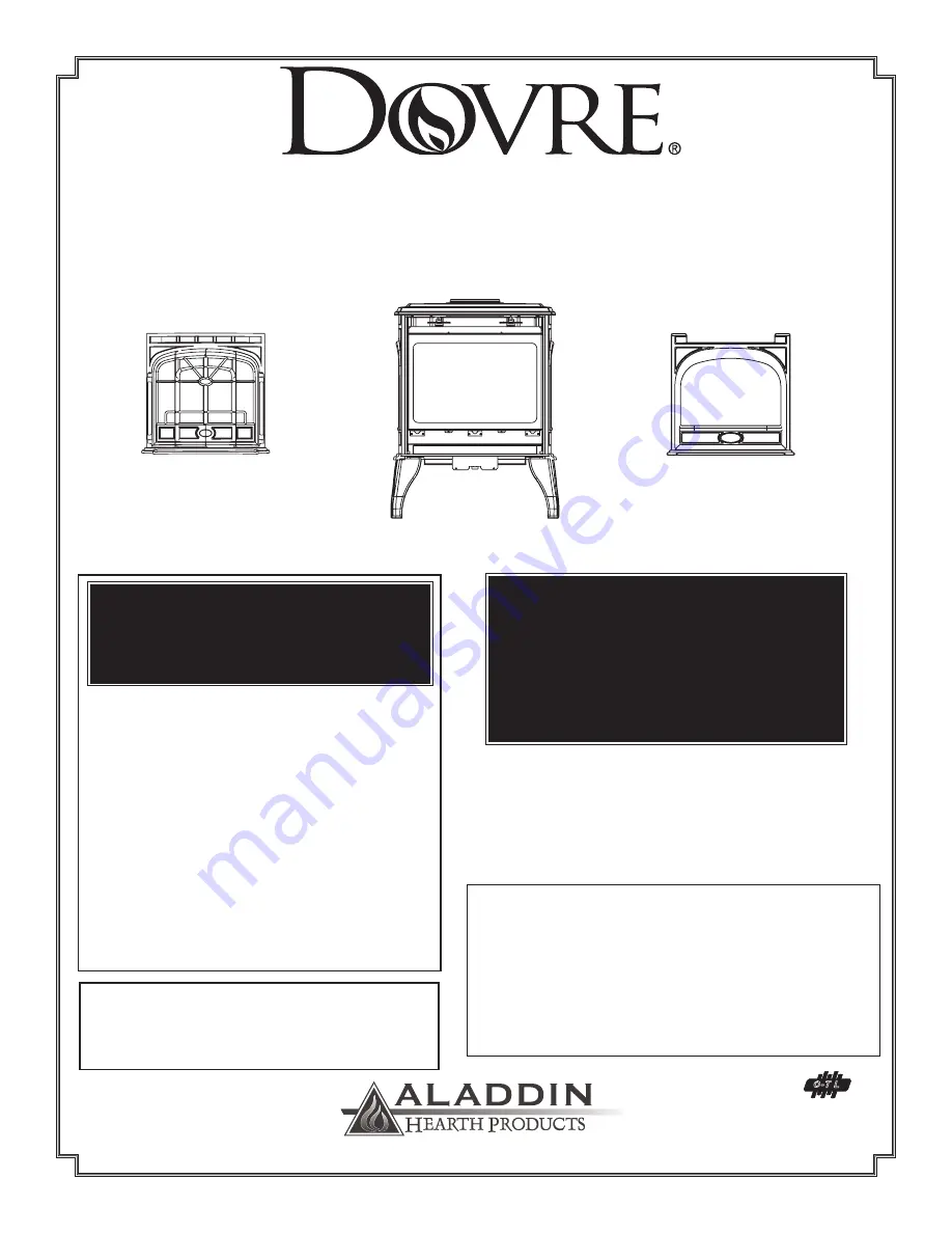
background image

SAPPHIRE DV425TR 

DIRECT VENT ROOM HEATER

OWNER’S MANUAL 

AND INSTALLATION INSTRUCTIONS

This Manual must be used for installation of the 

DV425TR Gas-Fired Room Heater and retained by the 

homeowner for operating and maintenance instructions.

WARNING!

Improper  installation, adjustment, alteration, 

service  or  maintenance  can  cause  injury  or 

property damage.  Refer to this Manual.  For 

assistance or additional information, consult 

a  qualified  installer, service  agency  or  the 

gas supplier.

This Heater may be installed with a Vertical

or Horizontal Direct Vent Termination System.

FOR YOUR SAFETY

The appliance area must be kept clear and free 

from combustible materials, gasoline and other 

flammable vapors and liquids.

-Do not store or use gasoline or other flammable     

vapors and liquids in the vicinity of this or any other 

appliance.
-WHAT TO DO IF YOU SMELL GAS
•    Do not try to light any appliance.
•    Do not touch any electrical switch; do not use any 

phone in your building.

•    Immediately  call  your  gas  supplier  from  a  neigh-

bor’s  phone.    Follow  the  gas  supplier’s  instruc-

tions.

•    If you cannot reach your gas supplier, call the fire 

department.

-Installation and service must be performed by a qual-

ified installer, service agency or the gas supplier.

WARNING!  

If the information in this Manual is not fol-

lowed exactly, a fire or explosion may result 

causing property damage, personal injury or 

loss of life.

This appliance may be installed in an aftermarket, 

permanently located, Manufactured (Mobile) Home, 

where not prohibited by Local Codes.

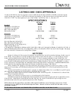
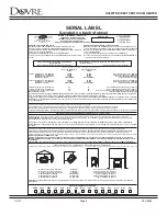
This appliance is only for use with the type of fuel 

indicated on the Rating Plate.  This appliance is not 

convertible for use with other gases, unless a certi-

fied Conversion Kit is used.

1445 North HIghway

Colville, WA 99114

A Division of Hearth Technologies Inc.

           addinhearth.com

                ahpfireup.com

#250-5533                02/2001

(FRONTS SOLD SEPARATELY)

O-T L

Tested and 

Listed by

Beaverton

Oregon USA

OMNI-Test Laboratories, Inc.

C

Quartet Front

Solitaire Front

Summary of Contents for SAPPHIRE DV425TR

Page 1: ...appliance Do not touch any electrical switch do not use any phone in your building Immediately call your gas supplier from a neigh bor s phone Follow the gas supplier s instruc tions If you cannot reach your gas supplier call the fire department Installation and service must be performed by a qual ified installer service agency or the gas supplier WARNING If the information in this Manual is not f...

Page 2: ...16 Thermostat Installation Remote Control 17 Grill Cover Installation 17 VENTING General Venting Instructions 18 Installation Methods Notes 19 Safety Precautions for the Installer 19 Simpson DuraVent Parts List 20 Installation Methods 22 Horizontal Installation Termination Requirements 26 Vent Graph 27 Vertical Installation Using GS Series Pipe 33 Roof Pitch Table 35 Cathedral Ceiling Installation...

Page 3: ... or the Canadian Installation Code CAN CGA 149 Manufactured Home or Mobile Home installation may occur only after the home is site located and must conform with the Manufactured Home Construction and Safety Standard Title 24 CFR Part 3280 or when such a standard is not applicable the Standard for Manufactured Home Installations ANSI INCSBCS A225 1 or Standard for Gas Equipped Recreational Vehicles...

Page 4: ... Efficacité Thermique 84 NG blower on avec ventilateur allumé 82 LP blower on avec ventilateur WARNING IMPROPER INSTALLATION ADJUSTMENT ALTERATION SERVICE OR MAINTENANCE CAN CAUSE INJURY OR PROPERTY DAMAGE REFER TO THE OWNER S INFORMATION MANUAL PROVIDED WITH THIS APPLIANCE FOR ASSISTANCE OR ADDITIONAL INFORMATION CONSULT A QUALIFIED INSTALLER SERVICE AGENCY OR THE GAS SUPPLIER AVERTISSEMENT UNE I...

Page 5: ...lammable liquids in the vicinity of the appliance If the flame becomes sooty dark orange in color or extremely tall DO NOT operate the appliance Contact your dealer and arrange for servicing immediately DO NOT operate the appliance if it is not operating properly in any manner Contact your dealer for assistance Open viewing glass for servicing only Operate the appliance in accordance with the inst...

Page 6: ...ding inspector for code requirements in your area Run thermostat lines to TH TPTH connectors on valve if applicable see page 17 Set unit in place and install venting per your installation requirements Install logset embers mineral wool and lava rock See instructions on page 14 of this manual Connect the gas line See page 44 Plug in blower if purchased Leak test gas line to manual shut off valve Se...

Page 7: ...NS 22 1 8 14 5 8 8 28 5 8 21 1 2 17 1 2 21 1 2 14 3 8 C L 22 1 4 14 5 8 8 DOVRE 425 T R Dimensions Rear Vent NOTE Diagrams show heater equipped with optional Blower part 844 9030 NOTE If heater is equipped with Hearth Legs Kit center line dimension is reduced by 3 ...

Page 8: ... 100 mm C Corner of stove top to side wall 1 152 mm D Minimum Alcove Height 54 1372 mm E Maximum Alcove Depth 36 914 mm F Minimum Alcove Width 36 915 mm HEARTH A non combustible hearth pad is not required However the floor beneath the stove must be stable level and strong enough to support the stove without a tipping hazard A A E A B C D F A C Minimum clearances required from combustible construct...

Page 9: ... Include 1 Front Face 2 Hinged Doors 2 Gold plated button head hinge pins 1 Bolt 2 washers Instructions continue for completion of the Quartet Doors ship attached to the face If they have been removed follow instructions 2 3 to replace 2 Install one door at a time Slide bottom hinge rod into lower hinge box hole on face See Figure 2 3 Place washer on top of door hinge Line up hole in door hinge an...

Page 10: ...late on back shield and discard See Fig 1 2 Remove rear outer flue cover plate with damper adjustment plate attached ensure that gaskets and grommet stay in place 3 Remove inner flue cover plate set aside A 2 At the TOP of stove with exceptions noted 4 Lift out cast insert piece on top 5 Remove outer flue collar and set aside See Fig 3 Ensure that gasket is intact if not high temperature silicone ...

Page 11: ...tall damper adjustment plate a set spacer in place b align adjustment plate c set screw into spacer and tighten See Fig 7 11 Re install outer flue collar on rear of stove See Fig 8 12 Install rear vent cover plate supplied with kit on back shield 13 Install top cast insert NOTE A grill cover plate is shipped with the stove This plate may be placed beneath the top grill See page 17 for installation...

Page 12: ...MS IMPORTANT NOTE The orifice supplied with the GAS conversion kit is for TOP VENT MODELS ONLY For vertical to horizontal venting conver sion the correct orifice is supplied WITH THE REAR VENT CONVERSION KIT 6 Re install burner plate First slide burner tube into shutter and over holes Secure plate with screws 7 Re install log burner pan Slide vertically into the back of firebox and then place hori...

Page 13: ...pilot injector with the one supplied in the conversion kit 35 for Propane 62 for Natural Gas NOTE The injector is ONLY replaced if you are con verting to another gas It is not replaced for a change from top to rear vent 6 Replace pilot hood snapping into position 7 Remove main burner orifice using a 5 8 wrench 8 Replace orifice with the proper size as indicated below for your gas type and venting ...

Page 14: ...t the rubber gasket D is properly positioned and install the new HI LO pressure regulator assembly to the valve using the new screws E supplied with the kit Tighten screws securely Reference torque 25 in lb 4 Install the enclosed identification label F to the valve body where it can be seen 5 Re install burner plate First slide burner tube into shut ter and over holes Secure plate with screws 6 Re...

Page 15: ...r the pins at the rear of burner pan See white circles in Fig 2 2 Set Left and Right Partial Logs with butt end towards side of stove firebox over the left and right side pins on burner pan Fig 3 3 Locate the pin hole on the bottom of the right and left twigs and situate them over the white pins located on Rear Log Fig 4 IMPORTANT Lava rock must only be placed in the recessed area to the front and...

Page 16: ...the switch wires and piezo wire at rear of stove Note This blower utilizes a snapdisc to control ON and OFF operation When the correct temperature is reached the blower will automatically turn ON Use the rheostat knob to adjust the fan to High or Low to suit your preferences FIG 4 FIG 1 FIG 2 Blower mounting bracket beneath stove as seen from front Ensure these wires are BEHIND the mounting bracke...

Page 17: ...Turn the manual switch on the control panel to OFF GRILL COVER INSTALLATION Top grill cover is shipped with the stove and is an optional use item It may be used with rear or top venting Primarily its purpose is to hide the interior of the top of the stove from being viewed through the top grill piece Its use will also increase the efficiency of the blower if a blower is installed on the stove To p...

Page 18: ...e to combustible requirements which may vary from one installation to another Do not extend the venting system in excess of the distance prescribed in these manufacturer s installation instructions This gas appliance must not be connected to a chimney flue serving a separate solid fuel burning appliance INSTALLATION PRECAUTIONS The Dovre DV425TR is an engineered product that has been designed and ...

Page 19: ...uired for vertical installations measure the distance from the stove flue outlet to the ceiling the ceiling thickness the vertical rise in an attic or second story and allow for sufficient vent height above the roofline Refer to the vertical vent termination tables on page 35 for this information For two story applications fire stops are required at each floor level If an offset is needed in the a...

Page 20: ...Termination Cap One 90 Black Elbow Wall Thimble 24 Black Pipe 11 14 5 8 Adjustable Vent 982 14 Snorkle 985 Horizontal Termination Cap Highwind 909B Retrofit Adjustable Chimney Connector Retrofit Chimney Connector Plate 950 VSS Vinyl Siding Standoff Shield 991 High Wind Vertical Termination Cap 3951 Round Ceiling Support Wall Thimble Trim Kit Polished Brass 3960 Cathedral Ceiling Support Trim Kit P...

Page 21: ...ponents Description HHW2 Horizontal High Wind Cap recommended for optimal performance HHW2K Horizontal Kit One 90o Black Elbow Wall Thimble 24 Black Pipe 11 14 5 8 Adjustable Vent HHW2 Termination Cap RHVK Snorkle Kit 844 8920 with Dura Vent part s 911B and 940 HTI VENTING PARTS LIST cont ...

Page 22: ...for installation instructions and requirements On horizontal terminations use only Dura vent Part 985 or Hearth Technologies Inc Part HHW2 INSTALLATION METHODS Type A Up Out Installations for Top Vent Configurations Type B Rear Vent Installations for Use With Rear Vent Kit see Parts Accessories pg 57 for conversion kit and pgs 20 21 for venting components WALL THIMBLE COVER PIPE LENGTH 844 8920 SN...

Page 23: ...3 FIG 2 VERTICAL TERMINATION Refer to pages 32 37 for installation instructions and requirements VERTICAL TERMINATION CAP STORM COLLAR FLASHING FIRESTOP PIPE LENGTH SUPPORT BOX On vertical terminations use only Dura vent Part 991 INSTALLATION METHODS cont ...

Page 24: ...33 FIG 3 CLASS A METAL CHIMNEY USA only Refer to pages 38 39 for installation instructions and requirements INSTALLATION METHODS cont TERMINATION CAP PART 991 EXISTING METAL CHIMNEY SYSTEM TOP ADAPTOR FLASHING 4 FLEX PIPE RETRO CONNECTOR DIRECT VENT PIPE ...

Page 25: ...t Configurations Type B Hearth Rear Vent Installations for Use With Rear Vent Kit see Parts Accessories pg 57 for conversion kit and pgs 20 21 for venting components Chimney Liner Termination Cap Part 923GK Co Axial to Co Linear Connector Part 923GCL Stove with Rear Vent Conversion Kit Part 844 8920 installed 3 FLEX LINER PIPE LENGTH OPTIONAL 45 Elbow 14 Pipe Length Max Wall Depth 10 1 Clearance f...

Page 26: ...um Clearance to nonmechanical air supply inlet to building or the combustion air inlet to any other appliance K 72 1 8m minimum Clearance to a mechanical air supply air inlet L 84 2 1m minimum Clearance above paved sidewalk or a paved driveway located on public property M 12 30cm minimum Clearance under veranda porch deck or balcony N 6 152 mm minimum Clearance to outside corner A vent shall not t...

Page 27: ...he allowable horizontal run to 9 3 1 2 elbows x 3 6 15 max 6 9 max Notes The maximum horizontal vent run is 15 4 57m when the vertical vent rise is 10 3 05m The minimum horizontal vent run is 12 305mm Minimum wall thickness is 4 102mm Maximum wall thickness is 20 508mm Horizontal sections require a 1 4 6mm rise for every 12 305mm of horizontal travel Exterior Vent Diameter 6 5 8 177mm Inner Vent D...

Page 28: ...ends of pipes and fittings are designed to slide straight onto the male ends of adjacent pipes and fittings by orienting the four pipe indentations so they match and slide into the four entry slots on the male ends see Fig 5 below Push the pipe sections completely together then twist lock one section clockwise approximately one quarter turn until the two sections are fully locked The female lockin...

Page 29: ...ns If the snorkel termination must be installed below grade i e basement application proper drainage must be provided to prevent water from entering the snorkel termination Do not backfill around snorkel termination Step 3 With the adapter and pipe attached to the stove slide the stove into its correct location maintaining minimum clearance to combustibles Mark the wall for a 10 x 10 254mm x 254mm...

Page 30: ...o brick concrete or other types of sidings 2 If you are using Simpson Dura vent termination cap 985 on a building with vinyl siding a vinyl siding standoff Simpson Dura vent Part 950 should be installed between the vent cap and the exterior wall Figure 8 Attach the vinyl siding standoff to the horizontal vent termination The vinyl siding standoff prevents excessive heat from possibly melting the v...

Page 31: ... vent pipe extend into the vent cap a sufficient distance so as to result in a minimum pipe overlap of 11 4 32mm Secure the connection between the vent pipe and the vent cap by attaching the two sheet metal strips extending from the vent cap assembly into the outer wall of the vent pipe Use the two sheet metal screws provided to connect the strips to the pipe section Figure 9 HORIZONTAL INSTALLATI...

Page 32: ...ical rise of the venting system and any maximum horizontal offset limitations All offsets must fall within the set parameters of the vent graph located on page 27 NOTE Maximum vertical rise allowable is 35 10 7m Figure 10 NOTE Maximum number of 45 elbows permitted for a vertical installation is eight provided their installation does not decrease maximum vertical rise as specified by Vent Graph on ...

Page 33: ...eiling to the position of the stove flue exit and mark the location where the vent will penetrate the ceiling Drill a small hole at this point Next drop a plumb bob from the roof to the hole previously drilled in the ceiling and mark the spot where the vent will penetrate the roof Determine if ceiling joists roof rafters or other framing will obstruct the venting system You may wish to relocate th...

Page 34: ...ve the roofline The galvanized finish is desirable above the roofline due to its higher corrosion resistance NOTE 1 If an offset is necessary in the attic to avoid obstructions it is important to support the vent pipe every 3 91 4cm to avoid excessive stress on the elbows and possible separation Wall straps are available for this purpose page 32 Figure 11 2 Whenever possible use 45 elbows instead ...

Page 35: ...ining rooflines steep pitched roofs and other similar factors can result in poor draft or down drafting In these cases increasing the vent height may solve this problem VERTICAL INSTALLATION cont Fig 15 Dimension H Obtained From Table 1 TABLE 1 MINIMUM HEIGHT ROOF PITCH FEET METERS Flat to 7 12 1 0 30 Over 7 12 to 8 12 1 5 0 46 Over 8 12 to 9 12 2 0 61 Over 9 12 to 10 12 2 5 0 76 Over 10 12 to 11 ...

Page 36: ... occupied areas above the first floor including closets and storage spaces which the vertical vent passed through must be enclosed The enclosure may be framed and sheetrocked with standard construction materials however refer to these installation instructions for the minimum allowable clearance between the outside of the vent pipe and the combustible surfaces of the enclosure Do not fill any of t...

Page 37: ... the support box both vertically and horizontally with a level Temporarily tack the support box in place through the inside walls and into the roof sheathing Step 5 Using tin snips cut the support box from the top corners down to the roofline and fold the resulting flaps over the roof sheathing Figure 18 Before nailing it to the roof run a bead of non hardening mastic around the top edges of the s...

Page 38: ...tionally sound and clean Step 1 Remove existing chimney cap Step 2 Measure the distance from the top of the chimney to the bottom of the ceiling support box add 3 75mm to this measurement and cut a section of 4 100mm flex pipe to that length the flex should be extended to its nominal length Step 3 Connect the end of the flex pipe section to the underside of the top adapter SDV 985K 986K or 987K us...

Page 39: ...tep 5 Pull the flexpipe down through the ceiling support box until it protrudes approximately 3 76mm Connect the flex pipe to the retro connector SDV 909B and attach with sheet metal screws Step 6 Push the flex pipe back up into the ceiling support box center the retro connector and attach it to the support box with sheet metal screws Step 7 The connection between the appliance and the retro conne...

Page 40: ...y wall cut and frame a 10 254mm square opening in the wall centered around the 6 152mm masonry opening If there is sheet rock only no studs in front of the masonry the 10 254mm opening is still needed but does not need to be framed This allows the retro connector to mount directly on the masonry and provide the correct clearances to combustibles see Figure 22 VERTICAL INSTALLATION cont INSTALLATIO...

Page 41: ...y to allow for connection to the termination kit Step 5 Connect the flex liner to the top adapter using three 3 sheet metal screws see Figure 19 page 44 Step 6 Feed the flex liner through the flashing into the chimney Carefully feed the flex liner down the chimney to the bottom and out the opening in the masonry wall forming an angle to line up the flex liner with the vent opening on the appliance...

Page 42: ...the coupler by using four 4 sheet metal screws for each side Figure 24 Step 8 Secure the top adapter to the flashing Use three 3 sheet metal screws through the side of the top adapter into the flange on the flashing Figure 25 Twist lock the high wind termination cap SDV 991 on to the top adapter VERTICAL INSTALLATION cont INSTALLATION INTO AN EXISTING MASONRY CHIMNEY cont USA ONLY Fig 24 HIGH WIND...

Page 43: ...or in order to extend through the opening in the wall thimble cover Step 11 The connection between the appliance and the retro connector may be completed with sections of direct vent pipe WARNING If any other appliances have been previously attached to this masonary flue or an open fireplace etc all openings into flue should be sealed properly It is very important that there is only one appliance ...

Page 44: ...r will have a label stating that the unit has been converted to propane Connect the gas line at the 3 8 pipe connector on the valve at the back of stove See illustration on the next page We recommend connecting the stove with an approved flex gas line If flex gas lines are not approved in your area you cannect a hard pipe to the gas hookup You must supply a manual shutoff valve in a visible locati...

Page 45: ...ed and 3 that the total gas load for the residence does not exceed the amount supplied The supply regulator the regulator that attaches directly to the residence inlet or to the propane tank should supply gas at the suggested input pressure listed above Contact the local gas supplier if the regulator is at an improper pressure Input Pressure Minimum Maximum Natural Gas 4 5 W C 7 W C Propane 11 W C...

Page 46: ...are a normal occurrence Open window to vent the area until fumes dissipate Condensation appearing on the glass each time you start the stove cold is also normal Blue Flames will occur on the initial start up After fifteen minutes the flames will become the yellow orange flame color Remote Wall Switch If you install a remote wall switch or thermostat to operate the stove leave the ON OFF switch on ...

Page 47: ...thermostat to the lowest setting if applicable and turn off the switch at the control panel 3 Disconnect power from appliance 4 Remove face and open the door of the appliance 5 Wait five 5 minutes to clear out any gas Smell for gas including near the floor If you smell gas STOP Follow B of the safety information above If you don t smell gas go to the next step 6 Push gas control knob in and turn c...

Page 48: ... stove beneath the grill plate See Fig 2 Make adjustment Loosen screw using a Phillips screwdriver Pivot the vertical damper adjustor in 1 4 increments while observing the flame activity Turn counter clockwise to open damper less flame height and more blue in flame color Turn clockwise to close damper increased flame height and more yellow in flame color Make adjustment until flame size and activi...

Page 49: ...NECT ANY ELECTRICAL CORDS AND TURN OFF GAS SUPPLY TO UNIT BEFORE PROCEEDING WARNING The following procedure should only be undertaken by a qualified and certified gas appliance installer 1 Remove front if installed glass and logs if installed 2 Remove log burner pan First remove screws then lift the front of pan vertically and slide pan to one side and pull out of firebox See page 12 3 Remove burn...

Page 50: ...led the160 cfm blower will circulate heated air into the living area It produces a whirring sound which increases in volume as the speed is increased Pilot Flame The pilot flame remains on constantly and makes a whisper sound Gas control valve As the valve opens and shuts down it will click Burner pan The burner pan is located beneath the logs It distributes the gas producing a clean efficient and...

Page 51: ...LAM THE DOOR ___Turn off pilot light ___Open door by releasing two spring latches at the top of appliance door beneath the top and lift door up ___Using glass cleaner wipe with soft cloth or clean paper towel until surface is dry ___Relight pilot ___Re attach door ___Check burner operation NOTE If you observe a white film on the door glass use a hard water deposit glass cleaner or contact your dea...

Page 52: ...d severely warped plugged or corroded b Make sure the burner pan assembly fits flat against the floor of the firebox c Check the firebox and area around the pilot to make sure there is no warping or damage If any problem is found discontinue use and contact your dealer for service 5 Reinstall the logset Inspect the door glass if the door glass is damaged contact your dealer for a replacement Make ...

Page 53: ...LECTRICALSCHEMATICS SNAP DISC 6 00 BLACK MALE MOLEX FEMALE PINS FEMALE MOLEX MALE PINS BLOWER 4 00 WHITE CORD M F M F 34 00 BLACK 34 00 WHITE F M M F RHEOSTAT Red 28 Red 28 Ignitor Switch ON OFF PILOT ASSEMBLY Thermopile Gas Pilot Ignitor Thermocouple VALVE ...

Page 54: ...V reading Clockwise decreases it Turn with a Wrench Thermocouple or With the Thermocouple and Thermo generator Tips cool Thermo generator has clean the upper 3 8 with a very fine Emery cloth Film build up on Tip Electrical Resistance Using a very fine Emery cloth clean the Thermo generator too high and Thermocouple connections at the Valve Tighten Thermocouple into Valve hand tight adding a 1 4 tu...

Page 55: ...lace the Valve Replace Orifice with a new Orifice of the exact size and type Replace the Orifice with a new Orifice supplied specifically for the appliance and gas in question Check Gas Pressure NG 11 LP Light Pilot and wait for Thermo generator to heat up sufficiently to power the Main Operator If Pilot fails to light hold hold refer to the above sections Rotate OFF PILOT ON Control Knob to the O...

Page 56: ... between the TP and TH Terminals If the resistance does not fall within specification replace the Valve Debris on Seat of Replace Valve Main Valve Main Seat blown out Replace Valve as a result of exposing an LPG Gas Valve to an unregulated line pressure in excess TROUBLE SHOOTING continued Excessive Wire Make sure that all mV connections are made using wire of Resistance the proper size Valve Wire...

Page 57: ...f porcelain green 844 7870 Warming Shelf porcelain blue 844 7950 Warming Shelf Bracket black 844 7960 Warming Shelf Bracket gold 844 9140 Logset Embers 842 3940 Lava Rock 842 4120 Mineral Wool 842 4430 Burner Assembly 844 8870 Rear Vent Kit Matte Black 844 8880 Rear Vent Kit Porcelain Black 844 8890 Rear Vent Kit Porcelain Creme 844 8900 Rear Vent Kit Porcelain Green 844 8910 Rear Vent Kit Porcela...

Page 58: ...l Name Serial Number Date Purchased Dealership Dealer Phone Additional Information Important Complete now for future reference NOTES After completing your warranty card attach your sales receipt and warranty stub here for future reference Dovre Sapphire DV425TR ...

Page 59: ...del Adjustments regular maintenance cleaning and temporary repairs do not qualify for a service call fee and will not be covered The replacement of consumer replaceable items and installation of upgraded component parts do not quality for a service call fee and will not be covered This limited Lifetime Warranty does not extend to or include surface finish on the appliance logs for oil or pellet st...

Page 60: ...ATTENTION INSTALLER Please return these Operating Installation Instructions to the Consumer ...

Reviews: