background image

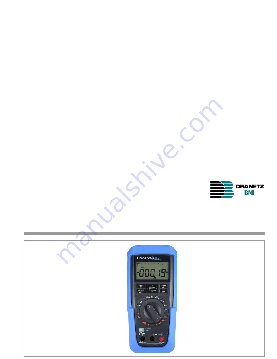
DranTech X

TRA

TRMS Digital Multimeter

User’s Guide

P/N M240H

©

2007 Rev. A

Summary of Contents for DranTech Xtra

Page 1: ...DranTech XTRA TRMS Digital Multimeter User s Guide P N M240H 2007 Rev A...

Page 2: ...ation Function DranTech XTRA V AC Hz TRMS Ri 9 M Filter V AC TRMS Ri 1 M Filter V AC DC TRMS Ri 9 M V DC Ri 9 M 1 MHz 5 V AC Keying ratio as Hz V AC 100 kHz Bandwidth V AC 15 Hz 20 kHz A AC Hz TRMS 10...

Page 3: ...ng upon the scope of the respective accessory data sheet and operating instructions www dranetz bmi com See also chapter 10 on page 64 Product Support Technical Queries use operation software registra...

Page 4: ...rent resistance alternating voltage alternating current value AC active power AC apparent power DC power capacitance frequency temperature Competent Partner GMC I Gossen Metrawatt GmbH is certified in...

Page 5: ...DranTech XTRA User s Guide 5 Contact Persons...

Page 6: ...Minimum and Maximum Values MIN MAX Function 22 4 5 Measurement Data Recording 23 5 Measurements 26 5 1 Voltage Measurement 26 5 1 1 Direct and Pulsating Voltage Measurement V DC and V DC AC 27 5 1 2...

Page 7: ...50 7 1 Activating the Interface 50 7 2 Configuring Interface Parameters 51 8 Technical Data 52 9 Maintenance and Calibration 60 9 1 Displays Error Messages 60 9 2 Batteries 60 9 3 Fuse 61 9 4 Housing...

Page 8: ...impermissible functions after the measurement cables have already been plugged in Measuring Categories and their Significance per IEC 61010 1 The measuring category and the maximum rated voltage which...

Page 9: ...ent may be damaged The instrument may not be operated if the fuse cover or the battery compartment lid has been removed or if its housing is open The input for the current measuring range is equipped...

Page 10: ...e exceeded See technical data on page 52 for overload values and overload limits Measurements may only be performed under the specified ambient conditions See page 58 regarding operating temperature r...

Page 11: ...DranTech XTRA User s Guide 11 Safety Precautions...

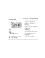
Page 12: ...Connector socket for current measurement with automatic blocking 10 Connector socket for voltage resistance temperature diode and capacitance measurement with automatic blocking 11 DATA MIN MAX key fo...

Page 13: ...appears indicates overranging 12 Diode measurement selected 13 Selected type of current 14 TRMS measurement 15 Pt100 0 selected platinum resistance thermometer with auto matic recognition of Pt100 Pt1...

Page 14: ...1 M V 0 2 V DC Direct voltage V 1 V DC AC TRMS Pulsating voltage TRMS MHz 0 2 MHz High frequency 5 V 1 Keying ratio 5 V Direct current resistance 0 2 Continuity testing with acoustic signal 1 V DC Dio...

Page 15: ...and their Significance per IEC 61010 1 on page 8 Continuous doubled or reinforced insulation Indicates EC conformity IR Position of the infrared interface window on the top of the instrument Position...

Page 16: ...13 The instrument is ready for use as soon as the key is released Display Illumination After the instrument has been switched on background illumination can be activated by briefly pressing the ON OFF...

Page 17: ...elapsed see APoFF parameter on page 47 Shutdown is acknowledged with a brief acoustic signal Exceptions include Transmission and memory mode operation continuous operation and whenever a dangerous vo...

Page 18: ...tage measuring range re mains active The Auto Ranging Function The multimeter is switched automatically to the next higher range at 11999d 1 d 01200d and to the next lower range at 01100d 1 d 10990d E...

Page 19: ...asuring range selection Zero Balancing Plug the measurement cables into the instrument and connect the free ends to each other except for capacitance measurement in which case the ends of the cables a...

Page 20: ...s is exceeded 0L overload appears at the display Exceptions 0L appears as of 1200 digits for capacitance measurement and as of 5100 digits for diode testing 4 3 2 Analog Display Measured Value Polarit...

Page 21: ...rrent measured value continues to appear However when the digital display is frozen the decimal point is fixed as well fixed measuring range symbol MAN The selected measuring range should not be manua...

Page 22: ...measuring functions The Min Max function has no effect on the analog display at which the momentary measured value continues to appear Apply the measured quantity to the instrument and set the measur...

Page 23: ...rate for memory mode operation see rAtE parameter in chapter 6 4 and then start memory mode operation First select the desired measuring function and an appropriate measuring range Check the battery c...

Page 24: ...splay after pressing MEASURE SETUP StoP StArt Acknowledge the StoP display by pressing FUNC ENTER STORE is cleared from the display indicating that recording has been ended Press MEASURE SETUP in orde...

Page 25: ...DranTech XTRA User s Guide 25 Control Functions...

Page 26: ...measurements may be made with this instrument in electrical circuits with corona discharge high voltage Special care is required when measurements are made in HF elec trical circuits Dangerous pulsat...

Page 27: ...r is connected for voltage measurement If the fuse s blowing limits are exceeded as a result of operator error both the operator and the instrument are in danger With the rotary switch in the V positi...

Page 28: ...key repeatedly until unit of measure V or V Fil appears at the display Frequency Measurement Apply the measured quantity is the same way as for voltage meas urement Manually select the measuring range...

Page 29: ...s filter is used At voltages of greater than 55 V AC or 70 V DC a danger symbol ap pears at the display COM V Temp Max 1000 V 10 kHz V 100 mV 1000 V Hz 1 Hz 100 kHz Max 100 V 10 kHz Pmax 3 x 10⁶ V x H...

Page 30: ...ng range for the voltage amplitude When the instrument is switched to frequency measurement the previously selected voltage measuring range remains active You can switch back and forth between frequen...

Page 31: ...pass filter is used At voltages of greater than 55 V AC or 70 V DC a danger symbol ap pears at the display COM V Temp Max 1000 V 10 kHz V 100 mV 1000 V Hz 1 Hz 100 kHz Max 100 V 10 kHz Pmax 3 x 10⁶ V...

Page 32: ...t transient overvoltages of up to 6 kV with wave front durations of 10 and halftimes of 1000 s Continuous load capacity is 1200 VRMS Additional influence error caused by the KS30 measuring adapter amo...

Page 33: ...d dis played using MHz as a unit of measure Pulse frequency demonstrates the reciprocal value of pulse period Keying Ratio Measurement tE tP The ratio of pulse duration to pulse period is measured wit...

Page 34: ...ment results Refer to chapter 5 1 1 regard ing testing for the absence of voltage with the help of the direct voltage measurement Set the rotary switch to Connect the device under test as shown Note U...

Page 35: ...onnect the conductor path under test as shown Depending upon the selected limit value the multimeter generates a continuous acoustic signal in the case of continuity or short circuit i e at a value of...

Page 36: ...switch to Press the FUNC ENTER key Connect the device under test as shown Conducting Direction and Short Circuit The instrument displays forward voltage in volts display 4 places As long as voltage d...

Page 37: ...accordingly displayed Press the FUNC ENTER key in order to change to the other measuring function if required The reference temperature is measured at the internal reference junction see parameter 1tE...

Page 38: ...UNC ENTER key au tomatic compensation of cable resistance is activated for all subse quent measurements The short circuit can now be eliminated and the device is ready for use Entering Cable Resistanc...

Page 39: ...ment is performed In terference voltages distort measurement results Refer to chapter 5 1 1 regarding testing for the absence of voltage with the help of the direct voltage measurement Set the rotary...

Page 40: ...DC Use specified fuses only The fuse must have a breaking capacity of at least 30 kA If the fuse for the active current measuring range blows FUSE appears at the digital display and an acoustic signa...

Page 41: ...ted at the LCD by means of the DC or the DC AC TRMS symbol Safely connect the measuring instrument without contact resist ance in series to the power consumer 2 as shown Switch power supply to the mea...

Page 42: ...ly connect the measuring instrument without contact resist ance in series to the power consumer as shown Switch power supply to the measuring circuit back on 3 Read the display Make a note of the meas...

Page 43: ...DranTech XTRA User s Guide 43 V Hz Temperature and A Hz Measurements...

Page 44: ...a parameter acknowledge it with the FUNC ENTER key The Y Z keys can be used to position the cursor at the entry posi tion The desired value is selected with the help of the UV keys Changes can only be...

Page 45: ...ce Parameters A diSP 47 A diSP analog display select display mode APoFF 47 APoFF specified time for automatic shutdown and continuous ON bAtt 46 bAtt query battery voltage bEEP 47 bEEP set the limit v...

Page 46: ...he time interval after which the respec tive measured value is transmitted to the interface or to measured value memory Any one of the following sampling rates can be selected 00 00 1 00 00 2 00 00 5...

Page 47: ...g is selected the multimeter is set to continuous opera tion and ON appears in the display to the right of the battery symbol In this case the multimeter can only be switched off manually The on setti...

Page 48: ...must be reentered after replacing the batteries 6 5 Default Settings Previously entered changes can be undone and the default settings can be reactivated This may be advisable under the following circ...

Page 49: ...DranTech XTRA User s Guide 49 Device and Measuring Parameters...

Page 50: ...set to iron see chapter 7 2 or the instrument is already switched on the first command wakes up the multimeter but does not yet execute any fur ther commands The continuous transmission operating mod...

Page 51: ...multimeter is switched off iroFF IR does not appear at the display and the infrared interface is switched off signals cannot be received 1nFo Z Z SEt rAtE V V irStb iron iroFFUV irstb iroFF default s...

Page 52: ...d 100 V 10mV 9 M 9 M 50 pF 0 05 3 0 5 9 200 d 1 30 300 d 1000 V 100mV 9 M 9 M 50 pF 0 09 3 0 5 9 200 d 1 30 300 d Voltage drop approx at upper range limit 4 4 A 100 A 10 nA 12 mV 12 mV 0 5 5 1 5 10 20...

Page 53: ...under Reference Conditions Overload Capacity 2 11 999 1199 Value Time Discharge resistance U0 max rdg d F 10 nF 10 pF 10 M 0 7 V 1 6 6 with ZERO function active 1000 V DC AC RMS Sine Max 10 s 100 nF 1...

Page 54: ...1 Influence Error rdg d 10 K Temperature 0 C 21 C and 25 C 40 C V 0 2 10 V 0 4 10 100 1 M 0 5 10 1 M 1 10 mA A 0 5 10 mA A 0 8 10 10 nF 100 F 1 5 Hz 0 2 10 C F Pt100 Pt1000 0 5 10 C F thermocouple K 0...

Page 55: ...75 3 days instrument off V A Hz C 1 x intrinsic error Influencing Quantity Sphere of Influence Measured Quantity Measuring Range Damping Common Mode Interference Voltage Interference quantity max 1000...

Page 56: ...ly Battery 2 ea 1 5 V mignon cell 2 ea size AA alkaline manganese per IEC LR6 2 ea 1 2 V NiMH rechargeable battery also possible Service life With alkaline manganese approx 200 hours Battery test Batt...

Page 57: ...ar Height 7 segment characters 15 mm Number of places 4 place 11 999 steps Overflow display 0L is displayed for 12 000 digits Polarity display minus sign is displayed if plus pole is connected to Meas...

Page 58: ...ies Relative humidity Max 75 no condensation allowed Elevation to 2000 m Deployment Indoors outdoors only within specified ambient conditions Mechanical Design Housing Impact resistant plastic ABS Dim...

Page 59: ...DranTech XTRA User s Guide 59 Technical Data...

Page 60: ...replacing the batteries The selected operating parameters remain in mem ory although date and time must be reentered Battery The current battery charge level can be queried in the 1nfo menu 1nFo bAtt...

Page 61: ...ched on with the rotary switch in the A position When the instrument is already on and the rotary switch is turned to the A position In the active current measuring range when voltage is applied If th...

Page 62: ...appears at the dis play 9 4 Housing Maintenance No special maintenance is required for the housing Keep outside sur faces clean Use a slightly dampened cloth for cleaning Avoid the use of cleansers a...

Page 63: ...instruments are guaranteed for a period of 3 years after date of shipment The manufacturer s guarantee covers materials and workmanship Damages resulting from use for any other than the intended purpo...

Page 64: ...operating instructions www dran etz bmi com 10 2 Technical Data for Measurement Cables included KS17 2 safety cable set Electrical Safety Maximum rated voltage Measuring category 1000 V CAT III 600 V...

Page 65: ...Software DranWin 10 PC software is a multilingual measurement data logging program for recording visualizing evaluating and documenting meas ured values The following conditions must be fulfilled in o...

Page 66: ...s Accessories 65 States 13 irStb 51 itEMP 46 K Keying Ratio Measurement 33 M Manufacturer s Guarantee 63 Measured Value Storage DATA Function 21 Min Max Values 22 Measurement Cables 64 Measuring Categ...

Page 67: ...isplay 13 Instrument 15 Rotary Switch Positions 14 T Temperature Measurement With Resistance Thermometers 38 With Thermocouples 37 tiME 46 48 Training 3 U Use for Intended Purpose 10 V vErSion 46 Volt...

Page 68: ...ut notice A pdf version is available on the internet Dranetz BMI 1000 New Durham Road Edison New Jersey 08818 4019 USA Phone 1 800 372 6832 or 732 287 3680 Fax 732 248 1834 www dranetz bmi com ba_gb_r...

Reviews: