background image


OPERATING AND 

INSTALLATION MANUAL 

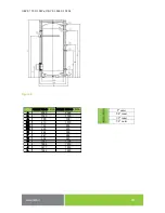
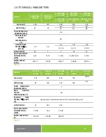
STATIONARY ELECTRICAL WATER HEATERS 


OKCE 100 S/2,2 kW 
OKCE 125 S/2,2 kW 

OKCE 160 S/2,2 kW 

OKCE 160 S/3-6 kW 

OKCE 200 S/2,2 kW 

OKCE 200 S/3-6 kW 

OKCE 250 S/2,2 kW 

OKCE 250 S/3-6 kW


OKCE 300 S/1 MPa 
OKCE 400 S/1 MPa 
OKCE 500 S/1 MPa 
OKCE 750 S/1 MPa 
OKCE 1000 S/1 MPa 


Družstevní závody Dražice 

strojírna s.r.o.


Dražice 69, 294 71 Benátky nad Jizerou


Phone.:


+420 /326 370


990


Fax:


+420 / 326 370


980


e

-

mail:


prodej@dzd.cz


Summary of Contents for OKCE 160 S/3-6 kW

Page 1: ... kW OKCE 160 S 3 6 kW OKCE 200 S 2 2 kW OKCE 200 S 3 6 kW OKCE 250 S 2 2 kW OKCE 250 S 3 6 kW OKCE 300 S 1 MPa OKCE 400 S 1 MPa OKCE 500 S 1 MPa OKCE 750 S 1 MPa OKCE 1000 S 1 MPa Družstevní závody Dražice strojírna s r o Dražice 69 294 71 Benátky nad Jizerou Phone 420 326 370 990 Fax 420 326 370 980 e mail prodej dzd cz ...

Page 2: ... OKCE 300 S 1 MPa OKCE 400 S 1 MPa OKCE 500 S 1 MPa 13 2 2 3 ELECTRIC INSTALLATION ONLY FOR OKCE 300 S 1MPa OKCE 400 S 1MPa OKCE 500 S 1MPa OKCE 750 S 1MPa OKCE 1000 S 1MPa 17 2 2 4 PLUMBING FIXTURE 18 2 3 FURTHER INFORMATION 19 2 4 FIRST COMMISSIONING 20 2 5 HEATER CLEANING AND ANODE ROD EXCHANGE 21 2 6 SPARE PARTS 21 3 OPERATION OF THERMOSTAT 22 3 1 SERVICING 22 3 1 1 OPERATION DEVICES OF THE OK...

Page 3: ... would like to thank you for your decision to use a product of our brand With this guide we will introduce you to the use construction maintenance and other information on electrical water heaters The manufacturer reserves the right for engineering modification of the product The product is designed for permanent contact with drinkable water It is recommended to use the product in indoor environme...

Page 4: ...5 mm polyurethane foam The heater shield consists of a steel powder paint coated sheet the connecting parts are metal coated In 100 125 litre heaters a flange is welded onto the upper bottom of the receptacle to which the lid of the flange is screwed A sealing ring is inserted between the flange lid and the flange Thermowells for placing a heating element and regulation and safety thermostat senso...

Page 5: ...YP OKCE 100 S 2 2 kW OKCE 125 S 2 2 kW A 902 1067 B 893 1058 C 144 144 D 524 524 L 535 635 1 3 DESIGN AND GENERAL HEATER DIMENSIONS OKCE 100 S 2 2 kW OKCE 125 S 2 2 kW Figure 1 3 4 outer 3 4 inner 1 2 inner ...

Page 6: ... S 2 2 kW OKCE 250 S 2 2 kW A 1047 1357 1537 B 705 705 705 C 79 79 79 D 584 584 584 E 519 859 1059 F 966 1279 1459 G 242 242 242 H 524 813 813 OKCE 160 S 2 2 kW OKCE 200 S 2 2 kW OKCE 250 S 2 2 kW Figure 2 3 4 outer 3 4 inner 6 4 inner ...

Page 7: ...00 S 3 6 kW OKCE 250 S 3 6 kW A 1047 1357 1537 B 705 705 705 C 79 79 79 D 584 584 584 E 518 859 1059 F 965 1279 1459 G 289 289 289 H 813 813 OKCE 160 S 3 6 kW OKCE 200 S 3 6 kW OKCE 250 S 3 6 kW Figure 3 3 4 outer 3 4 inner 6 4 inner ...

Page 8: ... 8 OKCE 300 S 1 MPa Figure 4 A 1578 B 724 C 79 D 650 F 756 G 304 J 897 3 4 outer 3 4 inner 6 4 inner ...

Page 9: ... 500 S 1MPa A 1920 1924 B 734 779 C 79 55 D 650 700 E 514 380 F 1194 1264 G 304 287 H 1289 1409 I 1798 1790 J 1005 1040 OKCE 400 S 1 MPa OKCE 500 S 1 MPa Figure 5 3 4 outer 3 4 inner 1 2 inner Thermowell for sensor 6 4 inner ...

Page 10: ...1MPa A 2030 2050 B 1030 1130 C 100 100 D1 910 1010 D2 750 850 D3 225 225 E 292 300 F 947 955 G 382 390 H 1147 1155 I 1893 1910 J 1477 1515 L 1642 1650 OKCE 750 S 1 MPa OKCE 1 000 S 1 MPa Figure 6 2 outer 5 4 inner 1 2 inner 5 4 outer ...

Page 11: ...2 5 LOAD PROFILE M L L XL XL DAILY ELECTRICITY CONSUMPTION kWh 6 23 12 12 11 96 19 74 19 67 19 23 MIXED WATER V40 l 133 17 156 44 235 47 309 66 418 23 Table 1 MODEL OKCE 300 S 1MPa OKCE 400 S 1MPa OKCE 500 S 1MPa OKCE 750 S 1MPa OKCE 1000 S 1MPa Capacity l 314 395 455 750 1000 WEIGHT kg 82 103 121 162 211 TANK OPERATING PRESSURE MPa 1 MAX HEATING WATER TEMPERATURE C 90 HEATING TIME FRTOM 10 to 60 ...

Page 12: ... the common decalcifying devices was installed with the appliance or that the thermostat was set to the minimum operating temperature of 55o C setting to position ECO Figure 19 For proper operation drinkable water of adequate quality shall be used To avoid potential sediments we recommend that the device was installed together with a water filter 2 2 ELECTRICAL INSTALLATION 2 2 1 ELECTRIC INSTALLA...

Page 13: ... is equipped with universal electrical heating unit with either fixed or optional power of heating elements apart from OKCE 300 S 1 MPa The heating unit consists of a flange to which one or three thermowells for ceramic heating units are welded and a thermowell for regulation sensors see Figure 9 Figure 10 Figure 11 A unit is attached by either 8 M 10 screws with a 168 mm clearance or 12 M 12 scre...

Page 14: ... thermostat may be set from 5 C to 74 We recommend that the sanitary water temperature is set to the maximum of 60 C This temperature ensures optimum operation of the heater since thermal losses are reduced and electricity saved After reaching the temperature set the thermostat switches off the electric circuit and thus discontinues water heating The control light signals if the element is in oper...

Page 15: ...igure 1 OKCE 160 S 3 6 kW OKCE 200 S 3 6 kW OKCE 250 S 3 6 kW OKCE 300 S 1 MPa TPK 210 12 3 6 kW OKCE 300 S 1 MPa OKCE 400 S 1 MPa OKCE 500 S 1 MPa TPK 210 12 5 9 kW TPK 210 12 8 12 kW Fastening 12 x M12 Figure 12 Wiring scheme Notice Factory connection must not be changed Cover of wiring with control Heating unit 2 2 kW Thermostat Heater run indicator lamp Figure 2 Figure 14 ...

Page 16: ...erconnect the clips on the 1 10 terminal board in accordance with the following schemes 3 kW 1 PE N AC 230 V 50 Hz 3 kW 2 PE N AC 400 V 50 Hz 4 kW 3 PE N AC 400 V 50 Hz 6 kW 3 PE N AC 400 V 50 Hz OKCE 300 S 1 MPa OKCE 400 S 1 MPa OKCE 500 S 1 MPa TPK 210 12 5 9 kW TPK 210 12 8 12 kW TPK 5 9 kW R 1 kW TPK 8 12 kW R 1 33 kW TPK 5 9 kW 5 kW 3 PE N AC 400 V 50 Hz 7 kW 3 PE N AC 400 V 50 Hz 9 kW 3 PE N...

Page 17: ...77 8 SE 378 9 5 SE 377 11 SE 378 14 SE 377 16 SE 378 19 Capacity Flange size Time of heating from 10 C to 60 C hours L Mm 8 6 5 4 3 2 5 2 1 5 300 Flange 210 RDU 18 2 5 RDU 18 3 RDU 18 3 8 RDU 18 5 RDU 18 6 RDW 18 7 5 RDW 18 10 400 Flange 210 RDU 18 3 RDU 18 3 8 RDU 18 5 RDU 18 6 RDW 18 7 5 RDW 18 10 RSW 18 12 RSW 18 15 500 Flange 210 RDU 18 3 8 RDU 18 5 RDU 18 6 RDW 18 7 5 RDW 18 10 RSW 18 12 RSW ...

Page 18: ...e spring Nominal clearance of safety valves is defined by standard 300 l heaters are supplied without the safety valve The safety valve must be easily accessible as close to the heater as possible The inlet pipes must have at least the same clearance as the safety valve Safety valve is placed high enough to secure dripping water drain by gravity We recommend mounting the safety valve onto a branch...

Page 19: ...g spontaneous heater draining and hot water penetrating back into the water main We recommend that the hot water distribution from the heater was as short as possible to minimise heat losses At least one demountable joint must be mounted between the tank and every supply pipe Adequate piping and fittings with sufficiently dimensioned maximum temperature and pressure values must be used Water heate...

Page 20: ...irst the operating and then the safety thermostat b open the hot water valve on the combination faucet c open the cold water inlet valve to the heater d when the water starts flowing through the hot water valve the filling of the heater is finished and the valve needs to be closed e if a flange lid leak is discovered the flange lid bolts need to be tightened f fasten the electric installation cove...

Page 21: ...rs deal with the cleaning and exchanging of the anode When draining water from the heater the combination faucet valve for hot water must be open preventing the occurrence of under pressure in the heater tank which would stop water from draining To prevent the occurrence of bacteria e g Legionella pneumophila within stack heating it is recommended if absolutely necessary to increase the temperatur...

Page 22: ...Figure 18 3 1 2 TEMPERATURE SETTING Water temperature is set by turning the thermostat knob The desired symbol is adjusted against the fixed point on the control panel Figure 9 Figure 19 upper limit of temp range approx 80 C Temperature C around 8 lower temperature range limit about 5 C fixed point on the control panel Ideal temperature around 55 ...

Page 23: ...ter is not warm enough Light on failure of any of the units failure of one of the heating coils in the element Water is cold Light off Thermostat failure The safety thermostat shut off the power supply Electric supply outside the heater interrupted Temperature of water is not corresponding with the temperature set on the control Light on Thermostat failure Table 11 Do not attempt to repair the fai...

Page 24: ...side from temperature resetting with a control button All electric installation handling setting and regulation feature exchange may only be implemented by a service company Both the electric and water installation must follow and meet the requirements and regulations relevant in the country of use 4 2 DISPOSAL OF PACKAGING MATERIAL AND NON FUNCTIONING PRODUCT A service fee for providing return an...

Page 25: ...re drawn together so that the insulation does not draw down and the holes in the insulation overlap the inputs and outputs on the boiler It has to be ensured that both halves of the zip closure aren t distant by more than 20 mm from one another before closing see Figure 21 On closing no foam may penetrate in the zip closure Once the insulation shell is properly fitted and the zip closure closed th...

Reviews: