background image

The original ROOTS blower still leads the way

Universal RAI

®

, URAI-DSL, 

URAI-J

-DSL, URAI-G

 and 

Metric Series

Installation, Operation & Maintenance

Contents

Information Summary ...........................................................1
Safety Precautions ................................................................3
Operating Limitations ............................................................3
Installation ........................................................................ 4-6
Technical Supplement for URAI-G blowers ...........................7
Lubrication .................................................................8, 9, 17
Operation ...........................................................................10

Troubleshooting ..................................................................11
Inspection & Maintenance ...................................................12
Figures ......................................................................... 13-16
Tables .......................................................................... 16-17
Assembly Drawings ...................................................... 18-23
Parts List ...................................................................... 24-25
Basic Connection & Drive Shaft Information .................. 26-28

o

  Check shipment for damage. If found, file claim with 

carrier and notify Roots.

o

  Unpack shipment carefully, and check contents against 

Packing List. Notify Roots if a shortage appears.

o

  Store in a clean, dry location until ready for installation. 

Lift by methods discussed under INSTALLATION to avoid 
straining or distorting the equipment. Keep covers on 
all openings. Protect against weather and corrosion if 
outdoor storage is necessary.

o

  Read OPERATING LIMITATIONS and INSTALLATION 

sections in this manual and plan the complete installation.

o

  Provide for adequate safeguards against accidents to 

persons working on or near the equipment during both 
installation and operation. See SAFETY PRECAUTIONS.

o

  Install all equipment correctly. Foundation design must be 

adequate and piping carefully done. Use recommended 
accessories for operating protection.

o


Make sure both driving and driven equipment 
is correctly lubricated before start-up. See 
LUBRICATION.

o

  Read starting check points under OPERATION. Run 

equipment briefly to check for installation errors and make 
corrections. Follow with a trial run under normal operating 
conditions. 

o

  In event of trouble during installation or operation, do 

not attempt repairs of Roots furnished equipment. Notify 
Roots, giving all nameplate information plus an outline 
of operating conditions and a description of the trouble. 
Unauthorized attempts at equipment repair may void 
Roots warranty.

o

  Units out of warranty may be repaired or adjusted by 

the owner. Good inspection and maintenance practices 
should reduce the need for repairs. 

NOTE:

 Information in this manual is correct as of the date 

of publication. Roots reserves the right to make design or 
material changes without notice, and without obligation to 
make similar changes on equipment of prior manufacture.
For your nearest Roots Office, dial our Customer Service Hot 
Line toll free; 1 877 363 ROOT(S) (7668) or direct 832-590-
2600.

Do These Things To Get The Most From Your ROOTS

 blower

ISRB-2002 rev. 0710
Summary of Contents for Universal RAI

Page 1: ...n and operation See SAFETY PRECAUTIONS o Install all equipment correctly Foundation design must be adequate and piping carefully done Use recommended accessories for operating protection o Make sure both driving and driven equipment is correctly lubricated before start up See LUBRICATION o Read starting check points under OPERATION Run equipment briefly to check for installation errors and make co...

Page 2: ...e connections or taps for instruments thermometers and pressure or vacuum gauges at or near the inlet and discharge connections of the unit These along with a tachometer will enable periodic checks of operating conditions PRESSURE The pressure rise between inlet and dis charge must not exceed the figure listed for the specific unit frame size concerned Also in any system where the unit inlet is at...

Page 3: ...ssible If lifting lugs are not available lifting slings may be passed under the cylinder adjacent to the headplates Either method prevents strain on the extended drive shaft Packaged Units When the unit is furnished mounted on a baseplate with or without a driver use of lifting slings passing under the base flanges is required Arrange these slings so that no strains are placed on the unit casing o...

Page 4: ...on in offset alignment of the shafts should not exceed 005 13 mm total indicator reading taken on the two coupling hubs Maximum deviation from parallel of the inside coupling faces should not exceed 001 03 mm when checked at six points around the coupling When a unit is BELT DRIVEN the proper selection of sheave diameters will result in the required unit speed When selecting a sheave to be fitted ...

Page 5: ...an installation with all accessory items that might be required under various operating conditions Inlet piping should be completely free of valves or other restrictions When a shut off valve can not be avoided make sure a full size vacuum relief is installed nearest the unit inlet This will protect against unit overload caused by accidental closing of the shut off valve Need for an inlet silencer...

Page 6: ...ory A simple but very effective lubrication system is employed on the drive shaft end bearings Hydraulic pressure relief fittings are provided to vent any excess grease preventing pressure build up on the seals A restriction plug and metering orifice prevent loss of lubricant from initial surges in lubricant pressure but permit venting excess lubricant under steadily rising pressures Using a press...

Page 7: ...ould be changed after initial 100 hours of operation Proper service intervals of the oil thereafter are based on the discharge air temperature of the blower Please refer to the information below to How to properly determine the oil service intervals shown on this page Unless operating conditions are quite severe a weekly check of the oil level and necessary addition of lubricant should be sufficie...

Page 8: ...wer Lithium based grease is not approved for any ROOTS blowers The lubricants selected must be compatible with the gas ROOTS Synthetic Oil Grease is superior in performance to other synthetic lubrications It has high oxidation stability excellent corrosion protection extremely high film strength and low coefficient of friction ROOTS Synthetic oil is superior in performance to petroleum based produ...

Page 9: ...anometer be connected into the discharge line if not already provided and that thermometers be in both inlet and discharge lines Readings from these instruments will show whether pressure or temperature ratings of the blower are being exceeded During the final run check operating conditions frequently and observe the oil levels at reasonable intervals If excessive noise or local heating develops s...

Page 10: ...heck carefully Re align if questionable Re adjust for correct tension Vibration 17 18 19 20 21 22 23 Misalignment Impellers rubbing Worn bearings gears Unbalanced or rubbing impeller Driver or blower loose Piping resonances Scale sludge build ups See item 15 See item 10 Check gear backlash and conditions of bearings and replace as indicated Scale or process material may build up on casing and impe...

Page 11: ... expendable items to be replaced whenever drainage from the headplate vent cavity becomes excessive or when the blower is disassembled for any reason Some oil seal leakage may occur since an oil film under the lip is required for proper operation Periodically leaked oil should be wiped off from surfaces Minor seal leak age should not be considered as indicating seal replacement Timing gear wear wh...

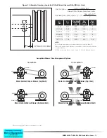
Page 12: ...RAI URAI J Units Acceptable Blower Drive Arrangement Options Belt Pull in lbs 252100 Motor BHP Blower RPM Sheave Diameter in inches Shaft load lb in Belt Pull lbs A Sheave Width 2 NOTE Arc of sheave belt contact on the smaller sheave not to be less than 170 Driver to be installed on the inlet side for vertical units and on the drive shaft side for horizontal units ROOTS recommends the use of two o...

Page 13: ...14 Dresser Roots Figure 3a Air Blower Installation with Accessories Figure 3b Gas Blower Installation with Accessories Above are suggested locations for available accessories ...

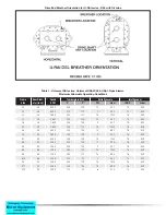
Page 14: ...tage of the WHISPAIR feature Therefore a WHISPAIR blower may be operated in the following combinations CCW Rotation Bottom Shaft Right side discharge or a Left Shaft Bottom discharge CCW Rotation Top Shaft Left side discharge or a Right Shaft Top discharge or CW Rotation Bottom Shaft Left side discharge or a Right Shaft Bottom discharge CW Rotation Top Shaft Right side discharge or a Left Shaft To...

Page 15: ...5275 210 117 7 483 15 500 32 3 5 3600 240 133 15 1034 16 539 33 3 5 3 600 225 125 12 827 15 500 36 3 5 3 600 225 125 7 483 15 500 42 4 0 3 600 240 133 15 1034 16 539 45 4 0 3600 225 125 10 690 16 539 47 4 0 3600 225 125 7 483 15 500 53 5 0 2850 225 125 15 1034 16 539 56 5 0 2850 225 125 13 896 16 539 59 5 0 2850 225 125 7 483 15 500 65 6 0 2350 250 130 15 1034 16 539 68 6 0 2350 240 133 14 965 16 ...

Page 16: ...C service temperature and moisture resistance and good mechanical stability When servicing drive end bearings of non gas blower use a NLGI 2 premium grade microgel grease with 250 F 121 C service temperature and moisture resistance and good mechanical stability Roots specifies Shell Darina SD2 NLGI 2 Product Code 5067628 NOTE Lithium based greases are not compatible with the ROOTS Synthetic Grease...

Page 17: ... SCREW IN ASSEMBLY B SEE OPERATING MANUAL IRB 180 FOR LUBRICATION INSTRUCTION C 2 1 2 3 1 2 4 REQ D SOC HD ON G E ONLY E REQ D ON 22 42 ONLY F NUT TO BE TORQUED TO 2 1 2 60 LB FT 3 1 2 110 LB FT 4 190 LB FT 5 250 LB FT G FOR SIGHT GLASS UNITS ONLY USE WASHER OUTSIDE OF GEARBOX USE RED LOCTITE ON THE THREADS NOTES SEE NOTE A DO NOT DRILL THRU SEE NOTE F SEE NOTE C SEE NOTE B SEE TABLE 11 2378 37 42...

Page 18: ...UNIVERSAL RAI URAI DSL URAI G and Metric Series 19 Assembly of UNIVERSAL RAI Blowers 6 and 7 Diameter ...

Page 19: ...HOWN IN BRACKETS ARE MILLIMETERS ORDER No No REQ D 25 13 T30099023 SECTIONAL ASSEMBLY 3 1 2 THRU 5 U RAI GAS BLOWERS A USE LOCKTITE 2 30515 BETWEEN HEADPLATE AND CYLINDER JOINTS B SEE OPERATING MANUAL IRB 180 FOR GAS BLOWERS FOR LUBRICATION INSTRUCTION C 36 45 47 REQ D SOC HD ON G E ONLY E REQ D ON 32 33 42 URAI G ONLY SEALING WASHERS BUTTONHEAD CAPSCREWS F NUT TO BE TORQUED TO 3 1 2 110 LB FT 4 1...

Page 20: ...UNIVERSAL RAI URAI DSL URAI G and Metric Series 21 Assembly of UNIVERSAL RAI Series Gas Blowers 6 Gear Diameter ...

Page 21: ...22 Dresser Roots Assembly of UNIVERSAL RAI Series DSL with Splash Lubricated Drive End 3 5 Gear Diameter ...

Page 22: ...UNIVERSAL RAI URAI DSL URAI G and Metric Series 23 Assembly of UNIVERSAL RAI Series DSL with Splash Lubricated Drive End 6 Gear Diameter ...

Page 23: ...lug Opening 1 7 Gasket Gear Box 1 11 Cylinder 1 12 Impeller Shaft Drive 1 13 Impeller Shaft Driven 1 14 Bearing Ball 3 15 Bearing Roller 1 16 Pin Dowel 4 17 Gear Nut 2 19 Key 1 21 Plug Pipe 3 23 Screw Hex Nylock 8 25 Breather Plug Vent 1 26 Screw Hex 27 Seal Lip Bearing 4 29 Washer Spring Wavy 2 31 Screw Hex Nylock 4 32 Screw Hex 10 33 Seal Lip Drive 1 34 Clamp Plate 2 35 Foot 2 37 Fitting Grease ...

Page 24: ...2 37 Fitting Grease 2 38 Fitting Relief 2 39 Washer Mounting 4 40 Screw Socket 2 42 Screw Hex 2 Item Number Part Name Quantity 1 Headplate Gear End 1 2 Headplate Drive End 1 3 Gearbox 1 4 Timing Gears 2 5 Cover Blind Plug Opening 1 7 Gasket Gear Box 1 7 Gasket DE Cover 1 11 Cylinder 1 12 Impeller Shaft Drive 1 13 Impeller Shaft Driven 1 14 Bearing Ball 3 15 Bearing Roller 1 16 Pin Dowel 4 17 Gear ...

Page 25: ...T 0 750 74 651060G0 36 2 5 NPT 0 750 102 651080G0 42 1 5 NPT 0 875 88 651090G0 45 2 5 NPT 0 875 109 651100G0 47 3 NPT 0 875 128 651120G0 53 2 5 NPT 1 125 143 651130G0 56 4 NPT 1 125 170 651140G0 59 4 NPT 1 125 204 651160G0 65 3 NPT 1 375 245 651170G0 68 5 NPT 1 375 285 651180G0 615 6 NPT 1 375 425 Basic Connection Drive Shaft Information UNIVERSAL RAI URAI Air Blowers with Grease Lubricated Drive ...

Page 26: ...rame Size Inlet Disch Connection Shaft Diameter mm Bare Weight TBD 33J 2 BSP 19 87 T304660M0 36J 2 5 BSP 19 115 TBD 45J 2 5 BSP 24 122 T304550M0 47J 3 BSP 24 141 TBD 56J 4 BSP 28 185 Universal RAI J WHISPAIR Air Blowers with Grease Lubricated Drive End Basic Connections and Drive Shaft Information Universal RAI URAI J WHISPAIR Air Blowers URAI J Metric WHISPAIR Air Blowers with Grease Lubricated D...

Page 27: ...5 BSP 24 88 651090M0 45 2 5 BSP 24 109 651100M0 47 3 BSP 24 128 651120M0 53 2 5 BSP 28 143 651130M0 56 4 BSP 28 170 651140M0 59 4 BSP 28 204 T30392060 65 3 BSP 32 245 T30394060 68 5 BSP 32 285 T30390060 615 150 NP10 32 425 T30396060 76 4 BSP 38 400 T30398060 711 150 NP10 38 530 T30340060 718 200 NP10 38 650 Universal RAI Metric URAI M Air Blowers with Grease Lubricated Drive End NOTE Metric URAI p...

Reviews: