
Contents:
Page:
Preface and General Safety Information
Part 1: Operating Instructions cl. 550-12-23; -24; -26
1.
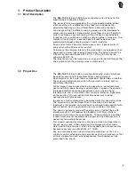
Product Description
1.1
Brief Description . . . . . . . . . . . . . . . . . . . . . . . . . . . . . . . . . . . . . . . . . . . .
5
1.2
Designated Use . . . . . . . . . . . . . . . . . . . . . . . . . . . . . . . . . . . . . . . . . . . .
5
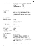
1.3
Lc Noise Level . . . . . . . . . . . . . . . . . . . . . . . . . . . . . . . . . . . . . . . . . . . . .
6
1.4
Subclasses . . . . . . . . . . . . . . . . . . . . . . . . . . . . . . . . . . . . . . . . . . . . . . .
6
1.5
Technical Data . . . . . . . . . . . . . . . . . . . . . . . . . . . . . . . . . . . . . . . . . . . . .
6
1.6
Optional Equipment . . . . . . . . . . . . . . . . . . . . . . . . . . . . . . . . . . . . . . . . . .
6
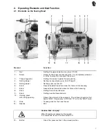
2.
Operating Elements and their Function
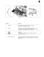
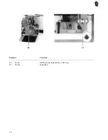
2.1
Elements on the Sewing Head . . . . . . . . . . . . . . . . . . . . . . . . . . . . . . . . . . . .
7
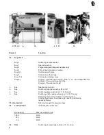
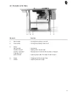
2.2
Elements on the Frame . . . . . . . . . . . . . . . . . . . . . . . . . . . . . . . . . . . . . . . .
11
3.
Operating the Controls
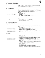
3.1
Manual Sewing . . . . . . . . . . . . . . . . . . . . . . . . . . . . . . . . . . . . . . . . . . . . .
13
3.2
Sewing with a Program . . . . . . . . . . . . . . . . . . . . . . . . . . . . . . . . . . . . . . . .
13
3.2.1 Model Selection . . . . . . . . . . . . . . . . . . . . . . . . . . . . . . . . . . . . . . . . . . . .
13
3.2.2 Sewing . . . . . . . . . . . . . . . . . . . . . . . . . . . . . . . . . . . . . . . . . . . . . . . . .
13
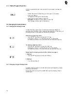
3.3
Partial Program Selection . . . . . . . . . . . . . . . . . . . . . . . . . . . . . . . . . . . . . . .
14
3.4
Changing Crimping Values . . . . . . . . . . . . . . . . . . . . . . . . . . . . . . . . . . . . . .
14
3.4.1 Changing All Crimping Values . . . . . . . . . . . . . . . . . . . . . . . . . . . . . . . . . . . .
14
3.4.2 Changing a Single Crimping Value . . . . . . . . . . . . . . . . . . . . . . . . . . . . . . . . . .
14
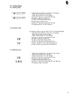
3.5
Editing Mode . . . . . . . . . . . . . . . . . . . . . . . . . . . . . . . . . . . . . . . . . . . . . .
15
3.5.1 Altering a Step . . . . . . . . . . . . . . . . . . . . . . . . . . . . . . . . . . . . . . . . . . . . .
15
3.5.2 Inserting a Step . . . . . . . . . . . . . . . . . . . . . . . . . . . . . . . . . . . . . . . . . . . .
15
3.5.3 Deleting a Step . . . . . . . . . . . . . . . . . . . . . . . . . . . . . . . . . . . . . . . . . . . . .
15
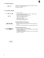
3.6
Deleting a Model . . . . . . . . . . . . . . . . . . . . . . . . . . . . . . . . . . . . . . . . . . . .
15
3.7
Generating a Program . . . . . . . . . . . . . . . . . . . . . . . . . . . . . . . . . . . . . . . . .
16
4.
Operating the Sewing machine
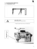
4.1
Threading the Needle Thread . . . . . . . . . . . . . . . . . . . . . . . . . . . . . . . . . . . . .
17
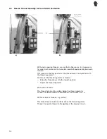
4.2
Needle Thread Quantity for Sure Stitch Formation . . . . . . . . . . . . . . . . . . . . . . . . .
18
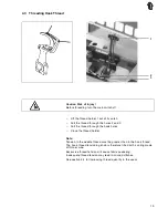
4.3
Threading the Hook Thread . . . . . . . . . . . . . . . . . . . . . . . . . . . . . . . . . . . . . .
19
4.4
Setting the Hook Thread Take-up Lever . . . . . . . . . . . . . . . . . . . . . . . . . . . . . . .
20
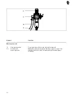
4.5
Setting the Pressure Foot Lift . . . . . . . . . . . . . . . . . . . . . . . . . . . . . . . . . . . . .
21
4.6
Switching the Edge Cutter On and Off . . . . . . . . . . . . . . . . . . . . . . . . . . . . . . . .
22
4.7
Calling Up Crimping Values . . . . . . . . . . . . . . . . . . . . . . . . . . . . . . . . . . . . . .
23
4.8
Setting of Standard Stitch Length . . . . . . . . . . . . . . . . . . . . . . . . . . . . . . . . . .
24
4.9
Threading of Lower Tape Feed (only 550-12-16) . . . . . . . . . . . . . . . . . . . . . . . . . .
25
5.
Maintenance
. . . . . . . . . . . . . . . . . . . . . . . . . . . . . . . . . . . . . . . . . . . . . .
26