
USER MANUAL
EZY-LAN 22.07-M:1.0-H:3b/4a/4b-F:3.3.4+
EZY-LAN Wireless alarm panel with Et Wi-Fi + GSM + LTE
1
General
EZY-LAN is an alarm control unit that combines
the best of the latest technologies available with
a pleasant, compact, modern and elegant design.
It manages up to 64 external devices, which can
be divided into a maximum of 8 freely partitionable
sectors.
Up to 32 different users can control the control
unit via App or keyfob. The double radio section
of the latest generation in the 868MHz
bidirectional multi-channel band allows safe,
reliable and efficient communication.
EZY-LAN gives its best when connected to the
internet - via Ethernet cable, 2.4GHz Wi-Fi or LTE
data connection - and can be controlled in real
time from the App on any device.
Whether it is a smartphone or a tablet (Apple iOS
and Android), the management and programming
interface is presented in the same form: simple,
intuitive, immediate!
EZY-LAN integrates a video verification function -
usable both with radio photo sensors and with IP
cameras (Dahua, Sunell, Provision) - which
allows you to view within the same App animated
images relating to alarm events or captured at the
request of the user.
EZY-LAN also interfaces with Shelly Wi-Fi
modules for home automation control of lights,
shutters, gate openings, irrigation or other generic
electrical loads powered at 230Vac or 12Vdc.
2
Priority of connections
The channel used by the control panel for
connection to the internet follows a priority logic.
The Ethernet cable is the primary channel that is
used if a network cable is connected.
Wi-Fi (if enabled in programming) is the
alternative channel used when a network cable is
not connected.
The LTE connection with the SIM card (if enabled
in programming) is the channel used when the
Ethernet / Wi-Fi connection is absent or there is
no internet on one of the two connections.
3
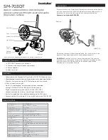
Identification of the parts
FRONTAL VIEW
1
–
led power
2
–
led Ethernet
3
–
led Wi-Fi
4
–
led GSM + LTE
5
–
programmable central button
6
–
multicolor led ring
4
Signals of the luminous ring
The luminous ring visible around the central
button (6), if enabled during the programming
phase, provides information on the status of the
system.
The luminous intensity of the ring (6) is reduced
after 60 seconds of inactivity of the control unit, to
reduce any disturbance at night. Return to
maximum brightness as soon as you perform an
operation on the control unit.
When the control unit is powered only by battery
(no external power supply), in order to reduce
consumption,
the
ring
(6)
only
flashes
periodically.
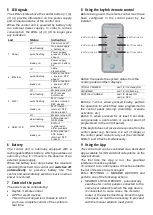
Luminous
ring signals meanings (6)
Green
Disarmed
Green / Blue
(blinking)
Disarmed with door open
Green / Red
(blinking)
Disarmed with alarm memory
Red
Totally armed
Orange
Partially armed
Exit time (flashing)
Entry time (flashing)
Violet (blinking)
Alarm in progress
White (blinking)
Panel in SETUP mode
Blue (blinking)
Panel in TEST mode
1
2
3
4
5
6