24V
I-RS 485
Intercom
4...20
mA
12,
14
12,
14
11,
13
11,
13
RS 485
external
24V
5
24V
I-RS 485
Intercom
4...20
mA
12,
14
12,
14
11,
13
11,
13
RS 485
external
24V
5
Safety Information
The installation, commissioning, operation, maintenance and dismantling of all de-
vices must only be carried out by qualifi ed specialised personnel and electrical work
only by qualifi ed electricians.
Please ensure that you have read and understood the operating manual, and store it
in a place where it can be referred to in future!
If necessary, load and unload the packages with an appropriate lifting device.
The applicable laws, standards or guidelines relating to the use or intended purpose
must be observed.
Devices must only be used in accordance with their proper and designated use. The
safety of operating personnel and the system cannot be guaranteed if the product is
used in a diff erent way from its designated use.
Before commissioning the device it must be ensured that:
electrical work has been carried out properly and in accordance with local regula-
tions!
protection from electric shock is ensured!
all cables are suffi ciently dimensioned and secured!
When working on an opened device, there is a:
Please also observe the operating manuals of the measuring devices to be connected.
Designated use
The terminal boxes are suitable for supplying DURAG measuring devices with the
required operating voltage. The type D-TB 200 also supplies the measuring devices with
the required purge air. In both types, mains and data cables for the measuring system
are connected to the available terminals in accordance with the relevant connection
diagram.
Device description
Installation
When choosing the installation location and during the installation of the terminal
box, the parameters specifi ed in the technical data must be complied with.
The intake air must be as dry as possible as well as free from dust and oil (please ob-
serve specifi cations on relative humidity).
The terminal box is installed with the cable glands facing downwards. Unused open-
ings must be sealed to prevent the penetration of moisture.
The terminal box must be freely accessible, e. g. for changing the air fi lter.
Planning instructions for electrical connections
Route cables for the mains and data cables separately.
The mains cable should use H 07 RR – U 3 G 1.5 or the equivalent. The material of the
conductors and sheath must be appropriate to the conditions at the operating site.
Secure the mains cable using a 16 A circuit breaker. Install the circuit breaker next to
the terminal box and clearly mark it as the isolation switch for the device.
The individual wires of the mains cable must be secured, e. g. using cable ties. When a
wire is released, it must not make contact with the adjacent terminals.
Connect the data cable to the terminals in the terminal box: with shielded lines,
twisted pairs of fi ne-wire fl exible cores, operational capacitance approx. 80 nF/km.
Use the appropriate twisted pairs of cores (e. g. RS 485 A and B, 4 … 20 mA + and –) for
the associated connections!
Always connect the shielding on both ends.
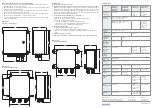
Data cable connection
Terminal box Ax2-xxxx1-Wx
Terminal box Ax2-xxxx3- Wx
X1
Supply voltage
X2
RS 485 Modbus RTU
X3
Analogue output, digital outputs
X4
For factory wiring of cable or plug connectors to the measuring head only.
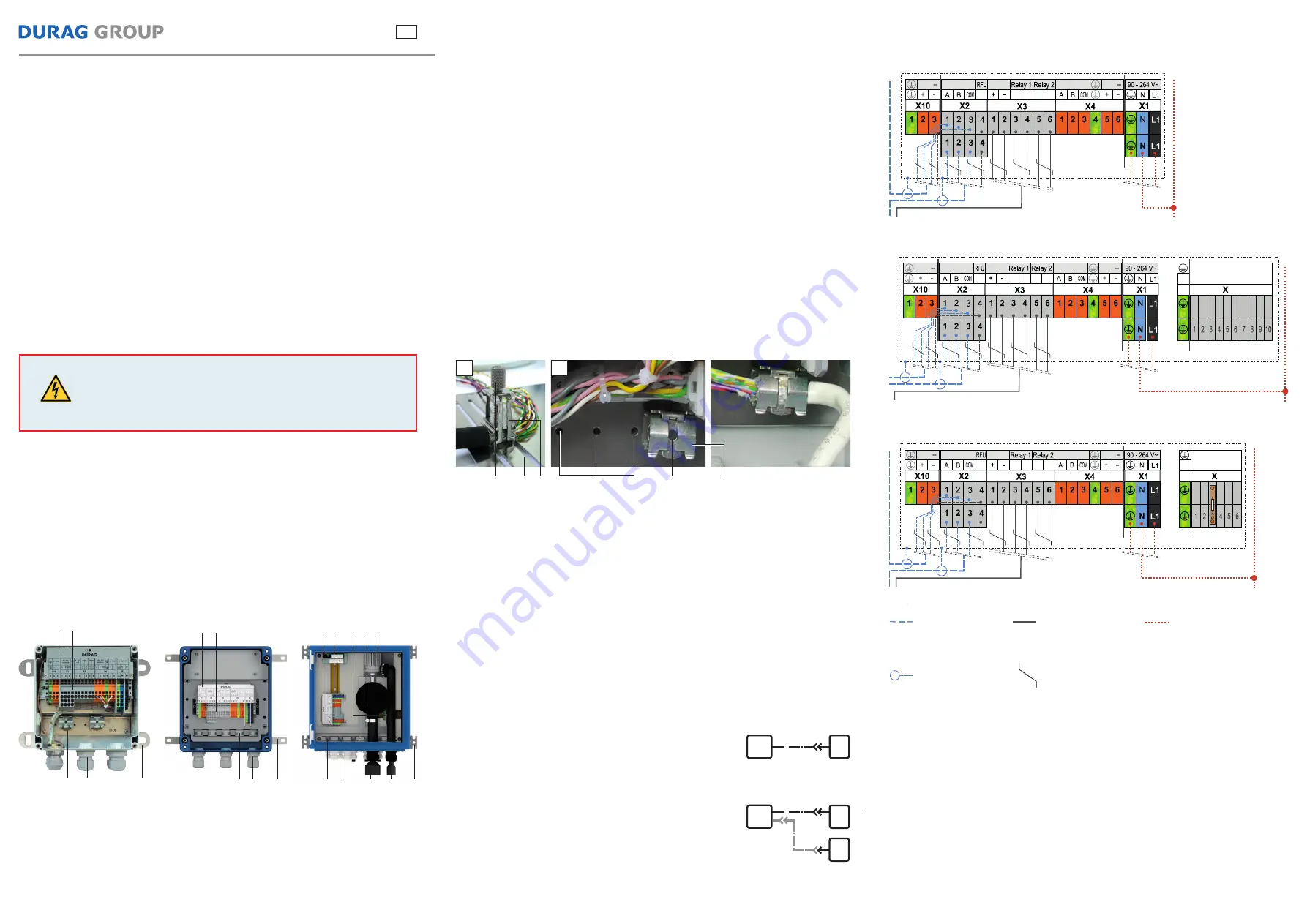
X5
For factory wiring of purge air controller to the measuring head only;
For
Terminal box Ax2-xxxx3-Wx:
Remove resistor (blower stage 2) or install resistor (blower stage 1)
as required (X5:3)
X10
like X4
Risk to life due to electric current!
Improper handing will result in serious personal injury.
Once the housing or touch guard of the terminal box have been
opened, live parts are accessible.
Disconnect mains cables!
DANGER
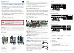
Strip back approx. 20 mm of the outer insulating layer of the data cable above the shield-
ing in addition to the exposed cores.
Guide the data cable through the cable gland
(4)
and into the terminal box.
Secure the cable and connect the shielding:
D-TB x00 Ax2-xxxxx-xx (see Fig. 1):
Put the cable in position, place the shield terminal
(3a)
over the stripped shielding on
the guide rail
(12)
and engage it. Now move it to the desired position.
Fix the cable in place using the knurled screw
(11)
. (Note: To remove the terminal, the
knurled screw is screwed completely upwards).
D-TB 100 Ax1-P5xxx-xx (see Fig. 2):
If necessary, move the shield terminal
(3b)
. To do this, loosen the hexagon socket
screw
(14)
, set the terminal on the desired tapped hole
(15)
, align it and tighten the
screw
(14)
.
Using a screwdriver or other suitable tool, press the recess
(13)
down and slide the
stripped shielding between the clamping jaws. Now remove the screwdriver.
Connect the wires in accordance with the connection diagram.
For
D-TB 100 Ax1-P5xxx-xx
, correctly align the housing cover before installation.
Figures are of diff erent scales
1
Connection diagram
2
Terminals
3
Shield terminals
4
Cable glands
5
Air suction opening
D-TB 100 Ax1-P5xxX-xx
D-TB 100 Ax2-MAxxX-xx
D-TB 200 Ax2-xxxxx-xx
Connection
DURAG Modbus
Operating Manual
Terminal Box (D-TB 100, D-TB 200)
EN
A measuring head is connected via the factory-installed ca-
ble on the terminal box
(TB – Fig. to the right)
with M23
socket.
For measuring devices with two measuring heads (e. g.
D-FL 220) a terminal box with an additional panel jack is
used. An additional connecting cable with M23 plug and
socket to the cable ends is also required for measuring head
B. Measuring head A is connected via the factory-installed
cable on the terminal box with M23 socket. For measuring
head B, the socket of the connecting cable is inserted into
the M23 plug at the measuring head, the cable plug is then
inserted into the additional panel jack of the terminal box
(TB – Fig. to the right)
.
TB
A
A
B
TB
Relay and power
connections
(if required)
Supply voltage
2-stage
purge air
controller
output-controlled
purge air controller
24V
I-RS 485
Intercom
4...20
mA
12,
14
12,
14
11,
13
11,
13
RS 485
external
24V
Shielded cable
Twisted cores
Terminal box Ax2-xxxxX-Wx and Ax1-xxxxX-Wx
Once the supply voltage has been switched on, the terminal box is ready for operation.
1 2
3 4
7
1 2
3
5
6
7
8 9 10
4
1 2
7
4
3
11
15
3a
13
14
3b
1
2
12
6
Hose connection for purge air tube to
measuring device
7
Attachment clips
8
Purge air controller terminals
9
Filter housing
10
Fan


