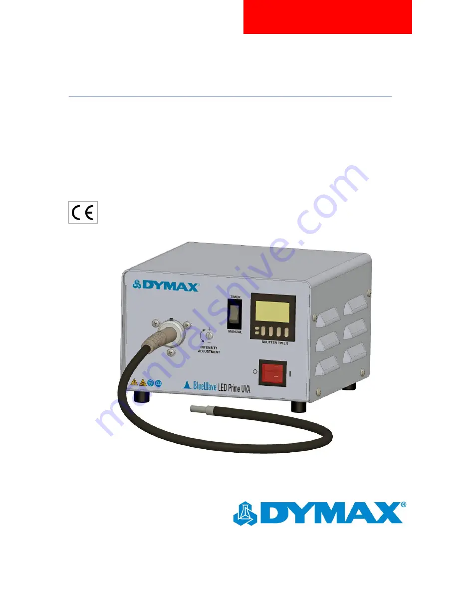
dymax BlueWave LED Prime UVA DX-1000, User Manual
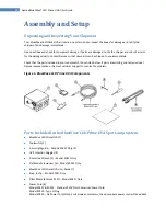
The dymax BlueWave LED Prime UVA DX-1000 is an advanced curing solution designed for various applications. Ensure optimal usage with our comprehensive User Manual, available for free download on our website. Discover step-by-step instructions and valuable insights to maximize the potential of your DX-1000 device.
Share
Download

Reviews:
No comments
Related manuals for BlueWave LED Prime UVA DX-1000

ES9465
Brand: Oki Pages: 4

eBOX671-521-FL Series
Brand: AXIOMTEK Pages: 2

ACST-1500B Series
Brand: Larscom Pages: 340

Nuvo-2400 Series
Brand: Neousys Technology Pages: 81

ducktrack DR1
Brand: Armorgard Pages: 8

Bolsa 3D Flexel
Brand: Sartorius Stedim Biotech Pages: 33

iNetVu MP- 80
Brand: C-COM Satellite Systems Pages: 68

VRM 24F391
Brand: Graco Pages: 87

IS-033
Brand: Baader Pages: 46

VPC-061A
Brand: Ulvac Pages: 29

VPC-1100
Brand: Ulvac Pages: 39

LONG REACH CCHA
Brand: Allied Systems Pages: 19

960-3
Brand: Kval Pages: 68

700-DC
Brand: Kval Pages: 72

ECX-1400 Series
Brand: Vecow Pages: 146

OPC8008
Brand: ADS-tec Pages: 61

GateKeeper
Brand: entegris Pages: 8

R23ATR Series
Brand: ELTEX Pages: 28


