background image

SAFETY INSTRUCTIONS

Carefully Read all instructions before operating or servicing any Dynabrade

®

Abrasive Power Tool.

Products offered by Dynabrade are not to be modified, converted or otherwise altered from the original design without expressed written
consent from Dynabrade, Inc.

Tool Intent:  

Right-Angle Buffer/Polishers are ideal for removal and polishing of materials using deburring, cleaning and polishing accessories.

Do Not Use Tool For Anything Other Than Its Intended Applications.

Training:  

Proper care, maintenance, and storage of your tool will maximize their performance.

• Employer's Responsibility  – Provide right-angle buffer/polisher operators with safety instructions and training for safe use of tools and accessories.

Accessory Selection:

• Abrasive/accessory RPM (speed) rating MUST be approved for AT LEAST the tool RPM rating.

• Before mounting an accessory, visually inspect for defects.  Do not use defective accessories.

• Use only recommended accessories.  See back page of manual and Dynabrade catalog.

• Follow tool specifications before choosing size and type of accessory.

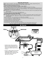
• Only use recommended fittings and air line sizes.  Air supply hoses and air hose assemblies must have a minimum working pressure rating of 150 PSIG

(10 Bars, g) or 150 percent of the maximum pressure produced in the system, whichever is higher.  (See tool Machine Specifications table.)

Parts Page Reorder No. PD03•27

Effective July, 2003

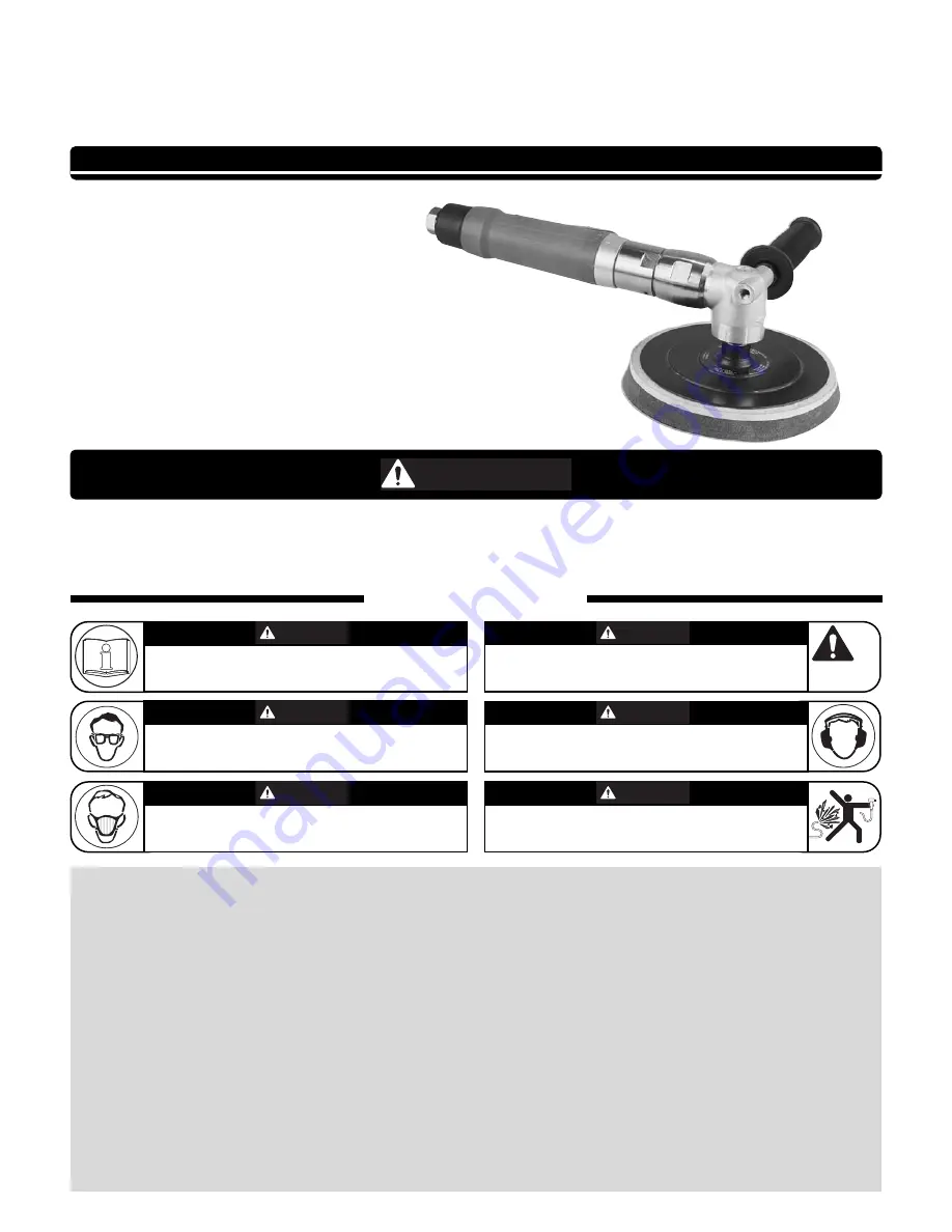
1hp Right-Angle Buffer/Polisher

Governor Controlled

Air Tool Manual – Safety, Operation and Maintenance

Models:

51390 – 1,250 RPM, 5/8"-11
51391 – 1,800 RPM, 5/8"-11
51392 – 2,800 RPM, 5/8"-11
51393 – 4,500 RPM, 5/8"-11
51394 – 1,250 RPM, M14 x 2
51395 – 1,800 RPM, M14 x 2
51396 – 2,800 RPM, M14 x 2
51397 – 4,500 RPM, M14 x 2

SAFETY LEGEND

WARNING

WARNING

Read and understand tool manual before

work starts to reduce risk of injury to

operator, visitors, and tool.

WARNING

Eye protection must be worn at all times,

eye protection to conform to ANSI Z87.1.

WARNING

Respiratory protection to be used when exposed to

contaminants that exceed the applicable threshold

limit values required by law.

WARNING

Practice safety requirements.  Work alert,

have proper attire, and do not operate tools under

the influence of alcohol or drugs.

WARNING

Ear protection to be worn when exposure to sound,

exceeds the limits of applicable Federal, State or

local statues, ordinances and/or regulations.

WARNING

Air line hazard, pressurized supply lines and flexible

hoses can cause serious injury.  Do not use dam-

aged, frayed or deteriorated air hoses and fittings.

Read and understand this tool manual before operating your air tool.  Follow all safety rules for the protection of operating person-
nel as well as adjacent areas.  Always operate, inspect and maintain this tool in accordance with the American National Safety
Institute (ANSI) Safety Code for Portable Air Tools – B186.1.  For additional safety information, refer to Safety Requirements for the
Use, Care and Protection of Abrasive Wheels – ANSI B7.1, Code of Federal Regulation – CFR 29 Part 1910, European Committee for
Standards (EN) Hand Held Non-Electric Power Tools – Safety Requirements and applicable State and Local Regulations.

SAVE THIS DOCUMENT, EDUCATE ALL PERSONNEL

Summary of Contents for 51390

Page 1: ...ation and Maintenance Models 51390 1 250 RPM 5 8 11 51391 1 800 RPM 5 8 11 51392 2 800 RPM 5 8 11 51393 4 500 RPM 5 8 11 51394 1 250 RPM M14 x 2 51395 1 800 RPM M14 x 2 51396 2 800 RPM M14 x 2 51397 4 500 RPM M14 x 2 SAFETY LEGEND WARNING WARNING Read and understand tool manual before work starts to reduce risk of injury to operator visitors and tool WARNING Eye protection must be worn at all time...

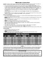
Page 2: ...ssory Connect air tool to power source Be careful NOT to depress throttle lever in the process Do not expose air tool to inlet pressure above 90 PSIG or 6 2 Bars Caution After installing the accessory before testing or use and or after reassembling tool the right angle buffer polisher must be started at a reduced speed to check for good balance Gradually increase tool speed DO NOT USE if tool vibr...

Page 3: ... few drops of Dynabrade Air Lube P N 95842 to the air line and start the tool a few times to lubricate air motor Check for excessive tool vibration Handling and Storage Use of tool rests hangers and or balancers is recommended Protect tool inlet from debris see Notice below DO NOT carry tool by air hose or near the tool throttle lever Protect abrasive accessories from exposure to water solvents hi...

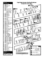
Page 4: ...0 RPM Models 41 All Housings Include Warning Specification Labels 20080 Housing Model 51390 20081 Housing Model 51391 20082 Housing Model 51392 20083 Housing Model 51393 20084 Housing Model 51394 20085 Housing Model 51395 20086 Housing Model 51396 20087 Housing Model 51397 42 96444 Pin 43 51949 Safety Lever Assembly 44 51946 Valve Stem Assembly Incl 96443 O Ring 45 51945 Valve Seat 46 51944 Tip Va...

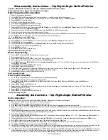
Page 5: ...et bushing with muffler assembly twist counterclockwise 3 Remove 53682 Gasket 51943 Spring 96442 O Ring 51940 Spacer 94528 Felt Silencer 53686 Muffler Cap 94924 Wave Spring and 53683 Spacer from 53681 Inlet Bushing 4 Remove 51944 Tip Valve and 51945 Valve Seat 5 Remove housing and 51989 Repair Collar and lay collar on bench with flange facing down so it is supporting throttle lever Place a 3 32 3 ...

Page 6: ... Align 51936 Coupling Insert into 51935 Coupling in right angle head assembly and thread motor into 53650 Lock Ring twist clockwise 25 Secure 53600 Right Angle Housing against both side handle bosses in a padded vise 26 Rotate motor housing and 53650 Lock Ring until throttle lever is located between the 9 11 o clock position Throttle lever in this position safe guards against accidental start ups ...

Page 7: ...rew 1 L 22 01041 Grease Fitting 1 X 23 53695 Adapter 1 X 24 See Pg 4 Carrier 1 X 25 See Pg 4 Gear 2 X 26 04026 Needle Bearing 4 X 27 53679 Shaft 1 X 28 53665 Ring Gear 1 X 29 51951 Shim Pack 1 T L 30 51922 Front Bearing Plate 1 X 31 96441 Pin 2 X 32 51927 Spacer 1 T X 33 See Pg 4 Rotor 1 X 34 51926 Blade 4 pkg 1 T X 35 51925 Cylinder 1 X 36 51923 Rear Bearing Plate 1 X 37 02057 Bearing 1 T X 38 96...

Page 8: ...gal 3 8 L Reference Contact Information 1 American National Safety Institute ANSI 3 European Committee for Standardization 25 West 43rd Street Rue de Stassart 36 Forth Floor B 1050 Brussels Belgium New York NY 10036 Tel 1 212 642 4900 Fax 1 212 398 0023 2 Government Printing Office GPO Superintendent of Documents Attn New Orders P O Box 371954 Pittsburgh PA 15250 7954 Tel 1 202 512 1803 95263 17 m...

Reviews: