background image

Operating Instruction

Original Operating Instructions

DR7X
Vibratory tamper

S/N 101 924 05 1001> / S/N 101 924 06 1001>


DL8 203 46 EN

© 04/2018

Summary of Contents for DR7X

Page 1: ...Operating Instruction Original Operating Instructions DR7X Vibratory tamper S N 101 924 05 1001 S N 101 924 06 1001 DL8 203 46 EN 04 2018...

Page 2: ...2...

Page 3: ...to the machine 22 3 3 4 Damage defects misuse of safety devices 22 3 4 Handling fuels and lubricants 23 3 4 1 Preliminary remarks 23 3 4 2 Safety regulations and environmental protection regulations f...

Page 4: ...1 Preliminary remarks and safety notes 64 8 2 Fuels and lubricants 65 8 2 1 Engine oil 65 8 2 2 Fuel 65 8 2 3 Gear oil SAE 75W 90 66 8 3 List of fuels and lubricants 67 8 4 Running in instructions 68...

Page 5: ...up refitting 99 9 1 Changing the tamper foot plate 100 10 Troubleshooting 101 10 1 Preliminary remarks 102 10 2 Engine faults 103 10 3 What to do if the engine has flooded 105 11 Disposal 109 11 1 Fi...

Page 6: ...Table of contents DR7X 6...

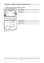
Page 7: ...1 Introduction Introduction DR7X 7...

Page 8: ...g maintenance and repair measures to maintain the functional safety of your machine A description of all necessary maintenance work maintenance intervals as well as information on fuels and lubricants...

Page 9: ...t constitute an extension of the warranty and liability conditions specified in the general sales and delivery conditions of Dynapac GmbH We wish you successful work with your Dynapac machine Introduc...

Page 10: ...ngine type 1 Engine number 2 Made by Designation Type Nominal Power Operating Mass Year of Construction Serial No Made in Germany Ammerl nder Str 93 D 26203 Wardenburg 1 2 B 924 0001 Fig 1 Machine typ...

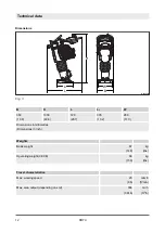
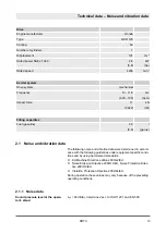
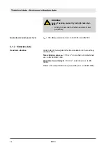
Page 11: ...2 Technical data Technical data DR7X 11...

Page 12: ...2 280 11 0 Dimensions in millimetres Dimensions in inch Weights Basic weight 67 148 kg lbs Operating weight CECE 68 150 kg lbs Travel characteristics Max working speed 20 66 m min ft min Max area outp...

Page 13: ...nd vibration data were determined in accord ance with the following guidelines under equipment specific condi tions and by using harmonized standards n EU Machine Directive edition 2006 42 EU n Noise...

Page 14: ...ctor total of the weighted effective acceleration in three orthog onal directions Total vibration value ahv 5 5 m s2 on crushed rock determined acc to EN 500 ISO 5349 Associated uncertainty K 0 8 m s2...

Page 15: ...3 Concerning your safety Concerning your safety DR7X 15...

Page 16: ...s n generally accepted safety and road traffic regulations n country state specific safety regulations It is the duty of the operator to be acquainted with the safety regu lations and to apply these a...

Page 17: ...actices for safe and environment friendly disposal of fuels and lubricants as well as replacement parts 3 1 3 Personal protective equipment Depending on the work to be carried out personal protective...

Page 18: ...use This machine must only be used for n Compaction of all types of soils n Repair work on all types of soil n Paving of walkways n Work in trenches n Underfilling and compaction of hard shoulders Int...

Page 19: ...n n Ramming of poles n Vibrating of paving blocks It is not permitted to stand on the machine while working starting and operation of the machine in explosive environments and in underground mining is...

Page 20: ...regular safety inspections 3 2 2 Expert qualified person An expert qualified person is a person who based on his her pro fessional education and experience has profound knowledge in the field of cons...

Page 21: ...operate the machine Persons under the influence of alcohol medication or drugs are not allowed to operate service or repair the machine Maintenance and repair work requires specific knowledge and must...

Page 22: ...t be informed about the dangers that arise from the operation of the machine 3 3 2 Regular safety inspections Have the machine inspected by an expert qualified person as required for the conditions th...

Page 23: ...name of substance n possible dangers n composition information on constituents n first aid measures n fire fighting measures n measures in case of accidental release n handling and storage n limitati...

Page 24: ...caused by contact with oil Wear your personal protective equipment pro tective gloves protective clothing Do not inhale any oil vapours Avoid contact CAUTION Danger of slipping on spilled oil Immediat...

Page 25: ...Health hazard caused by contact with gasoline Wear your personal protective outfit protective gloves protective clothing Do not inhale any fuel fumes Do not swallow gasoline Avoid contact with gasoli...

Page 26: ...with fuel sta bilizer Wear your personal protective outfit protective gloves protective clothing Do not inhale any fuel stabilizer fumes Do not swallow fuel stabilizer Avoid contact with fuel stabiliz...

Page 27: ...ine components Secure the machine on the transport vehicle against rolling slip ping and turning over Loads must only be attached and hoisted by an expert capable person Use only lifting gear and lift...

Page 28: ...func tion tests If the following tests reveal damages or other faults the machine must not be operated until these deficiencies have been corrected Do not operate the machine with defective indicators...

Page 29: ...test showed CO emissions below the occupational exposure limit OEL according to TRGS 900 when operating a maximum of 4 times 15 minutes per shift 8 hours For this reason take care to ensure sufficient...

Page 30: ...y be the steering bow Guide the machine so hat your hands do not hit against solid objects Watch out for unusual noises and development of smoke Perform trouble shooting and have the fault corrected 3...

Page 31: ...and heat sources Apply measures against electrostatic charging Do not spill any fuel Catch running out fuel do not let it seep into the ground Wipe off spilled fuel Keep dirt and water away from the f...

Page 32: ...ilter no dirt should fall into the air duct Do not work on the hot exhaust danger of burning Store used filters and other oil contaminated materials in a sepa rate specially marked container and dispo...

Page 33: ...warning sign Only operate the machine after it has been repaired When replacing safety relevant components only original spare parts must be used Repairs must only be performed by an expert qualified...

Page 34: ...1 2 6 2 3 4 1 2 1 5 Low Oil Level No Start Max 0 3 l 18 3 in 3 3 6 Sec 1 2 MINUTEN MIN MAX 3600 4200 min 1 2 MINUTEN MIN MAX MAX 3850 4200 min 1 MIN 1850 2000 min 1 1 OFF ON OFF ON Made by Designation...

Page 35: ...er Do not inhale exhaust gases Do not operate inside closed areas Warning sign Fire hazard Fill up with fuel only when engine is stopped and has cooled down Instruction sticker Wear ear defenders Fig...

Page 36: ...icker Lifting point Information sticker Lashing point Information sticker Guaranteed sound capacity level Information sticker pre tensioned spring Fig 11 Fig 12 Fig 13 Fig 14 Concerning your safety Si...

Page 37: ...ctions Machine type plate example Made by Designation Type Nominal Power Operating Mass Year of Construction Serial No Made in Germany Ammerl nder Str 93 D 26203 Wardenburg B 924 0002 Fig 16 Concernin...

Page 38: ...Concerning your safety Signage DR7X 38...

Page 39: ...4 Indicators and control elements Indicators and control elements DR7X 39...

Page 40: ...1 3 RUN B 924 0007 Fig 17 1 Engine oil level warning light 2 Engine stop switch 3 Operating hour meter engine rpm meter 4 Throttle lever 5 Recoil starter 6 Choke lever Indicators and control elements...

Page 41: ...5 Checks prior to start up Checks prior to start up DR7X 41...

Page 42: ...fixed settings WARNING Health hazard caused by fuels and lubricants Safety regulations and environmental protec tion regulations must be followed when han dling fuels and lubricants Chapter 3 4 Han dl...

Page 43: ...lines for condition and leaks 2 Check bolted connections for tight fit 3 Check machine for contamination and damage 4 Check the hydraulic oil cooler for dirt 5 Check starter rope for chafing Checks p...

Page 44: ...is in horizontal posi tion 2 Clean the area around the oil dipstick 1 3 Unscrew the dipstick and wipe it clean with a lint free clean cloth 4 Insert the dipstick into the oil filler socket do not scr...

Page 45: ...refuelling process Contaminated fuel can cause malfunction or even damage of the engine If necessary fill in fuel through a screen filter Use only fuel of the permitted specification Chapter 8 2 2 Fue...

Page 46: ...machine in secured condition Chapter 6 4 Parking the machine in secured condition on page 55 2 Allow the engine to cool down 3 Check all rubber buffers for tight fit cracks and tear offs 4 Replace da...

Page 47: ...6 Operation Operation DR7X 47...

Page 48: ...guide handle position 1 Park the machine in secured condition Chapter 6 4 Parking the machine in secured condition on page 55 2 Disassemble the fastening screws and washers on both sides 3 Set the ste...

Page 49: ...ensure adequate ventilation when working in trenches WARNING Loss of hearing caused by too high noise bur dens Wear your personal protective equipment ear protection Protective equipment n Hearing pr...

Page 50: ...se the choke Always close the choke to start a cold and warm engine 4 Pull the rope by the starter handle until resistance can be felt 5 Guide the starter handle back to initial position Fig 24 Fig 25...

Page 51: ...position 8 If the engine does not start during the first attempt repeat the starting process 9 Open the choke 3 to 6 seconds after the engine has started running 10 Set the throttle lever to position...

Page 52: ...starter is frequently operated with the choke closed the engine will draw in too much fuel and is unable to start Chapter 10 3 What to do if the engine has flooded on page 105 Operation Starting the e...

Page 53: ...ep your feet clear of the tamper foot plate Always hold on to a running machine Always keep an eye on a running machine WARNING Loss of hearing caused by too high noise bur dens Wear your personal pro...

Page 54: ...change the engine speed and or inclination of the tamper NOTICE The centrifugal clutch may be damaged Do not work with engine speeds which are below the working range 4 If the display LOW appears incr...

Page 55: ...le for about two minutes 2 Set the engine stop switch to position OFF The engine is shut down 3 Park the machine so that it cannot turn over 4 Pull the rope by the starter handle until resistance can...

Page 56: ...seconds after starting the engine Display Description Engine speed in the working range Engine speed below the working range Display LOW alternately displayed with the engine speed to increase the en...

Page 57: ...indicator or the hour meter is displayed 3 Press the function key for three seconds The maintenance indicator is reset to 100 hours The hour meter is reset to zero hours Resetting the maintenance indi...

Page 58: ...Operation Operating hour meter engine rpm meter DR7X 58...

Page 59: ...7 Loading transporting the machine Loading transporting the machine DR7X 59...

Page 60: ...ke sure the load does not move in an uncontrolled way If necessary hold the load steady with guide ropes Protective equipment n Protective gloves n Safety shoes 1 Park the machine safely Chapter 6 4 P...

Page 61: ...ot components Wear your personal protective equipment protective gloves protective clothing Avoid touching hot components Lay the machine on the rollers B 541 0017 Fig 41 Loading transporting the mach...

Page 62: ...amaged by machine parts Protective equipment n Protective gloves n Safety shoes WARNING Danger of burning on hot components Wear your personal protective equipment pro tective gloves protective clothi...

Page 63: ...8 Maintenance Maintenance DR7X 63...

Page 64: ...ot components Park the machine on horizontal level firm ground Secure the machine against accidental tipping over Perform maintenance work only with the engine shut down and the spark plug connector d...

Page 65: ...ne oil espe cially under low ambient temperatures SAE 10W 30 is recommended for general use You may alternatively use 15W 40 except under low tempera tures 8 2 1 3 Oil change intervals Oil change inte...

Page 66: ...The fuel stabilizer has a limited shelf life Please follow the instructions of the manufacturer concerning the correct mixing ratio and shelf life Mixing in fuel stabilizer does not regenerate old fu...

Page 67: ...er 8 2 1 Engine oil on page 65 0 3 l 0 08 gal us SAE 30 Fuel Gasoline unleaded Specification Chapter 8 2 2 Fuel on page 65 3 l 0 8 gal us Fuel stabilizer Specification Chapter 8 2 2 2 Fuel stabil izer...

Page 68: ...will drop to the normal level after approx 100 to 250 operating hours 8 4 2 After 25 operating hours 1 Change the engine oil Chapter 8 8 1 Changing the engine oil on page 75 2 Check the idle speed and...

Page 69: ...ting the valve clearance 76 8 9 2 Replacing the spark plug 81 8 9 3 Replacing the fuel filter 82 8 9 4 Cleaning the fuel screen 85 8 9 5 Replacing the air filter 87 8 9 6 Checking adjusting the engine...

Page 70: ...on page 55 2 Allow the engine to cool down 3 Disassemble the cover 1 and air filter 2 4 Clean the cover 5 CAUTION Danger of eye injuries caused by particles flying around Wear your personal protectiv...

Page 71: ...er of eye injuries caused by particles flying around Wear your personal protective equipment safety gloves protective working clothes goggles Blow the air filter out from inside to outside with dry co...

Page 72: ...e the cover 3 with fastening screws 1 tightening torque 3 Nm 2 ft lbf 19 Connect the air hose 1 with the hose clamp 2 to the cover 3 20 Assemble the left engine guard 1 2 B 541 0097 3 Nm Fig 51 1 3 2...

Page 73: ...the tamper foot is in horizontal posi tion 3 Allow the machine to cool down 4 Clean the sight glass 5 Check the oil level 6 The oil must be visible between the middle and the upper edge of the oil le...

Page 74: ...ghten 4 screws 1 on the tamper foot plate tightening torque 60 70 Nm 44 52 ft lbf 10 Retighten 5 screws 1 on the tamper foot plate tightening torque 15 Nm 11 ft lbf Fig 56 Fig 57 Maintenance Monthly D...

Page 75: ...foot is in horizontal posi tion 3 WARNING Danger of burning on hot components Wear your personal protective equipment protective gloves protective clothing Avoid touching hot components Clean the area...

Page 76: ...ngine cool down Protective equipment n Working clothes n Safety shoes n Protective gloves 1 Park the machine safely Chapter 6 4 Parking the machine in secured condition on page 55 2 Let the engine coo...

Page 77: ...not tear off any hoses or cables Remove the guide handle and secure it to the housing with a fastening screw Tighten the fastening screw hand tight 7 Disassemble the recoil starter Fig 62 Fig 63 Fig...

Page 78: ...e cylinder head cover 2 NOTICE Components may get damaged Do not apply force to remove the cylinder head cover Insert a screwdriver into the recess and lever the cylinder head cover carefully off 3 Ch...

Page 79: ...1 and loosen the locking nut 3 9 Turn the valve adjustment screw in or out as required 10 Retighten the locking nut tightening torque 8 Nm 6 ft lbf 11 Clean the sealing faces on cylinder head cover a...

Page 80: ...e fastening screws for the recoil starter by mistake Assemble the recoil starter 3 Attach the guide handle and tighten the right hand fastening screws hand tight Concluding work Fig 72 Fig 73 1 Pipe c...

Page 81: ...cover 1 7 Wait another 20 minutes before starting the engine 8 After a short test run check the engine for leaks 8 9 2 Replacing the spark plug NOTICE Danger of engine damage Do not use spark plugs wi...

Page 82: ...minal value 0 6 0 7 mm 0 024 0 028 in 7 Carefully screw in the spark plug by hand 8 Once the sealing surface of the new spark plug is in contact tighten for another 1 2 turn with the spark plug spanne...

Page 83: ...ed 4 Disassemble the left engine guard 5 Loosen the hose clamps 1 and 4 and pull the fuel hoses off the fuel filter 2 6 Loosen fastening screw 3 7 Take off the old fuel filter Fig 79 B 924 0008 Fig 80...

Page 84: ...switch in position ON until the fuel filter is filled with fuel 12 Close the fuel valve engine stop switch in position OFF 13 Connect the upper fuel hose to the fuel filter with the hose clamp 1 14 A...

Page 85: ...rks and other sources of ignition Do not spill any gasoline Protective equipment n Working clothes n Protective gloves 1 Park the machine in secured condition Chapter 6 4 Parking the machine in secure...

Page 86: ...seal 1 6 Clean the screen and check for damage 7 Replace the fuel valve if damaged 8 Assemble the fuel valve with a new seal 9 Assemble the engine stop switch 1 with screws 2 10 Connect the fuel hose...

Page 87: ...he air filter Protective equipment n Working clothes n Safety shoes n Protective gloves 1 Park the machine safely Chapter 6 4 Parking the machine in secured condition on page 55 2 Allow the engine to...

Page 88: ...and air filter 2 11 Wipe the inside of the air filter housing with a clean cloth 12 Replace the air filter 13 Slide the air filter 2 carefully into the housing 14 Assemble the cover with fastening scr...

Page 89: ...the engine oil level on page 44 Protective equipment n Hearing protection n Safety shoes CAUTION Danger of injury caused by uncontrolled machine movement Keep your feet clear of the tamper foot plate...

Page 90: ...t can be compacted 3 Set the throttle lever to position MIN 4 After approx 30 to 40 seconds read the idle speed from the engine rpm meter 5 Set the throttle lever to MAX position 6 After approx 30 to...

Page 91: ...burning on hot components Wear your personal protective equipment protective gloves protective clothing Avoid touching hot components Adjust the idle speed using the stop screw 2 on the throttle leve...

Page 92: ...Disassembling the recoil starter 4 Pull the starter rope with the starter handle out completely 5 If the starter rope has been torn or the coil has recoiled com pletely n Before assembling the rope tu...

Page 93: ...st your body Do not let the starter handle hit back Remove the fixing of the coil and run the starter handle slowly back to initial position 10 Pull the starter handle to check the function and light...

Page 94: ...on hot components Wear your personal protective equipment pro tective gloves protective clothing Avoid touching hot components 1 Park the machine safely Chapter 6 4 Parking the machine in secured con...

Page 95: ...rew it back in with a new seal ring 10 Check the oil level in the inspection glass correct if neces sary The upper edge of the inspection glass equals the bottom edge of the oil filling bore 11 Dispos...

Page 96: ...king the machine in secured condition on page 55 2 Allow the engine to cool down NOTICE Components can be damaged by water entering into the system Do not guide the water jet directly into the air int...

Page 97: ...spark plug spanner 2 6 Check the condition of the spark plug clean if necessary 7 In case of excessive combustion residues or burned off elec trodes replace the spark plug Chapter 8 9 2 Replacing the...

Page 98: ...Maintenance As required DR7X 98...

Page 99: ...9 Setting up refitting Setting up refitting DR7X 99...

Page 100: ...age 55 2 Allow the machine to cool down 3 Lay the machine carefully on the rollers 4 Unscrew the fastening screws 5 Take off the tamper foot plate and lay the tamper foot on the floor 6 Fasten the new...

Page 101: ...10 Troubleshooting Troubleshooting DR7X 101...

Page 102: ...nce Whenever a fault occurs you should therefore thoroughly read these instructions on correct operation and maintenance If you cannot locate the cause of a fault or rectify it yourself by fol lowing...

Page 103: ...expert per sonnel Engine does not crank when oper ating the recoil starter Recoil starter defective Replace the recoil starter Spring broken Replace the recoil starter Starter rope of recoil starter...

Page 104: ...d by qualified expert per sonnel Engine runs irregu larly Basic setting of governor arm de adjusted Have checked by qualified expert per sonnel Insufficient engine power Spark plug defective Check the...

Page 105: ...Wear your personal protective equipment ear protection Protective equipment n Hearing protection n Safety shoes 1 Set the engine stop switch to position OFF 2 Open the choke 3 Set the throttle lever t...

Page 106: ...a running machine Always keep an eye on a running machine Operate the recoil starter once again 7 If the engine does not start after 3 to 5 attempts close the choke and operate the recoil starter once...

Page 107: ...l protective equipment safety gloves protective working clothes goggles Dry the spark plug with a clean cloth or blow it dry with com pressed air 5 If necessary clean the spark plug with a wire brush...

Page 108: ...Troubleshooting What to do if the engine has flooded DR7X 108...

Page 109: ...11 Disposal Disposal DR7X 109...

Page 110: ...e away from heat sources sparks and other sources of ignition Do not spill any gasoline Components that previously contained gaso line must not be cut with a cutting torch WARNING Health hazard caused...

Page 111: ...12 List of special tools List of special tools DR7X 111...

Page 112: ...16 mm spark plug spanner Fig 16 mm spark plug spanner example List of special tools DR7X 112...

Page 113: ......

Page 114: ......

Reviews:

Related manuals for DR7X