
Summary of Contents for EFIS-D10A
Page 2: ......
Page 8: ...Table of Contents viii EFIS D10A Pilot s User Guide Appendix D EFIS D10A Specifications 8 8...
Page 34: ......
Page 60: ......
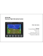
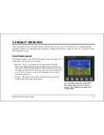
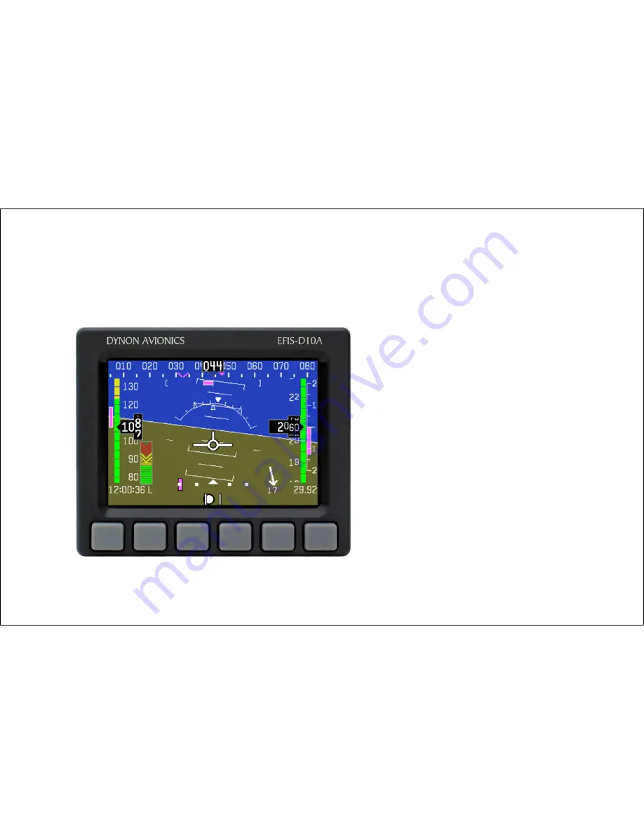
The Dynon Avionics EFIS-D10A is a cutting-edge flight instrument panel designed for general aviation aircraft. Enhance your flying experience with this advanced display, featuring a stunning glass screen and intuitive interface. For detailed instructions on how to use the EFIS-D10A, download the user manual for free from 88.208.23.73:8080.
Page 2: ......
Page 8: ...Table of Contents viii EFIS D10A Pilot s User Guide Appendix D EFIS D10A Specifications 8 8...
Page 34: ......
Page 60: ......