Dynon Avionics SkyView SV-D1000, User Manual
The Dynon Avionics SkyView SV-D1000 is an advanced aviation display system that offers unrivaled functionality and ease of use. Enhance your flying experience with this cutting-edge product by downloading its user manual for free at 88.208.23.73:8080, ensuring you make the most of its impressive features and capabilities.
Share
Download


Reviews:
No comments
Related manuals for SkyView SV-D1000

ESAGONALE MINI
Brand: VALERA Pages: 2
L3 9029000-20000
Brand: L3 Aviation Products Pages: 27

HKN KRDT-1
Brand: HURAKAN Pages: 58
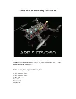
FPV250
Brand: Arris Pages: 24
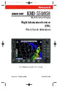
KMD 550/850
Brand: Honeywell Pages: 84
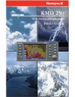
KMD 250
Brand: Honeywell Pages: 274
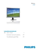
240P4
Brand: Philips Pages: 47

BDL4988XL
Brand: Philips Pages: 50

RS-CN-0468
Brand: Omcan Pages: 20

193BCR15HCB
Brand: Avantco Equipment Pages: 7

G3X Touch
Brand: Garmin Pages: 68

ClearNav
Brand: Nielsen-Kellerman Pages: 86

MotoMonitor
Brand: FLYelectronics Pages: 8


