background image

Introduction

Technical Features

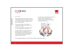
Joint Structure

Handling

Storage

Determination of Special Lengths & Offset Sizing

Installation

Points To Be Taken Into

Consideration Before Installation

Mounting Instructions For Joints

Installation of End Closer

Fire Barriers

......................................................................

...........................................................

..................................................................

.............................................................................

..............................................................................

........

...................................

....................................

................................................

.......................................................................

1.

2.

3.

4.

5.

6.

7.

7.1

7.2

7.3

7.4

2

3

4

5

6

7

8

9

11

Points To Be Taken Into

Consideration After Installation

KOP 40-80A Plastic Tap Off Boxes Installation

KOP 160-250-400A Tap Off Boxes Installation

Cable Feed Box Installation (B10, B11)

Energizing

Before Energizing

Energizing The Equipment

Maintenance

EC Decleration of Conformity

Product Overview

...............................

.......

........

...................

.......................................................

.........................................

.................................................................

....................................

.......................................................

7.5

7.6

7.7

7.8

8

8.1

8.2

9.

10.

11.

12

13

14

14

15

18

19

20

22

23

23

ENGLISH

CONTENTS

Summary of Contents for KO-II

Page 1: ...Fire Barriers 1 2 3 4 5 6 7 7 1 7 2 7 3 7 4 2 3 4 5 6 7 8 9 11 Points To Be Taken Into Consideration After Installation KOP 40 80A Plastic Tap Off Boxes Installation KOP 160 250 400A Tap Off Boxes In...

Page 2: ...ivery of equipment on site Handling installation and operation of busbar systems should be carried out only by skilled trained and authorized personnel using all associated equipment such as rubber gl...

Page 3: ...0 164 0 235 11 0 12 5 25 52 5 603 0 144 0 207 12 5 14 0 35 73 5 643 0 078 0 144 16 0 19 0 35 73 5 693 0 068 0 110 18 0 21 0 Rated Current Conductor Type Aluminium KOA Copper KOC Busbar Code KO IIMANUA...

Page 4: ...ck jointed end and a non block jointed end See as shown Figure 2 1 1 Busbar 2 2 Busbar 3 Block Joint 3 1 Locker Piece 3 2 Insulators 3 3 Double Headed Nut 3 4 Plastic Seperator Piece 4 Conductors 5 Fr...

Page 5: ...nsurance Company must be informed immediately for proper reporting with all required documents for further action 2 3 4 5 6 All busbar straight lengths and modules should be handled with care to avoid...

Page 6: ...r Storage area should be free of vehicle traffic to prevent physical damage to the products 2 When busbar straight lengths and modules are to be stored for a certain time before installation restore t...

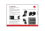
Page 7: ...e measure the lengths of these modules as shown below 2 Length A is measured between housing of 2 busbars in cm A The special length is calculated by deducting 25cm from this measured length X A 12 cm...

Page 8: ...project drawings 3 The recommended distance between supports is 2m Make sure that support positions do not block either joint covers or tap off points usbar system should be handled with care either b...

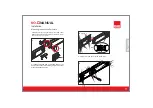
Page 9: ...arked as shall be thrown away 1a 2 Introduce bolted and non bolted ends of the busbar into each other carefully till joint side cover plate screws can be put on 3 Fix the joint side cover of the block...

Page 10: ...KO IIMANUAL 6 II Install top and bottom joint cover plates Check the joint before fitting the last joint side cover plate Fit the joint cover side plate and tighten and screws Check the position of t...

Page 11: ...nts 8 55 Nm 40lbft Installation of End Closer KO IIMANUAL 8 If removal is required for any reason tighten nut by calibrated torque wrench adjusted to 55 Nm 40 lbft after re fixing block joint set 11 E...

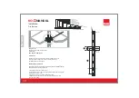
Page 12: ...Barrier KO Fire barriers are used to prevent the transition of flame and smoke from one zone to another in case of fire Chimney effect of air insulated busbars are diminished While placing an order f...

Page 13: ...tall five conductor units to four conductor units or vice versa 4 Do not apply any kind of oil or chemical at the joints or to the contacts of tap off boxes KG O il 4 8 KO IIMANUAL 5 Do not use any ot...

Page 14: ...Consideration After Installation 12 Take care when handling the system components Do not drop the units 13 Ensure the selected degree of protection IP rating of the system is suitable for the working...

Page 15: ...arth contact 3 Carefully align the tap off box contacts and push the box towards the busbar 4 When the box is secured to the busbar housing closed the box cover and tighten the screws Attention Check...

Page 16: ...ps Push left side of tap off box towards busbar and lock fixing clamps to the busbar Tight back the plastic headed bolt to hold busbar rigidly 3 Carefully align the tap off box contacts and push right...

Page 17: ...e should be checked in order to match the busbar phases sequence before reconnecting all connections to transformers switchboards meters etc 1 When installing the feeder boxes B10 B11 make sure that t...

Page 18: ...in sequence by starting at the source to end of the system 5 After all overcurrent protection devices have been turned on loads such as lighting circuits contactors heaters and motors may be turned ON...

Page 19: ...nce 1 An external inspection of the system should be carried out once a year 2 Any dripping or other source of moisture onto the busbar modules should be eliminated from installed area Contact EAE for...

Page 20: ...e responsibility that the aforementioned products conforms with the regulations and guidelines of the following standards According to EC Directive 2006 95 EEC Low Voltage Directive Tests KO IIMANUAL...

Page 21: ...ation To prevent wrong alignment of the phase sequence during installation there shall be mechanical barriers on the joint that shall ensure correct mounting IP Plug in covers of the busbar system sho...

Page 22: ...om the busbar when the switch is at ON position Mechanical interlock mechanism shall prevent the cover of the box fromopening whentheswitchisat ON position When the switch is at OFF position and the c...

Reviews: