Pub. 988-0152-011
www.eaglesonar.com
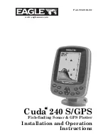
Cuda 240 S/GPS
Fish-finding Sonar & GPS Plotter
Installation and Operation
Instructions
Page 1: ...Pub 988 0152 011 www eaglesonar com Cuda 240 S GPS Fish finding Sonar GPS Plotter Installation and Operation Instructions...
Page 2: ...t necessary to change or end our policies regulations and special offers at any time We reserve the right to do so without notice All features and specifications subject to change without notice All s...
Page 3: ...Bracket Installation 16 Transducer Orientation and Fish Arches 17 Shoot Thru Hull Preparation and Installation 18 Power and Cable Connections 22 Mounting the Sonar Unit In Dash or Bracket 23 Portable...
Page 4: ...leshooting 65 Sec 6 Basic GPS Operations 69 Keyboard 69 Power Lights Turn Unit On and Off 70 Main Menu 70 Pages 72 Sonar Pages 72 Satellite Status Page 72 Navigation Page 74 Position Page 76 Plotter P...
Page 5: ...8 Delete an Icon 98 Navigate to an Icon 99 Routes 99 Create and Save a Route 99 Delete a Route 101 Edit a Route 102 Navigate a Route 102 Navigate a Route in Reverse 103 Utilities 104 Alarm Clock 104 S...
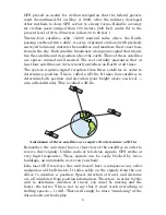
Page 6: ...wing navigation data to a position waypoint a GPS unit will show the shortest most direct path to the waypoint It provides navigation data to the waypoint regardless of obstructions Therefore the prud...
Page 7: ...concept you re already familiar with we ll show you how and where to skip ahead for the next important topic We ve also made it easy to look up any tips you may need from time to time Here s how The m...
Page 8: ...onar and GPS opera tions We describe how to use those common options along with GPS options in Section 7 System Setup and GPS Setup Options Section 7 is organized in alphabetical order Finally in Sect...
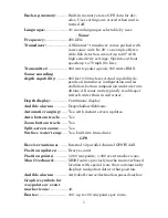
Page 9: ...ion and water con ditions All sonar units typically read deeper in fresh water than in salt water Depth display Continuous display Audible alarms Deep shallow fish zone Automatic ranging Yes with inst...
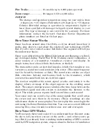
Page 10: ...al impulse which the transducer con verts into a sound wave and sends into the water The sound frequency can t be heard by humans or fish The sound wave strikes an object fish structure bottom and bou...
Page 11: ...ion of the unit s onboard memory is devoted to recording GPS navigation information which includes waypoints event marker icons trails and routes This lets you look back the way you came and retrace y...
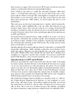
Page 12: ...ception from three satellites in order to determine a position This is called a 2D fix It takes four satellites to determine both position and elevation your height above sea level also called altitud...
Page 13: ...but terrain foliage or even large man made structures can sometimes block the WAAS signal from ground receivers You ll find that using your GPS receiver is both easy and amazingly accurate It s easil...
Page 14: ...equences Most functions you perform with this unit are described as a sequence of key strokes and selecting menu commands We ve written them in a condensed manner for quick and easy reading For exampl...
Page 15: ...wer cable from the unit s location to an appropriate power source and connect it there 6 Connect the transducer power cable to the unit and mount the so nar GPS unit to the bracket Transducer Installa...
Page 16: ...d a paper plate or piece of cardboard to mix the epoxy on Supplies rubbing alcohol 100 grit sandpaper specially formulated epoxy adhesive available from LEI see ordering information on the inside back...
Page 17: ...transducer cable away from other wiring on the boat Electrical noise from engine wiring bilge pumps and aerators can be displayed on the sonar s screen Use caution when routing the transducer cable ar...
Page 18: ...In a shoot thru hull installation the transducer is bonded to the inside of the hull with epoxy The sonar ping signal actually passes through the hull and into the water This differs from a bolt thru...
Page 19: ...if you can move the transducer so that it s parallel with the ground 1 Assembling the bracket Press the two small plastic ratchets into the sides of the metal bracket as shown in the following illustr...
Page 20: ...for the ratchets assemble the transducer as shown in the fol lowing figure Don t tighten the lock nut at this time Assemble transducer and bracket 4 Drilling mounting holes Hold the transducer and br...
Page 21: ...ducer to the transom Slide the transducer up or down until it s aligned properly with the bottom of the hull as shown in the preceding and following figures Tighten the bracket s mount ing screws seal...
Page 22: ...seal the hole with the same marine grade above or below waterline seal ant adhesive used for the mounting screws 7 Make a test run to determine the results If the bottom is lost at high speed or if no...
Page 23: ...trans ducer is ready for use Transducer mounted on trolling motor side view TRANSDUCER ORIENTATION AND FISH ARCHES If you do not get good fish arches on your display it could be because the transduce...
Page 24: ...the chosen area See the figure below WARNING Do not remove any material from your inner hull unless you know the hull s composition Careless grinding or cutting on your hull can result in damage that...
Page 25: ...the boat Plug the transducer into the sonar unit turn it on then hold the transducer over the side of the boat in the water Adjust the sensitivity and range controls until a second bottom echo is see...
Page 26: ...gnal 4 Most people can get good results by following steps 1 through 3 so this step is optional If you want to make an extra effort to be absolutely sure that your selected location will work under al...
Page 27: ...a thin layer of epoxy about 1 16 or 1 5 mm thick on the face of the transducer as shown in the previous figure Make sure there are no air pockets in the epoxy layer Then apply the remaining ep oxy to...
Page 28: ...s power socket In saltwater environments we recommend you connect the power cable to the auxiliary power switch included in most boat designs If that results in electrical interference or if such a s...
Page 29: ...evices this unit could be damaged to a point that it is unrepairable and could even cause harm to the user when not properly fused CAUTION Failure to use the enclosed 3 amp fuse will void your warrant...
Page 30: ...ounting You may need to place a piece of plywood on the back side of thin pan els to reinforce the panel and secure the mounting hardware Drill a 5 8 15 9 mm hole in the dash for the power transducer...
Page 31: ...for tilting the unit and attaching the connector The snug fit of the push on water proof connector requires some force to attach Also be sure there is enough cable slack for rotation if you decide to...
Page 32: ...of the bracket as you lower it into position As you push down the unit will lock into place with a distinct click To adjust the viewing angle pinch the ratchets with one hand then tilt the unit with...
Page 33: ...g It includes a rechargeable gel cell battery and a transducer designed for stationary use The entire rig is contained in a carry bag that fits inside a five gallon plastic bucket The PPP 12 package i...
Page 34: ...le Power Pack with a sonar unit stowed for transport Turn the unit on If it doesn t work make sure the battery terminals are making good contact against the battery contacts Also check the wiring conn...
Page 35: ...the nut onto it Screw the suction cup onto the bracket using the supplied screw and flat washer Tie the nylon cord through the hole in the top of the bracket When using this transducer tie the other e...
Page 36: ...move on to Sec 3 Basic Sonar Operations There we ll present a series of step by step tutorials to teach you the basics of your sonar operation NOTE When you first turn the unit on the GPS Plotter Pag...
Page 37: ...yboard can be found at the beginning of Sec 6 1 PWR LIGHT Power Light The PWR key turns the unit on and off and activates the backlight 2 PAGES Pressing this and the arrow keys 4 switches the unit be...
Page 38: ...otter Page zooming in lets you see greater detail in a smaller geographic area on the display Memory This unit has permanent memory that saves all user settings even when power is removed It does not...
Page 39: ...r shallow depth alarms Popup Help command one of the System Setup options turns the pop up help boxes on or off When you select a menu command these information boxes appear to tell you what the comma...
Page 40: ...ity are important basic functions that are discussed both here and in the Advanced Sonar section The other Sonar Menu commands include Grayline command separates fish and structure near the bottom fro...
Page 41: ...ptions They are the Full Sonar Chart Split Zoom Sonar Chart and Digital Data You access the various display modes by pressing the PAGES key Press to SONAR or to desired page ENT The Full Sonar Chart i...
Page 42: ...ways We ll discuss all of those features and options in the Advanced Sonar Operation section but to show you how easy the sonar unit is to operate the following page contains a simplified 10 step qui...
Page 43: ...l filter out some information but could omit important images We recommend adjusting sensitivity until the background is lightly peppered that is scattered dots ap pear but individual objects like fis...
Page 44: ...creasing the sensitivity a little at a time There are situations when too much clutter appears on the screen Decreasing the sensitivity can reduce the clutter and show the strongest fish ech oes if fi...
Page 45: ...turned on the unit will continue to track the bottom and make minor adjustments to the sen sitivity level with a bias toward the setting you selected Adjusting sensitivity in Manual Sensitivity Mode...
Page 46: ...r Fish I D fish symbol feature Here s why Fish I D is an easier way for a sonar novice to recognize a fishy signal return when he sees it However locating fish by symbol only has some limitations Your...
Page 47: ...iendly version of the tutorial available on our web site it makes a great supplement to this operation manual For the ultimate training aid be sure to download the free emulator software for your unit...
Page 48: ...42 Notes...
Page 49: ...f the transducer even vibration from the engine In all cases noise can produce unwanted marks on the display The ASP feature has four settings Off Low Medium and High If you have high noise levels try...
Page 50: ...rms The depth alarms sound a tone when the bottom signal goes shallower than the shallow alarm s setting or deeper than the deep alarm s set ting For example if you set the shallow alarm to 10 feet th...
Page 51: ...press ENT 4 Press to DEEP ALARM ENABLED ENT EXIT 5 To turn off the alarm press MENU MENU to ALARMS ENT to SONAR ALARMS ENT to DEEP ALARM ENABLED ENT EXIT To switch to a different depth setting open t...
Page 52: ...ENT EXIT EXIT EXIT To switch to a different depth setting open the Sonar Alarms menu and repeat the instructions in steps 3 and 4 above Fish Alarm Use the fish alarm for a distinctive audible alarm w...
Page 53: ...fish swims through the sonar signal cone the image appears on the screen as a long line instead of a fish arch Reducing the chart speed may result in a shorter line that more closely resembles a regul...
Page 54: ...sor line press to raise the cursor line 3 To clear the depth cursor press EXIT Depth Range Automatic When turned on for the first time the bottom signal is automatically placed in the lower half of th...
Page 55: ...nge A horizontal dark bar highlights the selected range 4 When the new range is selected press EXIT to clear the menu To turn Auto Depth Range on again 1 From the Sonar Page press MENU to AUTO DEPTH R...
Page 56: ...computer is sophisticated but it can be fooled It can t distinguish between fish and other suspended objects such as trotlines turtles submerged floats air bubbles etc Individual tree limbs ex tending...
Page 57: ...EATURES ENT 2 Press to FISH ID DEPTHS ENT EXIT EXIT To turn off FishTrack repeat these instructions Turning off FishTrack in this manner will not turn off Fish I D symbols Sonar Features menu with Fis...
Page 58: ...elected At right the Grayline control bar To adjust the Grayline level 1 From the Sonar Page press MENU to GRAYLINE ENT 2 The Grayline Control Bar appears Press to decrease Grayline press to increase...
Page 59: ...rn to the previous page press EXIT EXIT To turn off displayed data 1 Press MENU to OVERLAY DATA ENT 2 Press or to select Data Type then press ENT until the check mark to the left of the selected data...
Page 60: ...r just want the fastest possible screen update you may want to use the HyperScroll feature When you change the Ping Speed to any setting greater than 50 per cent the unit automatically enters HyperScr...
Page 61: ...tone sounds To turn off HyperScroll 1 From the Sonar Page press MENU to PING SPEED ENT 2 The Ping Speed Control Bar appears Press to decrease ping speed to 50 percent When it s set at the desired lev...
Page 62: ...Typically the best sensitivity level shows a good solid bottom signal with Colorline and some surface clutter Automatic Sensitivity The default sensitivity mode is automatic The unit bases the sensiti...
Page 63: ...o decrease sensitivity press to increase sensitivity When it s set at the desired level press EXIT When you reach the maximum or minimum limit a tone sounds At left Sonar Menu with Sensitivity command...
Page 64: ...under his keel Keel Offset lets you calibrate the digital depth indicators chart depth scale chart cursor depth and fish symbol depth displayed on the screen To calibrate the depth indicators first me...
Page 65: ...lay Options The Cuda 240 offers three Sonar chart display options To choose among them press EXIT to clear any menus then press PAGES and use the arrow keys to select the desired mode Full Sonar Chart...
Page 66: ...m range shows at the bottom left corner of the screen Split Zoom Sonar Chart Image at left shows the left window zoomed to 2X The right image shows the left window zoomed to 4X The depth overlay data...
Page 67: ...a demo mode The words demo mode in a pop up box flash in the middle of the screen and a sonar chart plays much like the simulator Unlike the simulator the demo mode is for demonstration only and will...
Page 68: ...ity control reduces or eliminates surface clutter signals from the display It does this by changing the sensitivity of the receiver decreasing it near the surface and gradually increasing it as the de...
Page 69: ...ZIN again for a 4X zoom 2 Press ZOUT to reduce the zoom and show more of the chart To turn on the Zoom Bar 1 Press MENU to SONAR FEATURES ENT 2 The Sonar Features menu appears Press to ZOOM BAR ENT E...
Page 70: ...64 Notes...
Page 71: ...mode make sure that either the transducer or the antenna is securely connected before turning the unit on Unit freezes locks up or operates erratically 1 Electrical noise from the boat s motor trollin...
Page 72: ...The technical term for this is cavitation 2 Electrical noise from the boat s motor can interfere with the sonar This causes the sonar to automatically increase its Discrimination or noise rejection f...
Page 73: ...ransducer cable away from the wiring that is causing the interference VHF radio antenna cables radiate noise when transmitting so be certain to keep the sonar s wires away from it You may need to rout...
Page 74: ...68 Notes...
Page 75: ...PWR LIGHT Power Light The PWR key turns the unit on and off and activates the backlight 2 PAGES Pressing this and the arrow keys 4 switches the unit be tween the different page screens Satellite Stat...
Page 76: ...e greater detail in a smaller geographic area on the display Power lights on and off To turn on the unit press PWR As the unit powers up the Plotter Page is displayed first To switch to another page p...
Page 77: ...igation com mands Used to stop navigating after you have reached your destina tion waypoint or plotter cursor location or after you reach the end of a route or trail Set Keel Offset command calibrates...
Page 78: ...The Sonar Pages are discussed in detail in Sec 3 To get to the Sonar Pages Press PAGES to SONAR or to page ENT Clear the Pages Menu by pressing EXIT Satellite Status Page The Satellite Status display...
Page 79: ...it isn t being used to solve the position Beneath the circular graph are the bar graphs one for each satellite in view Since the unit has twelve channels it can dedicate one channel per visible satel...
Page 80: ...tion of travel you are taking Navigation Page recording a trail traveling east Page looks like this when the unit is not navigating to a waypoint following a route or backtracking a trail When navigat...
Page 81: ...d navigating to the destination waypoint The course line is shown on the Navigation Page screen and the Plotter Page screen as a dotted line The cross track error range is shown on the compass rose as...
Page 82: ...access the Navigation Page Menu from the Navigation Page press MENU Position Page This page provides detailed textual information on your present posi tion and the status of your trip For example it c...
Page 83: ...ction you are actually travel ing Bearing is the direction of a line of sight from your present posi tion to a destination No matter what direction you are steering the Bearing shows the compass direc...
Page 84: ...ge or reduce its coverage area and the amount of detail shown There are 39 avail able zoom ranges from 0 02 miles to 4 000 miles At left Plotter Page zoomed to 30 miles note the overlapping unread abl...
Page 85: ...detail press ZIN zoom in key Zoom out to see more area less detail press ZOUT zoom out key Scroll display north south east or west using arrow keys To stop scrolling and return to current position pre...
Page 86: ...lotter other than your current position To clear the cursor press EXIT which jumps the display back to the current position or the last known position Selecting Any Plotter Item With the Cursor 1 Use...
Page 87: ...information to your destination See the following examples The Plotter Page at left clearly shows the course line connecting your current position to your destination The Navigation Page right will a...
Page 88: ...this be sure you are positioned so that the unit has as clear a view of the sky as possible then turn the unit off and back on again Find Distance From Current Position To Another Location 1 While on...
Page 89: ...nts A waypoint is simply an electronic address based on the latitude and longitude of a position on the earth A waypoint represents a location spot or destination that can be stored in memory then be...
Page 90: ...t or use the Reset Options command described in Sec 7 Create Waypoint on Plotter 1 Use the arrow keys to move the cursor to the place where you want to make a waypoint 2 Press WPT WPT The waypoint is...
Page 91: ...sition This feature sets a waypoint at a point located a specific distance and bearing from a reference position The reference position must be se lected from your waypoint list 1 Press WPT to CREATE...
Page 92: ...sired symbol and press ENT To return to the previous page press EXIT EXIT Waypoint Position To edit waypoint position 1 Press WPT ENT to waypoint name ENT to EDIT POSITION ENT 2 Latitude press to LATI...
Page 93: ...IST box by pressing ENT Use or to select the waypoint name press ENT and the waypoint information screen appears with the GO TO command se lected 4 You can use or to select various options on the wayp...
Page 94: ...ss WPT To look up the nearest waypoint just press ENT or to look by name and scroll through the entire waypoint list press to FIND BY NAME ENT For this example look by name 2 If your waypoint list is...
Page 95: ...s the ZOUT and ZIN keys at the same time Your position at the time these keys are pressed is used as the man overboard position Caution Saving a new Man Overboard waypoint will overwrite and erase the...
Page 96: ...of the current position arrow Creating and Saving a Trail The Cuda 240 is set at the factory to automatically create and record a trail while the unit is turned on The unit will continue recording th...
Page 97: ...Trail Name ENT 3 Press to ACTIVE ENT This unchecks the Active option 4 To return to the previous page press EXIT EXIT EXIT EXIT As you left the Edit Trail menu you will notice that a new trail was sta...
Page 98: ...to MY TRAILS ENT 2 Press to DELETE ALL ENT to YES ENT Display a Saved Trail The active trail is automatically displayed on the plotter the Visible option with the factory default settings You can sele...
Page 99: ...shows distance and bearing from current position to the selected point on the trail At right the Edit Trail menu Navigate a Trail There are three methods for following a trail visual trailing navigati...
Page 100: ...Tip Generally when using this method the smaller the zoom range the more accurately you will be able to steer along the trail Navigate a Trail forward The following figures illustrate the menu sequen...
Page 101: ...he trail you are navigating is represented by a flashing line The Navigation Page will also show the navigated trail as a flashing line The bearing arrow on the compass rose points to the next waypoin...
Page 102: ...is northbound heading straight toward trail point 3 bearing arrow shows the trail point straight ahead At right driver has reached trail point 3 and must turn northeast to follow the trail Arrival al...
Page 103: ...can be placed on the plotter screen saved and recalled later for navigation purposes These are sometimes referred to as event marker icons The Cuda 240 has 42 different symbols you can pick from when...
Page 104: ...Icon Symbol menu 2 Press or or or to select your icon symbol then press ENT The icon appears on the plotter Delete an Icon You can delete all the icons at one time you can delete all icons repre sent...
Page 105: ...in an ordered sequence that s used to mark a course of travel You can visualize a route as a string of beads The beads represent waypoints and the string repre sents the course of travel connecting wa...
Page 106: ...nd arrow keys to move the plotter and cursor until the cursor is centered on the waypoint or event marker icon where you want your route to begin If you are starting at your current posi tion or the c...
Page 107: ...reaches your destination 7 To save your route press EXIT The Cuda 240 reverts to the Edit Route screen with the route automatically named Route 1 and stored in the Cuda 240 s internal memory You can e...
Page 108: ...om the PLOTTER PAGE press MENU MENU to ROUTE PLANNING ENT 2 Press to route name ENT to ROUTE WAYPOINTS LIST Use and to select a waypoint then press ENT Edit Route Waypoints menu 3 Use and to select a...
Page 109: ...hat the Navigation Page and Plotter Page look like while navigating a route Navigate a Route in Reverse Here s how you run a route backward from the end waypoint to the beginning waypoint 1 From the N...
Page 110: ...heading straight for Wpt 4 which is 0 43 miles away Utilities Utilities are useful tools for traveling or for outdoor activities Alarm Clock To get to the alarm clock menu press MENU MENU to TIMERS EN...
Page 111: ...u when your track drifts too far to the right or left of the course line to the waypoint For example if the alarm is set to 0 1 mile then the alarm flashes a message if you drift 0 1 of a mile or more...
Page 112: ...rmine a position It needs this data so that it can calculate which satellites should be in view It then searches for only those satellites When your GPS receiver is turned on for the first time it doe...
Page 113: ...System Selection The Coordinate System Menu lets you select the coordinate system to use when displaying and entering position coordinates Menus for changing coordinate system used to display position...
Page 114: ...em MGRS uses two grid lettering schemes which are referred to as standard and standard 10 MGRS on this unit Your position determines which one to use If you use standard and your position is off signi...
Page 115: ...he map USGS maps are parallel others may not be Also this works better with smaller scale maps The reference position can be anywhere on the map but the closer it is to your location the smaller the n...
Page 116: ...select a different display op tion then press ENT After all options are set press EXIT to return to the page display Customize Plotter or Navigation Page While on the Plotter or Navigation pages pres...
Page 117: ...or Route Navigation In Simulator mode your unit can automatically follow a trail or route without manual steering if you use these steps 1 From the Plotter Page go to the simulator menu Pick a STARTI...
Page 118: ...his command makes the unit operate as if it is sitting someplace other than its actual location So you and your unit could be located in Kan sas City but easily practice navigating in the ocean off Is...
Page 119: ...you travel any other direction the plotter doesn t line up with your view of the world To correct this problem a track up mode rotates the plotter display as you turn Thus what you see on the left sid...
Page 120: ...lection menu right In this example we scrolled down the data list to highlight Ground Speed When selected the data type shifts to the top of the data list and a check mark appears beside the data type...
Page 121: ...layed in the new size To change the font size for another Data Type press ENT and repeat these steps be ginning with step two above 3 To return to the previous page press EXIT Tip If you wish you can...
Page 122: ...ill or moving at extremely slow speed a GPS receiver can have trouble determining the direction you are traveling In the past this resulted in a wandering plot trail that moved around the plotter even...
Page 123: ...ENU MENU to SYSTEM SETUP ENT to RESET OPTIONS ENT 2 Press or to YES ENT 3 All menus are cleared and all options are returned to factory settings System Menu with Reset Options command selected Screen...
Page 124: ...SYSTEM SETUP ENT 2 Press to SET LANGUAGE ENT 3 Use or to select a different language and press ENT All menus now appear in the language you selected Set Local Time Using the correct local time setting...
Page 125: ...is still developing the WAAS system it s not unusual for a GPS WAAS re ceiver to frequently lose and reacquire its lock on a WAAS satellite That can result in the alarm repeatedly going on and off If...
Page 126: ...urn to the last page displayed press EXIT EXIT Sounds and Alarm Sound Styles Sounds triggered by key strokes and alarms can be adjusted You first press MENU MENU to SOUNDS ENT Sounds command left At r...
Page 127: ...tion is set press EXIT EXIT to return to the page display Track Smoothing This is a factory setting on the GPS Setup menu that should always be left on When stopped or traveling at slow speeds such as...
Page 128: ...default automatic mode the unit doesn t update the plot trail while you re traveling in a straight line Once you deviate from a straight line the unit drops a plot point trail waypoint onto the trail...
Page 129: ...ress EXIT to return to the Trail Options Menu Trail Options menu Update Time Rate setting left and Update Dis tance setting right Specific Trail Options Delete Trail To delete a specific trail From th...
Page 130: ...you wish to change then press ENT Make your changes then press EXIT to erase this menu Units of Measure This menu sets the speed and distance statute or nautical miles me ters depth feet fathoms or m...
Page 131: ...onable pro tection against harmful interference in a residential installation This equipment generates uses and can radiate radio frequency energy and if not installed and used in accordance with the...
Page 132: ...126 Notes...
Page 133: ...pecifications 2 Typographical Conventions 7 K Keypad Description 7 31 69 L Languages 3 34 118 M Main Menu 32 33 44 70 71 100 103 120 122 124 Man Overboard 3 89 90 Map Fix Coordinate System 108 109 110...
Page 134: ...92 93 94 95 96 97 111 116 121 122 123 124 Delete 92 Delete All 122 Edit Name 93 Navigate 93 94 New Trail 92 123 Update Criteria 122 Update Rate 122 Trip Calculator 71 104 Trip Down Timer 104 Trip Up...
Page 135: ...e nonexclusive nonassignable right to use these Databases for supplemental navigation reference purposes but only as long as you comply with the terms and conditions of this License Agreement We reser...
Page 136: ...STANCES BE LIABLE TO ANYONE FOR ANY SPECIAL CONSE QUENTIAL INCIDENTAL OR OTHER INDIRECT DAMAGE OF ANY KIND Some states do not allow the exclusion or limitation of incidental or consequential damages s...
Page 137: ...OR REPLACEMENT OR REFUND AS JUST DESCRIBED IS THE EXCLUSIVE REMEDY AVAILABLE TO YOU AGAINST US FOR ANY DEFECT MALFUNCTION OR NON CONFORMITY CONCERNING THE PRODUCT OR FOR ANY LOSS OR DAMAGE RESULTING F...
Page 138: ...change or end our shipping policies regulations and special offers at any time We reserve the right to do so without notice in Canada If you re in Canada and you have technical return or repair questi...
Page 139: ...com 3 Canadian customers can write Lowrance Eagle Canada 919 Matheson Blvd E Mississauga Ontario L4W2R7 or fax 905 629 3118 Shipping Information If it becomes necessary to send a product for repair o...
Page 140: ...Visit our web site www eaglesonar com Eagle Pub 988 0152 011 Copyright 2003 All Rights Reserved Printed in USA 091903 Eagle Electronics...