background image

Pub. 988-0143-751 


 www.eaglesonar.com 


& FishEasy

®

 240 Portable 

Fish-Finding & Depth-Sounding Sonars 

Installation and Operation 

Instructions


Summary of Contents for FishEasy 240 Portable

Page 1: ...Pub 988 0143 751 www eaglesonar com FishEasy 240 Portable Fish Finding Depth Sounding Sonars Installation and Operation Instructions ...

Page 2: ...ons subject to change without notice All screens in this manual are simulated No part of this manual may be copied reproduced republished transmitted or distributed for any purpose without prior written consent of Eagle Electronics Any unauthorized commercial distribution of this manual is strictly prohibited For free owner s manuals and the most current information on this product its operation a...

Page 3: ...lation 16 Transducer Orientation and Fish Arches 17 Shoot Thru Hull Preparation 19 Testing Determines Best Location 20 Shoot Thru Hull Installation 22 Speed Temperature Sensors 25 Speed Sensor Installation 28 Power Connections permanent mount units only 30 Mounting the Sonar Unit In Dash Bracket or Portable 32 Bracket Installation 32 Portable Sonar Installation 37 Installing the Batteries 37 Porta...

Page 4: ...art Scroll Speed and HyperScroll 60 Noise Reject and ASP Advanced Signal Processing 61 Alarms 63 Fish Alarm 63 Depth Alarms 63 Shallow Alarm 64 Deep Alarm 64 System Setup 65 Display Adjustments 66 Backlights 66 Display Contrast 67 Depth Units of Measure 67 Temperature Units of Measure 68 Speed and Distance Log Units of Measure 69 Reset Distance Log 69 Preset Unit reset all options 70 System Info 7...

Page 5: ...t operates only in demo mode 77 Unit freezes locks up or operates erratically 77 Weak bottom echo digital readings erratic or no fish signals 78 Bottom echo disappears at high speeds or erratic digital reading or weak bottom echo while boat is moving 78 No fish arches when the Fish I D feature is off 79 Noise 79 Index 81 ...

Page 6: ...iv Notes ...
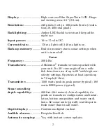
Page 7: ...unit the transducer and any optional accessories such as a speed sensor Following recommended installation practices will pay off in optimum performance of your Eagle sonar Improper installation can cause prob lems down the road especially if the transducer is badly mounted After you ve read the installation instructions install the unit and ac cessories Then read the rest of the manual The more y...

Page 8: ...r transducer comes packed with your unit Its 20 cone angle offers a wide fish detection area of up to 60º with high sen sitivity settings Operates at boat speeds up to 70 mph 61 kts Transmitter 1500 watts peak to peak power typical 188 watts RMS power typical Sonar sounding depth capability 800 feet 244 meters Actual capability de pends on transducer configuration and instal lation bottom composit...

Page 9: ...rage in temperatures higher or lower than specified will damage the liquid crystal display in your unit This type of damage is not covered by the warranty For more information contact the fac tory s Customer Service Department phone numbers are inside the manual s back cover How Sonar Works Sonar has been around since the 1940s so if you already know how it works skip ahead to the next segment on ...

Page 10: ...d bounces back to the transducer which converts the sound back into an electrical signal The receiver amplifies this return signal or echo and sends it to the display where an image of the object appears on the scrolling sonar chart The sonar s microprocessor calculates the time lapse between the transmitted signal and echo return to determine the distance to the object The whole process repeats i...

Page 11: ...its cable route 3 Determine the location of your battery or other power connection along with the power cable route 4 Install the transducer and route the transducer cable to the sonar unit 5 Route the power cable from the unit s location to an appropriate power source and connect it there 6 Connect the transducer power cable to the unit and mount the sonar unit on the bracket Installation These i...

Page 12: ...refully before attempting the installation Determine which of the mounting positions is right for your boat Use extreme care if mounting the transducer inside the hull because once it is epoxied into position the transducer usually cannot be removed Remember the transducer installation is the most critical part of a sonar installation Recommended Tools and supplies If you prefer the option of rout...

Page 13: ...ater at all times If the transducer is not placed in a smooth flow of water interference caused by bubbles and turbulence will show on the sonar s display in the form of random lines or dots whenever the boat is moving NOTE Some aluminum boats with strakes or ribs on the outside of the hull create large amounts of turbulence at high speed These boats typically have large outboard motors capable of...

Page 14: ...ference with propeller operation 5 If possible route the transducer cable away from other wiring on the boat Electrical noise from engine wiring bilge pumps and aerators can be displayed on the sonar s screen Use caution when routing the trans ducer cable around these wires Good and poor transducer locations Deadrise less than 10 Pad Strakes CAUTION Clamp the trans ducer cable to transom near the ...

Page 15: ...ing out of the water as you cross waves or wakes Move the transducer a little lower to help prevent this If you cruise or fish around lots of structure and cover your transducer may be frequently kicking up from object strikes If you wish you may move the transducer a little higher for more protection There are two extremes you should avoid Never let the edge of the mounting bracket extend below t...

Page 16: ...em on hulls that sit with the bow high when at rest or at slow trolling speeds Third a transducer CAN NOT shoot through wood and metal hulls Those hulls require either a transom mount or a thru hull installation Fourth a Skimmer transducer with a built in temp sensor will show only the temperature of the bilge not the water surface temp Follow the procedure listed in the shoot thru hull installati...

Page 17: ...st so that its face is paral lel to the ground If it does then the A position is correct for your hull If the transducer s face isn t parallel with the ground remove the transducer and ratchets from the bracket Place the ratchets into the holes in the bracket with the letter B aligned with the dot stamped in the bracket Reassemble the transducer and bracket and place them against the transom Again...

Page 18: ...ling the transducer Once you determine the correct posi tion for the ratchets assemble the transducer as shown in the following figure Don t tighten the lock nut at this time Assemble transducer and bracket Ratchets Nut Metal washer Metal washer Bolt Rubber washers ...

Page 19: ... the center of each slot for the mounting screw pilot holes You will drill one hole in the center of each slot Drill the holes Use the 29 bit for the 10 screws Position transducer mount on transom and mark mounting holes Side view shown at left and seen from above at right 5 Attaching transducer to transom Remove the transducer from the bracket and re assemble it with the cable passing through the...

Page 20: ...ly with the bottom of the hull as shown in the preceding and following figures Tighten the bracket s mounting screws sealing them with the caulking compound Adjust the transducer so that it s parallel to the ground and tighten the nut until it touches the outer washer then add 1 4 turn Don t over tighten the lock nut If you do the transducer won t kick up if it strikes an object in the water ...

Page 21: ...y the so nar Use caution when routing the transducer cable around these wires WARNING Clamp the transducer cable to the transom close to the transducer This can prevent the transducer from enter ing the boat if it is knocked off at high speed If you need to drill a hole in the transom to pass the connector through the required hole size is 5 8 If you intend to route an additional speed or temp sen...

Page 22: ...ducer bracket to go below the bottom of the hull Trolling Motor Bracket Installation single frequency only 1 Attach the optional TMB S bracket to the transducer as shown in the following figure using the hardware supplied with the transducer Note The internal tooth washer is supplied with the TMB S Attach motor mounting bracket to transducer 2 Slide the adjustable strap supplied with the TMB S thr...

Page 23: ...lack in the cable for the motor to turn freely Route the cable to the sonar unit and the transducer is ready for use Transducer mounted on trolling motor side view Transducer Orientation and Fish Arches If you do not get good fish arches on your display it could be because the transducer is not parallel with the ground when the boat is at rest in the water or at slow trolling speeds ...

Page 24: ...front of the trans ducer is too high and needs to be lowered If only the back half of the arch is printed then the nose of the transducer is angled too far down and needs to be raised Transducer aimed too far back Transducer aimed too far forward Proper transducer angle Partial fish arches Full fish arch ...

Page 25: ...rglass A successful transducer installation can be made on hulls with flotation materials such as plywood balsa wood or foam between layers of fiberglass if the material is removed from the chosen area See the figure below WARNING Do not remove any material from your inner hull unless you know the hull s composition Careless grinding or cutting on your hull can result in damage that could sink you...

Page 26: ... sonar signals Testing Determines Best Location Ideally the shoot thru transducer should be installed as close to the transom as possible close to the centerline This will give you the best performance during high speed maneuvers Shoot thru hull transducer locations for high speed or trolling speed operation 1 Anchor the boat in about 30 feet of water Add a little water to the sump of the boat Plu...

Page 27: ...m signal will probably disappear and the bottom signal intensity will likely decrease 3 Now move the transducer around to find the best location with the strongest possible bottom signal If you find a spot with an acceptable bottom signal mark the location and move on to step 4 If you can t get an acceptable bottom signal try turning up the sensitivity by three or five keystrokes and then move the...

Page 28: ...place 5 When you re satisfied with a location mark it and proceed with the installation Shoot Thru Hull Installation If you are installing the transducer on a hull with floatation material sandwiched within the hull refer to the text Hulls with Flotation Ma terials beginning on page 19 1 Make sure the area is clean dry and free of oil or grease then sand both the inside surface of the hull and the...

Page 29: ...the package and place them on the paper plate Thoroughly stir the two compounds together until the mixture has a uniform color and consistency Do not mix too fast or bubbles will form in the epoxy After mixing you have 20 minutes to complete the instal lation before the epoxy becomes unworkable Spread a thin layer of epoxy about 1 16 or 1 5 mm thick on the face of the transducer as shown in the pr...

Page 30: ...inished the face of the trans ducer should be parallel with the hull with a minimum amount of ep oxy between the hull and transducer 4 Apply a weight such as a brick to hold the transducer in place while the epoxy cures Be careful not to bump the transducer while the epoxy is wet Leave the weight in place for a minimum of three hours Allow the epoxy to cure for 24 hours before moving the boat 5 Af...

Page 31: ...E The FishEasy 240 and FishEasy 240 Portable are packed with transducers containing built in temp sensors If you want a speed sensor or an additional temp sensor see the Accessory Ordering In formation in the back of this manual If a second temp sensor is used it must be the model TS 2U This model has a fixed electronic address which designates it as the second of two temp sensors Dual temperature...

Page 32: ...ns Sonar unit with external combination speed and temperature sensor Primary temp sensor is built into transducer Temperature sensor built into transducer ST TU combination speed and temperature sensor Sonar unit rear view Power trans ducer cable 12 volt battery 3 amp fuse HST WSU ...

Page 33: ...ndary external temperature sensor Primary temp sensor is built into transducer TS 2U temperature sensor Temperature sensor built into transducer Sonar unit rear view 12 volt battery 3 amp fuse Power trans ducer cable HST WSU ...

Page 34: ...for this job include drill 5 8 drill bit 1 8 drill bit for pilot holes screwdriver Required supplies for this job include four 8 stainless steel wood screws 3 4 long high quality marine grade above or below waterline caulking compound If you intend to route the sensor cable through the same hole as the transducer cable you will need a 1 25 4 mm drill bit instead of the 5 8 drill bit Sonar unit rea...

Page 35: ...ne Once you ve determined the proper location for the unit place the sen sor on the transom The bottom of the bracket should be flush with the hull s bottom Using the sensor as a template mark the hull for the screws pilot holes Drill four 1 8 holes one in each end of the slots Mount the sensor to the hull using 8 stainless steel wood screws not included Use a high quality marine grade above or be...

Page 36: ...e make sure it is located above the waterline After installation be sure to seal the hole with the same marine grade above or below waterline seal ant used for the screws The sensor is now ready for use Connect the sensor to the accessory socket on the back of the unit If you have any questions concerning the installation of the sensor please contact your local boat dealer Power Connections perman...

Page 37: ...cable and the unit s power socket In saltwater environments we recommend you connect the power cable to the auxiliary power switch included in most boat designs If that results in electrical interference or if such a switch is not available we recommend connecting direct to the battery and in stalling an inline switch This will let you shut off power to the power cable when the unit is not in use ...

Page 38: ...our war ranty This unit has reverse polarity protection No damage will occur if the power wires are reversed However the unit will not work until the wires are attached correctly Mounting the Sonar Unit In Dash Bracket or Portable You can install the sonar unit on the top of a dash with the supplied bracket This unit can be installed in a dash with the optional FM 6 in dash adapter kit The FM 6 ki...

Page 39: ... through bolt mounting You may need to place a piece of plywood on the back side of thin pan els to reinforce the panel and secure the mounting hardware Drill a 1 25 4 mm hole in the dash for the power transducer and ac cessory cables The best location for this hole is immediately under the gimbal bracket location This way the bracket can be installed so that it covers the hole holds the cables in...

Page 40: ...e caulking compound Some marine dealers stock cable hole covers to conceal the opening Using the Quick Release Mounting Bracket These units use a quick release mounting bracket When you run the cables through the bracket s cable slots make sure you allow enough slack for tilting the unit and attaching the connector The snug fit of the push on waterproof connector requires some force to attach Mill...

Page 41: ...sory cables Then hold the sonar unit vertically and slide it onto the bracket from above The back of the unit should be touching the front of the bracket as you lower it into position As you push down the unit will lock into place with a distinct click To adjust the viewing angle pinch the ratchets with one hand then tilt the unit with your other hand Release the ratchets and the unit locks into t...

Page 42: ...onar slide the unit onto the bracket from above Adjust viewing angle use one hand to press and release the spring loaded ratchets while you move the unit with the other hand Bracket front Depress ratchets to release ...

Page 43: ...a portable power pack you simply install the batteries and then attach the sonar unit to the power pack s bracket Plug in the power transducer cable and you re ready to fish The PPP 12 has a quick release mounting bracket built into the case Installing the Batteries Release the latch on the front of the power pack case Open the com partment and install eight AA batteries into the adapter For the l...

Page 44: ...till doesn t work check the battery voltage Most of the complaints we receive about portable units result from stale batteries Make sure the ones you buy are fresh In cold weather the efficiency of dry cell batteries drops with the tem perature We find it a good idea to have the sonar unit good and warm along with the batteries before we leave home If the batteries do lose a charge you can sometim...

Page 45: ... thread the nut onto it Screw the suction cup onto the bracket using the supplied screw and flat washer Tie the nylon cord through the hole in the top of the bracket When using this transducer tie the other end of the nylon cord to the boat This will help prevent the loss of the transducer if it comes off the boat Portable transducer assembly rear view left and side view right Clean the chosen are...

Page 46: ...ansducer installed on boat transom NOTE For optimum operation the portable transducer should be adjusted so that it is parallel to the ground For more information on this see the earlier segment on Transducer Orientation and Fish Arches For more detailed instructions on installing the FishEasy 240 Portable unit please refer to the PPP 12 Porta Power Pack instruction sheet packed with your unit The...

Page 47: ... planations below Eagle FishEasy 240 Sonar showing screen and keyboard 1 PWR CLEAR power and clear This key appears in the manual text simply as PWR Press this key to turn the unit on and off It also clears menu selections and the menus from the screen NOTE You must hold the PWR key down for a countdown of five in order to turn the unit off 2 MENU UP menu up 1 2 3 ...

Page 48: ...eature and function on the sonar unit Memory This unit has permanent memory that saves all user settings even when power is removed It does not require nor does it use an internal backup battery so you never have to worry about replacement batteries Menus This unit uses menus to guide you through the various functions and fea tures Menu names and settings appear in the manual text as small capi ta...

Page 49: ...he menu will disappear after a few seconds If you don t want to wait press PWR to clear the menus from the screen When the sonar unit is first turned on and the backlight menu disap pears the display screen shows the Full Chart Page or mode The Fish I D feature is off The depth range shows on the depth scale on the right side of the screen On the screen below the range is from 0 to 60 feet and the...

Page 50: ... screen This is useful when you want to freeze the picture to study it more closely To stop or start the chart press MENU until the CHART menu appears Use the arrow keys to select or highlight the desired setting then press PWR to clear the menu Depth scale Fish arches near bait fish School of bait fish Grayline Bottom signal Thermocline Digital depth Speed Depth range at bottom of depth scale Sur...

Page 51: ...ay Modes or Pages The FishEasy 240 has three screen display modes or Pages Full Chart page Split Chart page and Large Digital page The FishEasy 240 Page menu lets you select among the display modes or pages To switch from one page to another page press MENU until the PAGE menu appears Press UP ARROW or DOWN ARROW to select the desired ...

Page 52: ...op of the screen represents the surface The bottom depth as determined by the digital sonar shows in the upper left corner Full Chart page showing digital depth at top and speed at bottom If an optional speed or temperature sensor is connected digital dis plays for speed and or temperature will also be shown Split Chart This shows the normal view of the underwater world from the surface to the bot...

Page 53: ...shows all information in big numbers The digi tal depth display is at the top of this screen followed by the tempera ture speed and distance readings NOTE Temperature speed and distance require a temperature or speed sensor These may be optional equipment depending on the sonar model you purchased Large Digital page ...

Page 54: ...ally select a range To do this press MENU until the RANGE menu appears Use the arrow keys to select the desired range When you re finished press PWR to clear the menu from the display Range Select menu This unit has the following ranges 10 15 20 30 40 60 80 100 150 200 300 500 800 and 1 000 feet Zoom The zoom feature enlarges all echoes on the screen The 2X zoom dou bles the size of the echoes on ...

Page 55: ...zoom feature off press the MENU key until the ZOOM menu appears Use the arrow keys to select OFF then press PWR to clear the menu Important Tip Your unit has the handy ability to quickly zoom in on any portion of the water column with just the touch of an arrow key The Zoom Pan feature lets you rapidly move the zoomed area up and down to different depths By pointing your zoom at different portions...

Page 56: ...e the echoes near the bottom because auto Range always keeps the bottom displayed in the lower portion of the screen When you Zoom in manual Range mode echoes are enlarged near the middle of the displayed range For example with a manual depth Range of 100 feet your screen shows the water column from zero at the top of the screen to 50 feet in the middle to 100 feet at the bottom of the screen Sele...

Page 57: ... increasing the sensitivity a little at a time There are situations when too much clutter appears on the screen Decreasing the sensitivity can reduce the clutter and show the strongest fish ech oes if fish are present As you change the sensitivity setting you can see the difference on the chart as it scrolls ...

Page 58: ... 2 Sensitivity set at 50 percent Fig 3 Sensitivity set at 20 percent Fig 4 Sensitivity set at 100 percent You can change the sensitivity level whether you are in Auto Sensitiv ity mode or Manual Sensitivity mode The adjustment method works the same in both modes but it gives you slightly different results Fig 3 Fig 4 Bait school Thermo cline with fish Fish arches Fig 1 Fig 2 ...

Page 59: ...ting with auto turned on the unit will continue to track the bottom and make minor ad justments to the sensitivity level with a bias toward the setting you se lected Adjusting sensitivity in Manual Sensitivity Mode is similar to driving a car without cruise control you have complete manual control of the car s speed In your unit manual mode allows you to set sensitivity at 100 percent maximum or z...

Page 60: ...ode above Grayline Grayline lets you distinguish between strong and weak echoes It paints gray on targets that are stronger than a preset value This al lows you to tell the difference between a hard and soft bottom For ex ample a soft muddy or weedy bottom returns a weaker signal which is shown with a narrow or no gray line A hard bottom returns a strong signal which causes a wide gray line If you...

Page 61: ...reen Center little Grayline indicates a soft bottom probably sand or mud At right the wider Grayline indicates a harder rocky bottom Fish I D The Fish I D feature identifies targets that meet certain conditions as fish The microcomputer analyses all echoes and eliminates surface clutter thermoclines and other signals that are undesirable In most instances remaining targets are fish The Fish I D fe...

Page 62: ...ween fish and other suspended objects such as trotlines turtles submerged floats air bubbles etc Individual tree limbs extending outward from a group of limbs are the hardest objects for the Fish I D feature to distinguish from fish To see what s under your boat in maximum detail we recommend you turn off Fish I D and begin learning to interpret fish arches You may see Fish I D symbols on the scre...

Page 63: ...hear it Fish I D can also be useful when you want to screen out some of the so nar detail gathered by your unit For example it can help cut through the clutter of suspended bubbles caused by wave action or boat wakes To turn Fish I D on press MENU until the FISH ID menu appears Press UP ARROW to select ON then press PWR To turn it back off repeat the above steps but press DOWN ARROW to select OFF ...

Page 64: ...h 10 levels of gray tones Normal operation with FishReveal turned off shows the weakest ech oes as black and the strongest in light gray Since all weak echoes are black fish arches show boldly against the white background The drawback is that all weak echoes such as thermoclines are also accentuated This can make it hard to distinguish fish signals inside thermoclines or other cover Fish I D symbo...

Page 65: ...white and the strongest echoes are black Echoes in between vary in gray in proportion to their signal strength In Inverted FishReveal mode the weakest echoes are black and the strongest echoes are white Again echoes in between vary in gray in proportion to their signal strength In all modes the Grayline control determines the range for black to white At left standard FishReveal mode Right Inverted...

Page 66: ...e stationary or drifting very slowly You may sometimes achieve bet ter images as you slow down the chart speed to match how fast you are moving across the bottom Switching to a scroll speed faster than 60 percent can be helpful when running at high speed Any setting greater than 60 switches the unit to HyperScroll This feature scrolls the echoes at an extremely high rate of speed giving you the ma...

Page 67: ...utter When you turn HyperScroll off you can return to your original sensitivity level Adjust scroll speed by pressing MENU until SCROLL SPEED appears Press UP ARROW to increase it and press DOWN ARROW to decrease it Press PWR to clear the menu To return to the original setting repeat the above steps but use the arrow keys to set the speed at 60 percent before clearing the menu Noise Reject and ASP...

Page 68: ...her controls Noise Reject menu The ASP feature has four settings Off Low Medium and High When first turned on noise rejection is set on low If you have high noise levels try using the medium or high ASP setting However if you are having trouble with noise we suggest that you take steps to find the interference source and fix it rather than continually using the unit with the high ASP setting There...

Page 69: ...ENU DOWN until FISH ALARM appears Press DOWN ARROW to select OFF then press PWR to clear the menu Repeat the above steps to turn the alarm back on but press UP ARROW to select ON before clearing the menu Fish Alarm menu Depth Alarms The depth alarms are triggered only by the bottom signal No other echoes will activate these alarms The depth alarms consist of a shal low and a deep alarm The shallow...

Page 70: ...h goes shallower than the alarm s setting an alarm tone sounds and a message box appears on the screen Press UP ARROW to silence the alarm This turns the alarm sound off until the shallow alarm is triggered again To turn the alarm off press MENU DOWN repeatedly until SHALLOW ALARM appears Press DOWN ARROW until the words OFF FEET appear then press PWR to clear the menu Deep Alarm To set the deep a...

Page 71: ... triggered again To turn the alarm off press MENU DOWN repeatedly until DEEP ALARM appears Press DOWN ARROW until the words OFF FEET appear then press PWR to clear the menu System Setup To customize the display press MENU DOWN until the SYSTEM SETUP menu appears then press UP ARROW The display contrast units of measure temperature and system information screens are all under this menu The Contrast...

Page 72: ...Adjustments Backlights The display is backlit for night use To turn the backlight on or off press MENU repeatedly until the BACK LIGHT menu appears Press UP ARROW to turn the light on or the DOWN ARROW to turn it off Backlight menu ...

Page 73: ...key to increase screen contrast The bar graph in the Contrast menu box shows a graph of the contrast The screen will also show the effects of the change If you reach the maximum or minimum level a tone sounds alerting you to the limits Press the PWR key to clear the menu Display Contrast menu Depth Units of Measure This unit can show the depth in feet fathoms or meters To change the depth units of...

Page 74: ... if a temperature sensor is attached in degrees Fahrenheit or Celsius To change the unit of measure press MENU DOWN until the SYSTEM menu appears Press UP ARROW then press MENU until the TEMPERATURE menu appears Use the arrow keys to select the measurement unit then press PWR to clear the menu Temperature unit of measure menu ...

Page 75: ...il the SYSTEM menu appears Press UP ARROW then press MENU until the SPEED LOG menu appears Use the arrow keys to select the desired measurement unit then press PWR to clear the menu Speed menu Reset Distance Log You can reset the distance log to zero with this command Press MENU DOWN until SYSTEM appears then press UP ARROW Press MENU until the RESET LOG menu appears Press UP ARROW and the log ret...

Page 76: ... you have changed several settings and want to return the unit to basic automatic operation Press MENU DOWN until SYSTEM appears then press UP ARROW Press MENU DOWN until the PRESET UNIT menu appears Press UP ARROW and the unit will turn itself off and reset all options Turn the unit back on by pressing PWR Preset Unit menu resets all options to the factory settings ...

Page 77: ...gnal with fish signals This lets you practice with the unit as if you were on the water all features and functions of the unit are usable A message appears occasionally to remind you that the simulator is on To use the simulator press DOWN MENU repeatedly until the SYSTEM menu appears then press UP ARROW Press DOWN MENU until the SIMULATOR menu appears Now press UP ARROW to turn it on and press PW...

Page 78: ... at tached The simulator will continue to function normally Chart Setup The Chart Setup menu lets you further customize the display The size of the digital numbers for the depth temperature speed and distance log can be customized from this menu The depth scales shown on the right side of the screen can be modified and the Fish Reveal modes can be turned on or off To enter the Chart Setup menu seq...

Page 79: ... off and this should fit most freshwater fishing situations High boat speed and slow ping speed caused by the deeper bottom can reduce the screen refresh rate This in turn can reduce the amount of detail seen on the sonar chart Try this command only if you are in deep water traveling at high speed and notice a reduction in detail on the sonar chart When Limit Search is turned on the digital sonar ...

Page 80: ...s where the LIMIT SEARCH menu appears Press UP ARROW to turn it on and press PWR to clear the menu Limit Search menu To turn Limit Search off repeat the above steps but press the DOWN ARROW to select Off Also remember to switch the depth range setting back to automatic This will restore the digital sonar s ability to auto matically track the bottom Digital Data Size for Depth Temperature Speed and...

Page 81: ...gh the list and display the desired menu then use the ARROW keys to select the desired number size or turn the numbers off Press the PWR key to clear the menus Menus for changing digital number size Scales The depth scale between the upper and lower limit on the right side of the screen can be turned on or off The default is on ...

Page 82: ...OWN until CHART SETUP appears then press UP ARROW Press MENU DOWN until SCALES appears then press DOWN ARROW to select UPPER LOWER ONLY Press the PWR key to clear the menus To turn scale on press MENU DOWN until CHART SETUP appears then press UP ARROW Press MENU DOWN until SCALES appears then press UP ARROW to select SHOW INTERMEDIATE Press the PWR key to clear the menus ...

Page 83: ... If it isn t the wiring to the unit is defective the battery terminals or wiring on the terminals are corroded or the bat tery needs charging Unit operates only in demo mode 1 The transducer has not yet been connected or has been disconnected To leave demo mode make sure the transducer is securely connected before turning the unit on Unit freezes locks up or operates erratically 1 Electrical noise...

Page 84: ...nate weaker signals such as fish or even structure from the display 3 The water may be deeper than the sonar s ability to find the bottom If the sonar can t find the bottom signal while it s in the automatic mode the digital sonar display will flash continuously It may change the range to limits far greater than the water you are in If this hap pens place the unit in the manual mode then change th...

Page 85: ... feature It is much easier to display fish arches when zoomed in on a small range of water than a large one For example you will have much better luck seeing fish arches with a 30 to 60 foot range than a 0 to 60 foot range This enlarges the targets allowing the dis play to show much more detail 4 The boat must be moving at a slow trolling speed to see fish arches If the boat is motionless fish sta...

Page 86: ...If no noise displays on the sonar unit from electrical equipment then make certain everything except the sonar unit is turned off then start the engine Increase the RPM with the gearshift in neutral If noise appears on the display the problem could be one of three things spark plugs alternator or tachometer wiring Try using resistor spark plugs alternator filters or routing the sonar unit s power ...

Page 87: ...54 Fish Symbols 42 54 FishReveal 56 FishTrack 55 Frequency 6 H HyperScroll 58 I Installation 9 26 31 35 36 37 38 Introduction Specifications 5 P Page Displays 44 Digital Data 72 Ping Speed HyperScroll 58 Power 6 9 10 33 34 35 36 37 38 39 40 41 53 75 76 77 78 Product Specifications 5 R Range 24 25 42 46 47 48 49 57 71 72 76 77 Route 9 12 18 19 20 27 31 33 75 78 S Sensitivity 24 41 49 50 51 52 77 Si...

Page 88: ...7 14 19 28 29 30 31 Transducer 5 6 7 9 10 11 12 13 14 15 16 17 18 19 20 21 22 23 24 25 26 27 29 30 31 36 37 38 60 70 75 76 77 78 Mounting 14 20 Shoot Thru Hull 23 U Units of Measure 65 66 67 Z Zooming 7 47 48 49 77 Zoom Pan 48 ...

Page 89: ...R REPLACEMENT OR REFUND AS JUST DESCRIBED IS THE EXCLUSIVE REMEDY AVAILABLE TO YOU AGAINST US FOR ANY DEFECT MAL FUNCTION OR NON CONFORMITY CONCERNING THE PRODUCT OR FOR ANY LOSS OR DAMAGE RESULTING FROM ANY OTHER CAUSE WHATSOEVER WE WILL NOT UNDER ANY CIRCUMSTANCES BE LIABLE TO ANYONE FOR ANY SPECIAL CONSEQUENTIAL INCIDENTAL OR OTHER INDIRECT DAMAGE OF ANY KIND Some states do not allow the exclus...

Page 90: ...hange or end our shipping policies regulations and special offers at any time We reserve the right to do so without notice in Canada If you re in Canada and you have technical return or repair questions please contact the Factory Customer Service Department Before any product can be returned you must call customer service to determine if a return is necessary Many times customer service can resolv...

Page 91: ...becomes necessary to send a product for repair or replacement you must first receive a return authorization number from Customer Service Products shipped without a return authorization will not be accepted When shipping we recommend you do the following 1 Please do not ship the knobs or mounting bracket with your unit 2 If you are sending a check for repair please place your check in an envelope a...

Page 92: ...Visit our web site www eaglesonar com Eagle Pub 988 0143 751 Copyright 2004 All Rights Reserved Printed in USA 102604 LEI Eagle ...

Reviews: