background image

Pub. 988-0143-811

                www.eaglesonar.com

FishStrike 2000


 &

SeaChamp 2000


 CDF

Fish-finding Sonars & Mapping GPS

Installation and Operation

Instructions

®

®

Summary of Contents for FishStrike 2000

Page 1: ...Pub 988 0143 811 www eaglesonar com FishStrike 2000 SeaChamp 2000 CDF Fish finding Sonars Mapping GPS Installation and Operation Instructions ...

Page 2: ...of Navionics Inc eXitSource Database copyright 2001 2003 Zenrin Co Ltd Exit Authority and eXitSource are trademarks of Zenrin Co Ltd Eagle Electronics may find it necessary to change or end our policies regulations and special offers at any time We reserve the right to do so without notice All features and specifications subject to change without notice All screens in this manual are simulated On ...

Page 3: ...ducer Location 12 How low should you go 14 Shoot thru hull vs Transom Mounting 15 Transom Transducer Assembly And Mounting 15 Shoot thru hull Installation 25 Speed Temperature Sensors 27 Optional Speed Sensor Installation 28 GPS Antenna Receiver Module Installation 30 NMEA 0183 Cable Connections 30 Power Connections 31 Mounting the Unit Bracket or In Dash 33 MMC or SD Memory Card Installation 36 O...

Page 4: ... Noise Rejection 66 Overlay Data 66 Overlay Data Style 69 Ping Speed HyperScroll 70 Reset Options 72 Reset Water Distance 72 Set Keel Offset 72 Sensitivity Auto Sensitivity 74 Sonar Chart Mode 75 Sonar Page Sonar Chart Display Options 76 Full Sonar Chart 76 Split Zoom Sonar Chart 77 Split Frequency Sonar Chart 77 Digital Data Display 78 Customize Page Displays 79 Map With Sonar Split Screen 80 Son...

Page 5: ...est 109 Creating and Saving a Trail 110 Displaying a Saved Trail 111 Navigating Trails 112 Visual Trailing 112 Navigate a Trail 112 Transfer Custom Maps and GPS Data Files 114 Custom Maps 114 GPS Data files 115 Cancel Navigation 116 Section 7 Advanced GPS Operations 117 Find Distance from Current Position 117 Find Distance from Point to Point 117 Icons 117 Create Icon on Map 118 Create Icon at Cur...

Page 6: ...MMC Files and Storage Space 130 Communications Port Configuration 131 Configure NMEA 131 Coordinate System Selection 132 Map Fix 133 Customize Page Displays 134 GPS Simulator 135 Simulating Trail or Route Navigation 136 Hide GPS Features 137 Initialize GPS 137 Map Auto Zoom 137 Map Data 138 Earth Map Detail 138 Pop up Map Info 138 Draw Map Boundaries 138 Fill Water with White 139 Trackline Extensi...

Page 7: ... Smoothing 159 Trail Options 160 Delete All Trails 160 Update Trail Option 160 Update Trail Criteria Auto Time Distance 161 Trail Update Rate Time Distance 161 Specific Trail Options 161 Delete Trail 161 New Trail 162 Units of Measure 162 Sec 9 Searching 165 Find Addresses 165 Find Any Item Selected by Map Cursor 168 Find Interstate Highway Exits 168 Find Map Places or Points of Interest POI 171 F...

Page 8: ...ing to a waypoint but will also visually check to make sure a clear safe path to the waypoint is always available WARNING When a GPS unit is used in a vehicle the vehicle operator is solely responsible for operating the vehicle in a safe manner Vehicle operators must maintain full surveillance of all pertinent driving boating or flying conditions at all times An accident or collision resulting in ...

Page 9: ...ading the manual So we designed our book so you don t have to read the whole thing from front to back to find the information you want At the start or end of each segment we ll tell you what content is coming up next If it s a concept you re already familiar with we ll show you how and where to skip ahead for the next important topic We ve also made it easy to look up any tips you may need from ti...

Page 10: ...ents flipping through Section 6 or scanning through the command portion of Section 7 This unit is ready to use right out of the box but you can fine tune and customize its operation with dozens of options Since sonar is the unit s key feature we put the main sonar options in Section 4 Some options such as screen brightness settings affect both sonar and GPS operations We describe how to use those ...

Page 11: ...en unit is turned off Languages 10 menu languages selectable by user Sonar Frequency Depending on transducer either 50 200 kHz dual frequency SeaChamp 2000C DF only or 200 kHz single frequency Transducers Skimmer transducer with built in temperature sensor available Use either a dual frequency transducer with 35 12 cone angles SeaChamp 2000C DF only or a single frequency transducer with a 20 cone ...

Page 12: ...s Metro areas selected major streets highways and interstate exit services details included Custom mapping MapCreate 6 software optional optional plug and play LEI FreedomMaps offer the same high detail without the computer work of MapCreate Other plug and play mapping options include Fishing Hot Spots Elite LEI NauticPaths charts and Navionics charts Mapping memory Up to 1 GB on one MMC or SD car...

Page 13: ...s or fish The sound wave strikes an object fish structure bottom and bounces back to the transducer which converts the sound back into an electrical signal The receiver amplifies this return signal or echo and sends it to the display where an image of the object appears on the scrolling sonar chart The sonar s microprocessor calculates the time lapse between the transmitted signal and echo return ...

Page 14: ...e moving map shown on the screen The whole process takes place several times a second The performance doesn t stop there Stored in the permanent memory of every unit is a basic background map of the entire world We lock it in here at the factory you can t change or erase this map The background map is suitable for many navigation chores but for maximum accuracy and much more detail you need our op...

Page 15: ...Custom Map Files file format lcm can also be shared between other Eagle GPS or sonar GPS units and personal computers For example the exact same MMC custom map files and GPS data files can be used interchangeably between your gimbal mounted unit and the hand held iFINDER GPS receiver The unit automatically reads Custom Map Files directly from the MMC or SD card To use a custom map all you need to ...

Page 16: ...required to determine a 2D fix The system requires signal reception from three satellites in order to determine a position This is called a 2D fix It takes four satellites to determine both position and elevation your height above sea level also called altitude This is called a 3D fix Remember the unit must have a clear view of the satellites in order to receive their signals Unlike radio or telev...

Page 17: ...quator so they appear very low in the sky to someone on the ground in North America Aircraft and vessels on open water can get consistently good WAAS reception but terrain foliage or even large man made structures frequently block the WAAS signal from ground receivers You ll find that using your GPS receiver is both easy and amazingly accurate It s easily the most accurate method of electronic nav...

Page 18: ... to select are show in italic type such as trail name Instructions Menu Sequences Most functions you perform with this unit are described as a sequence of key strokes and selecting menu commands We ve written them in a condensed manner for quick and easy reading For example instructions for navigating a trail would look like this 1 From the Map Page press MENU MENU to MY TRAILS ENT 2 Press to Trai...

Page 19: ...the transducer cable to the sonar GPS unit 6 Install the GPS antenna and route the antenna cable to the sonar GPS unit 7 Install the power cable and route it to the sonar GPS unit 8 Connect the cables to the unit and mount the unit on the bracket Transducer Installation These instructions will help you install your Skimmer transducer on a transom on a trolling motor or inside a hull These instruct...

Page 20: ... bit flat head screwdriver Supplies high quality marine grade above or below waterline sealant adhesive compound Dual frequency transom installations Tools two adjustable wrenches drill 20 0 161 drill bit flat head screwdriver Supplies four 1 long 12 stainless steel slotted wood screws high quality marine grade above or below waterline sealant adhesive compound Single frequency trolling motor inst...

Page 21: ...at hulls have a flat keel pad that offers a good mounting surface On vee hulls try to place the transducer where the deadrise is 10 or less Left vee pad hull right vee hull A pod style transducer is shown here but the principle is the same for Skimmers inside a hull 4 If the transducer is mounted on the transom make sure it doesn t interfere with the trailer or hauling of the boat Also don t mount...

Page 22: ...the transducer may be coming out of the water as you cross waves or wakes Move the transducer a little lower to help prevent this If you cruise or fish around lots of structure and cover your transducer may be frequently kicking up from object strikes If you wish you may move the transducer a little higher for more protection There are two extremes you should avoid Never let the edge of the mounti...

Page 23: ...sonar display This is not an issue for flasher style sonars Lack of angle adjustment can be particularly troublesome on hulls that sit with the bow high when at rest or at slow trolling speeds Third a transducer CAN NOT shoot through wood and metal hulls Those hulls require either a transom mount or a thru hull installation Fourth if your Skimmer transducer has a built in temp sensor it will only ...

Page 24: ... into the sides of the plastic bracket and two on either side of the transducer as shown in the following illustrations Notice there are letters molded into each ratchet Place the ratchets into the bracket with the letter A aligned with the alignment mark molded into the bracket Place the ratchets onto the transducer with the letter A aligned with the 12 o clock position on the transducer stem The...

Page 25: ...cer s face isn t parallel with the ground remove the transducer and ratchets from the bracket Place the ratchets into the holes in the bracket with the letter B aligned with the dot stamped in the bracket Reassemble the transducer and bracket and place them against the transom Again check to see if you can move the transducer so it s parallel with the ground If you can then go to step 3A If it doe...

Page 26: ...ed with the bracket alignment mark Place them on the transducer aligned with the 12 o clock position on the transducer stem Reassemble the transducer and bracket and place them against the transom Again check to see if you can move the transducer so it s parallel with the ground If you can then go to step 3B If it doesn t repeat step 2B but use a different alignment letter until you can place the ...

Page 27: ...ot for the mounting screw pilot holes You will drill one hole in the center of each slot Drill the holes For the one piece bracket use the 29 bit for the 10 screws For the two piece bracket use the 20 bit for the 12 screws Position transducer mount on transom and mark mounting holes Side view shown left and seen from above right 5 Attaching transducer to transom A One piece bracket Remove the tran...

Page 28: ...om to the sonar unit Make sure to leave some slack in the cable at the transducer If possible route the transducer cable away from other wiring on the boat Electrical noise from the engine s wiring bilge pumps VHF radio wires cables and aerators can be picked up by the sonar Use caution when routing the transducer cable around these wires WARNING Clamp the transducer cable to the transom close to ...

Page 29: ...e internal tooth washer is supplied with the TMB S Attach motor mounting bracket to transducer 2 Slide the adjustable strap supplied with the TMB S through the slot in the transducer bracket and wrap it around the trolling motor Position the transducer to aim straight down when the motor is in the water Tighten the strap securely 3 Route the transducer cable alongside the trolling motor shaft Use ...

Page 30: ...ck half of the arch is printed then the nose of the transducer is angled too far down and needs to be raised NOTE Periodically wash the transducer s face with soap and water to remove any oil film Oil and dirt on the face will reduce the sensitivity or may even prevent operation SHOOT THRU HULL PREPARATION Hulls With Floatation Materials The transducer installation inside a fiberglass hull must be...

Page 31: ...for 24 hours fill the remaining space with polyester resin When the job is finished the hull is watertight and structurally sound Remember the sonar signal must pass through solid fiberglass Any air bubbles in the fiberglass or the epoxy will reduce or eliminate the sonar signals WARNING Do not remove any material from your inner hull unless you know the hull s composition Careless grinding or cut...

Page 32: ...Depth Range and ASP Try a range setting that is two to three times the water depth The harder more rocky the bottom the easier it will be to get a second bottom signal Don t touch the controls once they ve been set Example of a second bottom signal Unit is in 30 feet of water with range set at 80 feet and sensitivity set at 87 percent 2 Next take the transducer out of the water and place it in the...

Page 33: ...at your selected location will work under all conditions make a test run with the boat on plane and observe the bottom signal You ll need to figure some way to prop the transducer into position while you make your test run A brick or two might be sufficient to hold it in place 5 When you re satisfied with a location mark it and proceed with the installation Shoot thru hull Installation If you are ...

Page 34: ...s shown in the previous figure Make sure there are no air pockets in the epoxy layer Then apply the remaining epoxy to the sanded area on the hull 3 Press the transducer into the epoxy twisting and turning it to force any air bubbles out from under the transducer face Stop pressing when you bottom out on the hull When you re finished the face of the transducer should be parallel with the hull with...

Page 35: ...vice NOTE This unit is packed with a transducer containing a built in temp sensor The SeaChamp package also includes a speed sensor If you have a FishStrike 2000c and want a speed sensor or additional temp sensor see the Accessory Ordering Information in the back of this manual If a second temp sensor is used it must be the model TS 2U This model has a fixed electronic address which designates it ...

Page 36: ... drill bit for pilot holes screwdriver Required supplies for this job include four 8 stainless steel wood screws 3 4 long high quality marine grade above or below waterline caulking compound First find a location on the boat s transom where the water flow is smoothest Don t mount the sensor behind strakes or ribs These will disturb the water flow to the speed sensor Make sure the sensor will Sonar...

Page 37: ...view showing good location for mounting sensor on transom If the base of the transom has a radius fill the gap between the transom and the sensor with the sealing compound This will help ensure a smooth water flow Speed sensor mounting configuration side view left and rear view right Route the sensor s cable through or over the transom to the sonar unit If you need to drill a hole in the transom t...

Page 38: ...od results by simply placing the external antenna on the top of the dash at the base of the windshield a piece of the rubber non skid shelf liner material available in recreational vehicle supply stores will help hold the antenna in place This may not work well if you have a cab over design pickup truck camper or motor home If dashboard reception is poor simply relocate the antenna module elsewher...

Page 39: ...that you shut off the power supply to the power cable when the unit is not in use When the unit is turned off but still connected to a power supply electrolysis can occur in the power cable plug This may result in corrosion of the plug body along with the electrical contacts in the cable and the unit s power socket In saltwater environments we recommend you connect the power cable to the auxiliary...

Page 40: ...r FishStrike 2000c and SeaChamp 2000C DF sonar GPS units WARNING This product must be independently fused with the enclosed 3 amp fuse or equivalent even if you connect to a fused accessory or power buss If a malfunction happens inside the unit extensive damage can occur if the enclosed fuse is not used As with all electrical devices this unit could be damaged to a point that it is unrepairable an...

Page 41: ...s the unit s gimbal bracket to a swivel mount which can be used on the dash or overhead mounting positions Optional R A M mounting system Bracket Installation Mount the unit in any convenient location provided there is clearance behind the unit when it s tilted for the best viewing angle You should also make sure there is enough room behind the unit to attach the power transducer and GPS antenna r...

Page 42: ...the back side of thin fiberglass panels to reinforce the panel and secure the mounting hardware Install the gimbal bracket Place the bracket so the arms slope toward the front of your unit Once a location is determined use the bracket as a template and mark the mounting holes and the hole for the cables Drill a 1 inch 25 4 mm Front Screw mounting hole Cable hole Millimeter Inch 244 9 58 94 3 61 56...

Page 43: ...hole around the cables with a good marine caulking compound No matter what type of installation you prefer be sure to leave enough slack in the cables to allow tilting or swiveling the unit Attach the unit to the gimbal bracket using the supplied gimbal knobs and washers Attach the cables and the unit is ready to use In Dash Installation You can mount the unit in the dash with an optional FM 3 In ...

Page 44: ...e in storage capacities of 8 MB 16 MB 32 MB 64 MB 128 MB and higher SD cards are available in capacities of 8 MB 16 MB 32 MB 64 MB 128 MB 256 MB and 1 GB Additional MMC cards are available from LEI Extras see ordering information inside the back cover of this manual MMCs and SD cards are also available at many camera and consumer electronics stores The MMC drawer is located on the front of the cas...

Page 45: ...r of this manual Visit our web site for a complete listing of all the available accessories for your unit Now that you have your unit installed move on to Sec 3 Basic Sonar Operations In Sec 3 we ll present a series of step by step tutorials to teach you the basics of your sonar operation NOTE When you first turn the unit on the Map Page appears If you d rather start learning about GPS operation f...

Page 46: ...38 Notes ...

Page 47: ...betical order Before you turn on the unit it s a good idea to learn about the different keys the Main Menu the four Page screens and how they all work together BUT if you just can t wait to get on the water turn to the one page Quick Reference on page 47 Keyboard FishStrike 2000 sonar GPS unit front view showing sonar screen keyboard and access door for the MMC compartment 1 PWR LIGHT Power Light ...

Page 48: ...used to save recall and search for waypoints but also provides access to the waypoint list It launches the Point of Interest POI search menus and is involved in some navigation functions 8 ZOUT Zoom Out This key lets you zoom out the sonar display On the Sonar Page it returns you to a full sonar chart display showing the entire water column from surface to bottom On the Map Page the ZOUT key allow...

Page 49: ... and return to the page display press EXIT Remember our text style for MENU MENU means press the Menu key twice See a full explanation of our instruction text formatting on page 9 Instructions Menu Sequences Main Menu The Main Menu commands and their functions are Screen changes the contrast or brightness of the display Sounds enables or disables the sounds for key strokes and alarms and sets the ...

Page 50: ...hen using or to select a Page Clear the Pages Menu by pressing EXIT Pages Menu showing sonar display options Satellite Status Page The Satellite Status Page provides detailed information on the status of the unit s satellite lock on and position acquisition To get to the Satellite Status Page press the PAGES key then use or to select STATUS Clear the Pages Menu by pressing EXIT This page represent...

Page 51: ... EXIT This page represents a GPS function so it is discussed in much greater detail in Sec 6 Navigation Page left navigation with sonar right Map Page The Map Page screens show your course and track from a bird s eye view on a moving map By default this unit shows the map with north always at the top of the screen The arrow in the center of the screen is your present position It points in the dire...

Page 52: ...nar Page The Sonar Page displays the sonar chart This is a cross section view of the water column beneath the boat The chart moves across the screen displaying sonar signal echoes that represent fish structure and the bottom To get to the Sonar Page Press the PAGES key then use or to select SONAR Clear the Pages Menu by pressing EXIT The Pages Menu offers four chart display options under the Sonar...

Page 53: ... sonar display left with digital data display right Sonar Page showing full sonar chart mode Surface clutter Structure Bottom signal Fish arches In FasTrack fish arches show as horizontal bars Depth scale Digital data overlay depth temperature Surface signal Zoom bar FasTrack bar graph ...

Page 54: ...tter interpret the underwater scene We ll discuss all of those features and options in Sec 4 but to show you how easy the unit is to operate the following page contains a simplified 10 step quick reference that will cover most fish finding situations The quick reference describes how your unit will operate with all the sonar features in their automatic modes ...

Page 55: ...e lower portion of the screen The full sonar chart will scroll from right to left showing you what s under the boat as you cruise across the water You can change the display by Zoom in to enlarge the chart for more detail press ZIN Zoom out to return to full chart mode press ZOUT 7 Watch the display for the appearance of fish arches When you see arches you ve found fish Stop the boat and get your ...

Page 56: ...ations when too much clutter appears on the screen Decreasing the sensitivity can reduce the clutter and show the strongest fish echoes if fish are present As you change the sensitivity setting you can see the difference on the chart as it scrolls These figures show results of different sensitivity levels on the same location Fig 1 Sensitivity at 88 percent Typical of full auto mode Fig 2 Sensitiv...

Page 57: ...r without cruise control you have complete manual control of the car s speed In this unit manual mode allows you to set sensitivity at 100 percent maximum or zero percent minimum Depending on water conditions the bottom signal may completely disappear from the screen when you reduce sensitivity to about 50 percent or less Try adjusting sensitivity in both auto and manual modes to see how they work...

Page 58: ...layed as fish could be tree limbs or turtles To see what s under your boat in maximum detail we recommend you turn off Fish I D and begin learning to interpret fish arches Fish I D is most handy when you re in another part of the boat or performing some task that prevents you from watching the sonar screen Then you can turn on Fish I D and the audible fish alarm When that lunker swims under your b...

Page 59: ...s like a Windows Multimedia Player with forward reverse pause fast forward fast reverse and scroll buttons Adjustments update the entire record displayed Windows can dynamically be sized on your monitor Mouse cursor shows GPS position depth and sounding number anywhere on the visible record For the ultimate training aid be sure to download the free emulator software for your unit Aside from being ...

Page 60: ... eaglesonar com The emulator works exactly like your real sonar GPS unit It allows you to play back sonar logs run GPS routes and trails and even create real waypoints you can use in the field You can also take snapshots of the Sonar Chart and print them or e mail them to friends ...

Page 61: ...gine In all cases noise can produce unwanted marks on the display The ASP feature has four settings Off Low Medium and High If you have high noise levels try using the High ASP setting If however you are having trouble with noise we suggest you take steps to find the interference source and fix it rather than continually using the unit with a high ASP setting There are times when you may want to t...

Page 62: ... the deep alarm s setting For example if you set the shallow alarm to 10 feet the alarm will sound a tone if the bottom signal is less than 10 feet It will continue to sound until you steer your boat into water deeper than 10 feet The deep alarm sounds a warning tone if the bottom depth is deeper than the alarm s setting Both depth alarms work off digital bottom depth signals No other targets will...

Page 63: ... Alarms menu with Adjust Zone command selected left Adjust Zone Alarm selection box with Upper Limit selected right 3 To set the upper boundary for the Zone Alarm use or to select UPPER then press or to move the top of the bar to the desired depth 4 To set the lower boundary for the Zone Alarm use or to select LOWER then press or to move the bottom of the bar to the desired depth 5 Press EXIT to Z...

Page 64: ...peed sensor s performance is to compare its reading with the ground speed measured by your unit s GPS When you compare your GPS ground speed to speed sensor speed perform your test in relatively calm water free of current if possible Unless of course you are taking the current speed into consideration when making your calculation After you have a correct figure here s how to enter it 1 Press MENU ...

Page 65: ...f you experiment with chart speed remember to reset it to maximum when you resume trolling or moving across the water at higher speed To change chart speed 1 From the Sonar Page press MENU to CHART SPEED ENT 2 The Chart Speed Control Bar appears Press to decrease chart speed or to increase chart speed 3 When it s set at the desired level press EXIT ColorLine ColorLine lets you distinguish between ...

Page 66: ...ish from structure ColorLine is adjustable Experiment with your unit to find the ColorLine setting that s best for you Sonar Page menu with ColorLine command selected left The ColorLine control bar right To adjust the ColorLine level 1 From the Sonar Page press MENU to COLORLINE ENT 2 The ColorLine Control Bar appears Press to decrease ColorLine or to increase Colorline 3 When it s set at the desi...

Page 67: ...re near the left structure but the display shows fish holding next to the structure on the right Depth Cursor The depth cursor consists of a horizontal line with a digital depth box on the right side The numbers inside the box show the depth of the cursor ColorLine Muddy bottom Hard bottom Muddy bottom Fish near structure Hard bottom Hard structure Colorline Colorline Fig 2A Fig 3A Fig 2B Fig 3B F...

Page 68: ...ursor line or to raise the cursor line 3 To clear the depth cursor press EXIT Depth Range Automatic When turned on for the first time the bottom signal is automatically placed in the lower half of the screen This is called Auto Ranging and is part of the automatic function You can change the bottom setting to a different depth depending upon the bottom depth and the current range To do this 1 From...

Page 69: ...ghlights the selected range 4 When the new range is selected press EXIT to clear the menu NOTE The sonar s depth capability depends on the transducer installation water and bottom conditions among other factors FasTrack This feature automatically converts all echoes to short horizontal lines on the display s far right side FasTrack gives you a rapid update of conditions directly under the boat Thi...

Page 70: ...s air bubbles etc Individual tree limbs extending outward from a group of limbs are the hardest objects for the Fish I D feature to distinguish from fish You may see fish symbols on the screen when actually there are no fish The reverse also is true Does that mean Fish I D is broken No It is simply interpreting sonar returns in a specific way to help take some of the work out of reading the screen...

Page 71: ...only when the Fish I D feature is on The default setting for FishTrack is off To turn on FishTrack Note These instructions will turn on FishTrack and Fish I D at the same time 1 From the Sonar Page press MENU to SONAR FEATURES ENT 2 Press to FISH DEPTHS ENT EXIT EXIT To turn off FishTrack repeat the instructions in step 1 Turning off FishTrack in this manner will not turn off Fish I D symbols Fish...

Page 72: ...out 80 percent of the fresh and salt water sport fishing applications When you get into very deep salt water 300 to 500 feet or deeper the 50 kHz frequency is the best choice The 200 kHz transducer will give you better detail and definition but less depth penetration The 50 kHz transducer will give you greater depth penetration but a little less detail and less definition Remember all sonar units ...

Page 73: ...ss EXIT EXIT to clear the menu HyperScroll See the entry on Ping Speed which controls the HyperScroll feature Log Sonar Chart Data If you have an MMC installed in the unit the sonar data shown on the screen can be saved and played back at any time To play a recorded sonar chart log see the entry in this section for Sonar Simulator If you have a personal computer and internet access download our fr...

Page 74: ...ferent commands Select FILE NAME if you want to change the name Select CHART QUALITY if you want to lower the file quality so you can record for a longer period of time After you ve changed the settings select START LOGGING Noise Rejection See the entry on Advanced Signal Processing in this section Overlay Data On any page display except the Satellite Status and Navigation pages you can float or o...

Page 75: ...me can be collapsed to hide its contents Just select the category and press ENT 3 Expand categories that might contain data you want to display Then press or to select a data option 4 With the data option highlighted press ENT to check it turn it on or uncheck it turn it off As you turn it on the data will appear on top of the screen Every Page display has a maximum number of items you can show us...

Page 76: ...tion 4 When satisfied press EXIT EXIT NOTE The Customize command and the Overlay Data command use the same information categories The difference between the two commands is the Customize command is only used to modify pages with digital data boxes while Overlay Data changes information floating on the screen See Customize Page Displays on page 79 for information on customizing data boxes To change...

Page 77: ...splayed for that data type Overlay Data Style Do you like a digital readout or do you prefer an analog gauge look With the Overlay Style feature you can mix and match your data to suit your viewing preferences To access overlaid data style menu 1 Press MENU to OVERLAY DATA ENT 2 This will bring up the Overlay Data Shown menu with a list of current overlay data Highlight the data you want to change...

Page 78: ...egory on the setup menu then press ENT To return to the main sonar display press ENT repeatedly For advanced information on Overlay Data Style skip ahead to page 151 Ping Speed HyperScroll Ping Speed controls the rate at which the transmitter and transducer broadcast sonar sound waves pings into the water The unit has a default ping speed of 50 percent At normal boating speeds this automatically p...

Page 79: ...vel that eliminates the clutter When you turn HyperScroll off you can return to your original sensitivity level Sonar Menu with Ping Speed command selected left The Ping Speed Control Bar right at default setting To change Ping Speed 1 From the Sonar Page press MENU to PING SPEED ENT 2 The Ping Speed Control Bar appears Press to increase ping speed or to decrease ping speed When it s set at the de...

Page 80: ...et Options dialog box right NOTE Reset Options does not erase any waypoints routes plot trails or sonar logs Reset Water Distance The sonar chart s Digital Data display option includes a window that shows distance traveled called Water Distance W Distance This information is calculated from an optional water speed sensor not the GPS The Water Distance window can be reset to zero using the Reset Wa...

Page 81: ...n the water than it really is 1 Press MENU MENU to SONAR SETUP ENT 2 Use to scroll down to KEEL OFFSET then press ENT The Keel Offset dialog box appears Press to change the plus sign to a minus sign 3 Press to the first number then press to change the number to 3 4 Press to the second number then press to change the number to 5 then press EXIT The depth indicators now accurately show the water dep...

Page 82: ...tuations when it becomes necessary to increase or decrease sensitivity This typically happens when you want to see more detail which requires a boost in sensitivity But when wave action and boat wakes clutter the screen with tiny air bubbles a decrease in sensitivity is necessary The control bar used to adjust sensitivity up or down is the same whether the unit is in the automatic or manual mode I...

Page 83: ...he factory setting Tip For quicker sensitivity adjustments try leaving the Sensitivity Control Bar on the screen as the chart scrolls You can see the changes on the screen as you press the up and down arrows This is handy when there s a lot of clutter in the water and you are matching the sensitivity to rapidly changing water conditions Sonar Chart Mode The default color scheme for the sonar chart...

Page 84: ...left Depth scales on the right side of the screen aid in determining the depth of targets The line at the top of the screen represents the surface The bottom depth and surface temperature if equipped with a temperature sensor or a transducer with a temp sensor built in show at the top left corner of the screen The FasTrack display shows just to the right of the scale This changes all echoes into s...

Page 85: ...ght side The zoom range shows at the bottom left corner of the screen Split Zoom Sonar Chart Image left shows the left window zoomed 2X The image on the right shows the left window zoomed 4X Split Frequency Sonar Chart Dual Frequency Transducers only This page option shows sonar data from the 50 kHz transducer element on the left side of the screen and data from the 200 kHz transducer on the right...

Page 86: ...hen press ENT 3 The Sensitivity Control Bar appears Press to decrease sensitivity press to increase sensitivity When it s set at the desired level press EXIT When you reach the maximum or minimum limit a tone sounds The Split Frequency Sonar Chart page allows you to adjust sensitivity separately for each window Digital Data Display This mode displays five digital data boxes on the left side of the...

Page 87: ...isions are only there to help you sort through the information To change information displayed in a data box On a page with digital data boxes press MENU to CUSTOMIZE ENT A data box on the display will flash indicating it is selected Press ENT to modify the box or hit or to select another box then press ENT You ll see a list of categories with or symbols next to each category A category with a is ...

Page 88: ... with the map on the left and the sonar on the right This screen option can be found on the Pages Menu under the Map Page category Map with Sonar split screen When this screen is activated you need to specify which side of the Menu is active To toggle between the two windows press PAGES PAGES The window with the blue title bar at the top of the screen is the active window To switch back press PAGE...

Page 89: ... water 3 Turn off the Sonar Simulator by pressing MENU MENU to SONAR SETUP ENT to SONAR SIMULATOR ENT EXIT Sonar Page playing a recorded sonar chart in Sonar Simulator mode Tip The Sonar Simulator can use sonar charts recorded logged on a MMC card To see how read the entry in this section on Log Sonar Chart Data To play a sonar chart make sure the MMC containing the chart is installed then 1 Press...

Page 90: ...r the demo mode is for demonstration only and will automatically stop as soon as you turn on the unit with a transducer attached The simulator will continue to function normally Stop Chart If you are running multiple units on a boat or using this unit in a car there are times when you may want to turn off the sonar The Stop Chart command turns off the sonar and stops the chart from scrolling Sonar...

Page 91: ... adjust the Surface Clarity level 1 From the Sonar Page press MENU to SONAR FEATURES ENT Sonar Features menu with Surface Clarity selected 2 Press to SURFACE CLARITY ENT 3 Press or to select the clarity level then press EXIT EXIT EXIT In the illustration on the left Surface Clarity is turned off The view on the right shows Surface Clarity set on high Zoom Zoom Bar Zooming in is a common fast and e...

Page 92: ...nly the echoes between the top and bottom of the 4X bar will show on the screen Press the Zoom Out key ZOUT to return the display to the normal mode Sonar page zoomed 2X left The same view zoomed 4X right Zoom Pan Your unit has the handy ability to quickly zoom in on any portion of the water column with just the touch of an arrow key The Zoom Pan feature lets you rapidly move the display up and do...

Page 93: ...ansducer or the antenna is securely connected before turning the unit on Unit freezes locks up or operates erratically 1 Electrical noise from the boat s motor trolling motor or an accessory may be interfering with the sonar unit Rerouting the power and transducer cables away from other electrical wiring on the boat may help Route the sonar unit s power cable directly to the battery instead of thr...

Page 94: ...vitation 2 Electrical noise from the boat s motor can interfere with the sonar This causes the sonar to automatically increase its Discrimination or noise rejection feature This can cause the unit to eliminate weaker signals such as fish or even structure from the display Try using resistor spark plugs or routing the sonar unit s power and transducer cables away from other electrical wiring on the...

Page 95: ...ransducer cable away from the wiring that is causing the interference VHF radio antenna cables radiate noise when transmitting so be certain to keep the sonar s wires away from it You may need to route the sonar unit s power cable directly to the battery to isolate it from other wiring on the boat If no noise displays on the sonar unit from electrical equipment then make certain everything except ...

Page 96: ...88 Notes ...

Page 97: ... turn on the unit and find where you are it s a good idea to learn about the different keys the four Page screens and how they all work together BUT if you just can t wait to get outside turn to the one page Quick Reference on page 100 Keyboard SeaChamp 2000 sonar GPS unit showing map with sonar screen keyboard and access door for MMC compartment The map is a Nautic Path nautical chart 1 PWR LIGHT...

Page 98: ...oints It not only gives you access to the waypoints list but also launches the Point of Interest POI search menus and is involved in some navigation functions 8 ZOUT Zoom Out This key lets you zoom out the map display On the Sonar Page the ZOUT key returns you to a full sonar chart display showing the entire water column from surface to bottom On the Map Page it lets you see a larger geographic ar...

Page 99: ...ommands and their functions are Screen changes the contrast or brightness of the display screen Sounds enables or disables the sounds for key strokes and alarms and sets the alarm style Alarms turns GPS or sonar alarms on or off and changes alarm thresholds Route Planning used to plan view or navigate a route My Trails shows hides creates and deletes plot trails Also used to navigate or backtrack ...

Page 100: ...he screen from right to left displaying signal echoes that represent fish structure and the bottom The Sonar Page is discussed in detail in Sec 3 To get to the Sonar Page press the PAGES key then use or to select SONAR Clear the Pages Menu by pressing EXIT Satellite Status Page The Satellite Status Page shown provides detailed information on the status of the unit s satellite lock on and position ...

Page 101: ...raph are the bar graphs one for each satellite in view Since the unit has twelve channels it can dedicate one channel per visible satellite The taller the bar on the graph the better the unit is receiving the signals from the satellite The Estimated Position Error horizontal position error shown in the upper left corner of the screen is the expected error from a benchmark location In other words i...

Page 102: ...stead Closing Speed is also known as velocity made good It s the speed you re making toward the waypoint For instructions see the Customize Page Display entry in Sec 8 Track is the heading the current direction you are actually traveling Bearing is the direction of the line of sight from your present position to the destination No matter what direction you are steering the Bearing window shows the...

Page 103: ...ns and for setting various options Options and setup are discussed in Sec 8 To access the Navigation Page Menu from the Navigation Page press MENU Map Page The Map Page screens show your course and track from a bird s eye view By default this unit shows the map with north always at the top of the screen This can be changed See the topic Map Orientation in Sec 8 If you re navigating to a waypoint t...

Page 104: ...ile zoom range left with a few Point of Interest icons visible Numerous Points of Interest dots become visible at the 3 mile range center along with minor streets At the 0 6 mile zoom range right you can see an interstate highway with an exit major and minor streets as well as Point of Interest icons Background map vs MapCreate map content The background map includes low detail maps of the whole w...

Page 105: ... are in MapCreate When the map is zoomed out far enough most POIs appear as square dots left As you zoom in closer the symbols become readable icons In the 0 6 mile zoom example right the cursor has selected the Cupps Café POI which triggers a pop up box with the POI name This pop up box works on POIs at any zoom range Tip In some urban areas businesses are so close to one another their POI icons ...

Page 106: ...ue bar at the top may be modified with the cursor keyboards and menus Only one window may be modified at a time Resize Window is another handy feature for pages that have two major windows You can change the horizontal size of the windows to suit your viewing preference Here s how 1 From any two window display press MENU to RESIZE WINDOW ENT 2 Two flashing arrows appear along the centerline dividi...

Page 107: ... you want to revert to the factory default Map Menu with Resize Window command selected left Pressing moves the centerline and enlarges the left window right The following page contains a 12 step quick reference for the most basic GPS operations If you don t want to carry the manual with you as you practice with the unit you might consider photocopying this quick reference page and tucking it into...

Page 108: ...d the map by Zoom in closer to see greater detail press ZIN zoom in key Zoom out to see more area less detail press ZOUT zoom out key Scroll map north south east or west using arrow keys To stop scrolling and return to current position on map press EXIT key 6 Set a waypoint Wpt 001 at your current position so you can navigate back to it Press WPT WPT Waypoint symbol and 001 appears 7 Zoom scroll m...

Page 109: ...om in to move in closer and see greater detail in a smaller geographic area 2 Press the ZOUT key zoom out to move farther away and see less map detail but a larger geographic area When you are traveling the map will automatically move as you move This keeps your current location roughly centered on the screen You can manually pan or scroll the map northward southward eastward or westward by using ...

Page 110: ...d restaurant For more information on different types of searches refer to Sec 9 Searching NOTE This example requires the Point of Interest POI database included with a high detail MapCreate 6 custom map After the unit has acquired a position 1 Press WPT to POI RESTAURANTS 2 You could search the entire restaurant category but in this example we will narrow our search Press to SUBCATEGORY column to ...

Page 111: ... see it on the map so press to FIND ON MAP ENT POI information screen on the nearest fast food restaurant showing name street address phone number latitude longitude distance and compass bearing The Go To command is selected left The figure on the right has the Find On Map command highlighted 6 The unit s map appears with the cross hair cursor highlighting the restaurant s POI symbol A pop up name...

Page 112: ...recalled for navigational purposes While you are navigating you can create a waypoint at the cursor position on the map or at your current position A waypoint can be created at any location by manually entering the position s latitude and longitude It is also possible to copy waypoints from your unit to your personal computer with MapCreate software When you want to repeat a trip these archived wa...

Page 113: ...oint Symbol is described in Sec 7 After you have changed a waypoint symbol the unit will remember the one you chose and use it the next time you quick save a waypoint To revert back to the default symbol edit a waypoint and choose it or use the Reset Options command described in Sec 8 Create Waypoint on Map 1 Use the arrow keys to move the cursor to the place where you want to make a waypoint 2 Pr...

Page 114: ...ct any waypoint visible on the Map Page with the cursor then use the Navigate to Cursor command which will be covered later in this section You can avoid scrolling the map to pick your waypoint if you use the Find Waypoint commands 1 Press WPT to SAVED ENT To look up the nearest waypoint press to NEAREST ENT or to look by name and scroll through the entire waypoint list just press ENT For this exa...

Page 115: ...the same time Your position at the time these keys are pressed is used as the man overboard position Caution Saving a new Man Overboard waypoint will erase the previous Man Overboard waypoint Navigate Back to MOB Waypoint Find your way back to the accident position with the Navigation Page or Map Page When MOB is activated the Navigation Page automatically shows the compass rose with its bearing a...

Page 116: ... GO TO CURSOR command navigates to the current cursor position on the map It s a quick and handy way to navigate to anything you can see on the map display 1 Use the cursor controlled by the arrow keys with the zoom in and zoom out keys to maneuver around the map until you find a location you d like to visit 2 Center the cursor over the location to select it See the example in the following figure...

Page 117: ...ht shows current position and direction to destination on screen To stop navigating to the cursor use the Cancel Navigation command Press MENU MENU to CANCEL NAVIGATION ENT to YES ENT The unit stops showing navigation information Navigate to a Point of Interest POIs in view on the map can be located easily by using the Navigate to Cursor command above Just use the cursor to select the POI The othe...

Page 118: ... 9 999 points long When the point limit is reached the unit begins recording the trail over itself By default the trail flashes once a second making it easier to see against the background map With the default auto setting the unit creates a trail by placing a dot trail point on the screen every time you change directions The methods used for creating a trail and the trail update rate can be adjus...

Page 119: ...u can save and recall up to 10 different plot trails which can be copied to your MMC for archiving or transferred to your MapCreate software Tip Another quick way to stop recording one trail and begin a new one is to use the New Trail command Press MENU MENU to MY TRAILS ENT ENT Caution You also have the option of completely turning off trail recording under the trail Options command If the Update...

Page 120: ...ge The only difference between them is navigating a trail follows a trail forward from start to end while backtracking follows a trail in reverse When hiking at walking speed with a hand held GPS we often use visual back trailing because it is a bit better at following each little turn on a footpath At faster speeds like driving or boating the Navigate Trail and Backtrack Trail commands are handy ...

Page 121: ...stination be sure to cancel navigation Press MENU MENU to CANCEL NAVIGATION ENT The unit asks if you re sure press ENT Navigate a trail menu sequence Fig 1 My Trails command Fig 2 Trails Menu Fig 3 Edit Trail Menu Fig 4 Edit Route Menu with Navigate command highlighted for Trail 6 A trail is always converted to a route when you navigate the trail On the Map Page a course line represents the trail ...

Page 122: ...il NOTE If you are already located at or near the end of your trail the arrival alarm will go off as soon as you hit ENT Just press EXIT to clear the alarm and proceed 5 Now begin moving and let your GPS guide you 6 When you reach your destination be sure to cancel navigation Press MENU MENU to CANCEL NAVIGATION ENT The unit asks if you re sure press ENT Transfer Custom Maps and GPS Data Files Cus...

Page 123: ...NU MENU to SYSTEM SETUP ENT to TRANSFER MY DATA ENT and the screen below appears The Transfer My Data submenu asks if you want to save data to the MMC or load data from the MMC into the unit s memory 2 The Transfer My Data menu includes a message that tells you if a MMC is present or not If no MMC is present you must insert a card into the unit to activate the Load or Save commands To transfer dat...

Page 124: ... to activate the MMC Card selection box use or to highlight the file then press ENT Next press to LOAD ENT The unit will display a completion message when the data transfer is finished To return to the Page view press EXIT EXIT EXIT These figures show the menu sequence for loading a GPS Data File from an MMC into the unit s memory Cancel Navigation You can turn off any of the navigation commands a...

Page 125: ...ure distance between two other points on the map 1 While on the Map Page press MENU to FIND DISTANCE ENT 2 Center your cursor over the first position A rubber band line appears connecting your current position to the cursor s location Press ENT to set the first point and the rubber band line disappears 3 Move the cursor to the second position The rubber band line reappears connecting the first poi...

Page 126: ...elect Icon Symbol menu 3 Use or or or to select your icon symbol then press ENT The icon appears on the map Select Icon Symbol menu left Boat Ramp icon on map right Cursor has been moved for clarity Create Icon at Current Position 1 While you are traveling press ENT and the screen shows the Select Icon Symbol menu 2 Press or or or to select your icon symbol then press ENT The icon appears on the m...

Page 127: ...navigate to the icon press MENU ENT Follow course line on the Map Page or the compass bearing arrow on the Navigation Page Routes A route is a series of waypoints linked together in an ordered sequence to mark a course of travel You can visualize a route as a string of beads The beads represent waypoints and the string represents the course of travel connecting waypoint to waypoint The course from...

Page 128: ...he MMC in the unit See Sec 2 for instructions on installing MMCs To load the GPS Data File into the Unit memory see the entry on Transfer Custom Maps GPS Data Files in Sec 6 Basic GPS Operations Routes Created in the Unit You can create a route by selecting saved waypoints from the waypoint list or you can set a series of route waypoints on the map with cursor arrows and the ENT key In this exampl...

Page 129: ...1 Set route waypoint 1 at 11th St 145th Ave Fig 2 Move cursor north to set point 2 at 145th Admiral Fig 3 With point 2 set move cursor east to mark interstate on ramp with waypoint 3 In figures 2 and 3 notice the rubber band line extending from the previously set waypoint to the cursor This line will become the course for the route Route creation sequence continued Fig 4 Point 3 set at on ramp Fig...

Page 130: ...ess ENT 3 Press to NAVIGATE then to DELETE ENT to YES ENT Tip You can also delete all routes at once 1 From the NAVIGATION PAGE with digital data press MENU ENT or from the MAP PAGE press MENU MENU to ROUTE PLANNING ENT 2 Press to DELETE ALL ENT to YES ENT Edit a Route You can edit the route name if you wish 1 From the NAVIGATION PAGE with digital data press MENU ENT or from the MAP PAGE press MEN...

Page 131: ... will delete the waypoint from the route View Waypoint will show you where the selected waypoint is on the map Navigate a Route 1 From the NAVIGATION PAGE with digital data press MENU ENT or from the MAP PAGE press MENU MENU to ROUTE PLANNING ENT Routes menu left and the Edit Route menu right with the Navigate command selected 2 Press to select Saved Route pick a route and press ENT to NAVIGATE EN...

Page 132: ...straight for the waypoint 11 In Fig 2 the traveler has arrived at the destination and the arrival alarm has been triggered Trails Delete a Trail This is the procedure used to delete a trail Press MENU MENU to MY TRAILS ENT to trail name ENT to DELETE TRAIL ENT to YES ENT Tip You can also delete all trails at once 1 Press MENU MENU to MY TRAILS ENT 2 Press to DELETE ALL ENT to YES ENT Edit a Trail ...

Page 133: ... To edit a trail color press MENU MENU to MY TRAILS ENT to trail name ENT to COLOR ENT Press or to select a style then hit ENT Press EXIT EXIT EXIT EXIT to return to the previous page display Edit a Trail Pattern To edit a trail pattern press MENU MENU to MY TRAILS ENT to trail name ENT to PATTERN ENT Press or to change the first character then press to the next character and repeat until the patt...

Page 134: ...Up Timer menu press MENU MENU to TIMERS ENT ENT Waypoints Delete a Waypoint To delete a waypoint from the waypoint list press WPT ENT ENT ENT to waypoint name ENT to DELETE WAYPOINT ENT to YES ENT To delete a waypoint from the map 1 Use the arrow keys to select the waypoint with the cursor 2 Press WPT to DELETE WAYPOINT ENT to YES ENT To return to the previous page and clear the cursor press EXIT ...

Page 135: ...e longitude is correct Press EXIT 4 When latitude and longitude are correct return to the previous page press EXIT EXIT EXIT EXIT Selecting a Waypoint To select a waypoint on the map for navigating editing etc use the arrow keys and center the cursor over the waypoint A highlighted halo will appear around the waypoint Set a Waypoint by Average Position This feature sets a waypoint at the current p...

Page 136: ...re or Point of Interest When the point has been selected press ENT and the point s position appears as the reference position 4 Press to DISTANCE ENT Press or to change the first character then press to the next character and repeat until the distance is correct Press ENT 5 Press to BEARING ENT Press or to change the first character then press to the next character and repeat until the bearing is ...

Page 137: ...ile then the alarm flashes a message if you drift 0 1 of a mile or more to the right or left of the line to the waypoint The anchor alarm is triggered when you drift outside of a preset radius Again using the 0 1 mile as an example if you re anchored and your boat moves more than 0 1 mile the alarm will flash a message and sound a tone GPS Alarms highlighted left GPS Alarms menu right To change al...

Page 138: ...r GPS receiver is turned on for the first time it doesn t know what your position or elevation altitude is It does know the current UTC time and date since they were programmed into it at the factory An internal clock keeps the time while the unit is turned off If the time and or date are incorrect you can set it using the Set Local Time menu The unit begins searching for the satellites using data...

Page 139: ...configuring the unit to communicate with another device consult the factory Customer service phone numbers are in the back of this manual Also see the entry below on how to Configure NMEA To set Com Port Configuration 1 Press MENU MENU to SYSTEM SETUP ENT 2 Press to COMMUNICATIONS PORT ENT Configure NMEA You can configure the unit to use specific NMEA sentences 1 Press MENU MENU to SYSTEM SETUP EN...

Page 140: ... Mercator projection MGRS Standard MGRS Standard 10 Map Fix Loran TD British Irish Finnish German New Zealand Swedish Swiss Taiwan Greek and Military grids UTM s are marked on USGS topographic charts This system divides the Earth into 60 zones each 6 degrees wide in longitude British Irish Finnish German New Zealand Swedish Swiss Taiwan and Greek grid systems are each the national coordinate syste...

Page 141: ...used with charts or maps This system asks for a reference position in latitude longitude which you take from a marked location on the map It then shows the present position as distance on the map from that reference point For example if it shows a distance of UP 4 00 and LEFT 0 50 you then measure up four inches and to the left a half inch from the reference point on the map to find your location ...

Page 142: ...XIT and the unit returns to the Configure Map Fix screen Configure a map fix so the unit can find your position on a printed chart or topographical map Press to SELECT ORIGIN WAYPOINT ENT Press to saved then press ENT ENT ENT Use or to choose a saved waypoint Select the waypoint you saved the reference point under and press ENT The unit displays a waypoint information screen with SET AS ORIGIN sel...

Page 143: ...ata category expanded Selecting the category name and pressing ENT will show the category s contents so you can choose items within it An expanded category one with a next to its name can be collapsed to hide its contents Just select the category name and press ENT Expand categories that may contain data you want to display Then press or to select a different data option With the new option highli...

Page 144: ... using the STEER WITH ARROWS command you can press EXIT to clear the steering and speed boxes from the screen This will allow you to use the map cursor during a simulation To turn steering and speed boxes back on again return to the GPS Simulator menu Select the STEER WITH ARROWS command press ENT then EXIT Simulating Trail or Route Navigation In Simulator mode your unit can automatically follow a...

Page 145: ...perate as if it is sitting someplace other than its actual location So you and your unit could be located in Kansas City but practice navigating in the ocean off Islamorada Florida 1 With the GPS simulator off press MENU MENU to GPS SETUP ENT ENT 2 A message appears telling you to move the cursor near the desired location and press ENT When the message automatically clears follow the message instr...

Page 146: ... menu For instructions see the Navionics Charts entry in this section To get to Map Data From the Map Page press MENU to MAP DATA ENT Map Menu left Map Data Menu right Earth Map Detail From the Map Page press MENU to MAP DATA ENT Press ENT to check to select the level of map detail you prefer Use to choose off low medium or high then press EXIT to the page display Pop up Map Info From the Map Page...

Page 147: ...trol over the map layout by allowing you to choose between US and International Modes Safety Contour From the Map Page press MENU to MAP DATA ENT Press and to SAFETY CONTOUR ENT Use to choose the desired depth and press ENT The SAFETY CONTOUR command allows you to modify depth contours on a navionics map for water less than 10 meters deep Based on your preferences the depth contours will be colore...

Page 148: ...T EXIT to return to the page display Map Datum Selection Maps and charts are based on a survey of the area that s covered by the map or chart These surveys are called Datums Maps that are created using different datums will show the same latitude longitude in slightly different locations All datums have names The GPS system is based on the WGS 84 datum which covers the entire world Other datums ma...

Page 149: ... To return to the last page displayed press EXIT EXIT Map Menu left Map Categories Drawn Menu right Map Orientation By default this receiver shows the map with north always at the top of the screen This is the way most maps and charts are printed on paper Map orientation is shown in north up left and track up right This is fine if you re always traveling due north What you see to your left corresp...

Page 150: ...ss MENU to MAP ORIENTATION ENT Use or to select the desired mode then press ENT Press EXIT EXIT to return to the page display Map Orientation menu with the North Up map option selected right Navionics Charts Your unit can display Navionics electronic charts on MMCs They work just like a MapCreate custom map on a MMC Entrance to Chesapeake Bay in a MapCreate 6 custom map with a 15 mile zoom left Th...

Page 151: ... NAVIONICS MAP CHOICE ENT Use or to select EAGLE then press ENT EXIT EXIT Port Information Navionic charts contain Port Services information represented by anchor icons on the map display An example is displayed in the following figure To view Port Services information 1 Use the arrow keys to move the cursor over a Port Services icon When selected a pop up name box appears 2 Press WPT to display t...

Page 152: ...IES press to DETAILED SERVICES ENT then use or to read the list of available services return to the Map Page press EXIT EXIT To return to the top service category window press ENT Port Services information screens Tidal Current Information Navionics charts contain Tidal Current information represented at large zoom ranges by a box icon with the letter C The icon stands for a Tidal Current Station ...

Page 153: ...al Current Information screen Navionics chart showing Tidal Current Station icon selected by cursor The current is flowing to the west at 0 1 mph Current Information screen The Tidal Current Information screen displays daily tidal current data for the station at the present time The graph at the top of the example above is an approximate view of the flood and ebb pattern from midnight MN to noon N...

Page 154: ...ormation Navionics charts contain Tidal Information represented at large zoom ranges by a box icon with the letter T The icon stands for a Tidal Station location An example is displayed in the figure on the right When you zoom in to a sufficiently small zoom range the icon itself becomes an animated gauge showing a rising or falling tidal height for the selected station At larger zoom ranges you c...

Page 155: ...tation at the present time The graph at the top of the screen is an approximate view of the tidal range pattern for the day from midnight MN to noon NN to midnight MN The dotted line across the graph is the Mean Lower Low Water line MLLW The height scale on the top right side of the graph changes based upon the maximum range of the tide for that day The MLLW line also adjusts its position as the h...

Page 156: ... could show your bearing course average speed and trip distance The various data available from your unit are divided into categories in the Overlay Data menu These categories include GPS Data Navigation Trip Calculator Time Sonar Data and Miscellaneous Data You can select items from any of these categories for display in any combination the category divisions are there only to help you sort throu...

Page 157: ...has a maximum number of items you can show using the Overlay Data command 5 After the desired changes are made press EXIT EXIT to return to the page display From Overlay Data Shown menu left press ENT to see Data Viewer right Bearing has been selected from the Navigation category To remove overlaid data 1 While on the Page that shows the item or items you want to remove press MENU to OVERLAY DATA ...

Page 158: ...ress EXIT EXIT NOTE The Customize command and the Overlay Data command both use the same information categories The difference between the two commands is that Customize changes only the data boxes on a screen and Overlay Data changes only the information floating on the screen without a box See Customize Page Displays on page 79 for information on customizing data boxes To change displayed data f...

Page 159: ...r data to suit your viewing preferences To access overlaid data style menu press MENU to OVERLAY DATA ENT This will bring up the Overlay Data Shown menu with a list of current overlay data Highlight the data you want to change on the Overlay Data Shown menu and press ENT which will launch the data information menu Use to select overlay style choose analog and press ENT Next press to enter Analog S...

Page 160: ...gital features a large analog gauge coupled with a small digital gauge Gauge Select There are two choices under gauge select Primary and Secondary The secondary button is not an active button unless you have more than one gauge set for display which applies to all gauge styles except Single Analog The Gauge Setup menu The Secondary Data or Sec Data button is only active when you have a dual gauge ...

Page 161: ...imum Tick controls how many tick marks will be displayed on the gauge If you set the minimum tick to 1 and the max tick to 10 there will be 10 tick marks between 0 and 10 10 and 20 and so on In the case of a speedometer that s one tick for one mile per hour If you change the minimum tick to 2 and leave the maximum tick at 10 you ll have one tick for every two miles per hour That s five ticks betwe...

Page 162: ... with a transparent track gauge left The screen on the right is displaying Track and speed gauge Pop up Help Help is available for virtually all of the menu labels on this unit By highlighting a menu item and leaving it highlighted for a few seconds a pop up message appears that describes the function of the menu item This feature is on by default To set up Popup Help Press MENU MENU to SYSTEM SET...

Page 163: ...RESET OPTIONS ENT to YES ENT NOTE Reset Options does not erase any waypoints routes icons plot trails or sonar logs Reset Options command left and the Reset Options Menu right Screen Contrast and Brightness To access the Screen menu press MENU MENU ENT Once in the Screen menu To adjust the display s contrast The CONTRAST slider bar is already selected Press or to move the bar The left end of the s...

Page 164: ...st the screen s display mode Press to DISPLAY MODE ENT press or to select mode EXIT Display Mode menu Set Language This unit s menus are available in 10 languages English French German Spanish Italian Danish Swedish Russian Dutch and Finnish To select a different language 1 Press MENU MENU to SYSTEM SETUP ENT 2 Press to SET LANGUAGE ENT 3 Use or to select a different language and press ENT All men...

Page 165: ...ENT Press or to select the month then press ENT To set the Day Press to DAY ENT Press or to select the day then press ENT To set the Year Press to YEAR ENT Press or to select the year then press ENT You also may switch the Time Format between 12 and 24 hour options The Date Format also may be modifed between three options Month Day Year Day Month Year and Year Month Day Time Settings Menu At the b...

Page 166: ...eck it turn on After the option is set press EXIT EXIT to return to the page display Software Version Information From time to time Eagle updates the operating system software in some of its products These software upgrades are usually offered to customers as free downloads from our web site www eaglesonar com These upgrades make the unit perform better or introduce a new feature or function You c...

Page 167: ... display To set Alarm Volume Press to VOLUME Press or to move the bar The left end of the scale is low volume The right end is high volume After the option is set press EXIT EXIT to return to the page display To set Alarm Style Press to ALARM STYLE ENT Press or to change the style then press ENT After the option is set press EXIT EXIT to return to the page display Track Smoothing This is a factory...

Page 168: ... MENU MENU to MY TRAILS ENT My Trails command left Trails Menu left Trail Options right Delete All Trails To remove all trails from memory from the Trails Menu press to DELETE ALL ENT to YES ENT Update Trail Option This menu lets you change the way the trail updates occur WARNING If you uncheck the Update Trail option automatic trail creation and recording will be turned off You must turn it back ...

Page 169: ...nce the Update Distance data entry box appears on the menu Trail Update Rate Time Distance You can update a trail by time with a range from 1 to 9999 seconds The default is 3 seconds You can update by distance with a range from 0 01 to 9 99 mile nm km The default is 0 10 miles With one of the Update Criteria selected use the cursor arrows to highlight either the UPDATE RATE TIME or UPDATE DISTANCE...

Page 170: ...il menu screen The active setting determines whether or not the unit is recording new points for a particular trail On the Edit Trail menu press or to highlight the section you wish to change then press ENT Make your changes then press EXIT to close this menu Units of Measure This menu sets the speed and distance statute or nautical miles meters depth feet fathoms or meters temperature degrees Fah...

Page 171: ...s or to change the heading type then press ENT After the option is set press EXIT EXIT EXIT to return to the page display To set Depth Press to DEPTH Press or to change the heading type then press ENT After the option is set press EXIT EXIT EXIT to return to the page display To set Temperature Press to TEMPERATURE Press or to change the heading type then press ENT After the option is set press EXI...

Page 172: ...164 Notes ...

Page 173: ...egin with either the Find Waypoint menu or the Map Page menu Press WPT and the Find Waypoint menu appears for waypoints and Points of Interest POI From the Map Page press MENU and the Map Page menu appears for streets addresses and highway exits Find Waypoint menu left and Map Page menu right NOTE You can search for items after the unit has acquired a position or while using it in the simulator mo...

Page 174: ...treet name you selected is now in the street field Find Address menu left Find Street menu center with Find By Name field active street name entry complete right 5 To enter a city name press to CITY ENT You will be asked if you want to find addresses only within a particular city This option is designed to limit an address search to a single city if necessary If you select yes there are two option...

Page 175: ...correct address from the list then press ENT The Map Page will appear with the location selected by the cursor In the example below we are looking for 12303 East 11th Street in Tulsa not 11th Court so we had to scroll down the list to select the correct address Address search result list left Find or Go To Address page options center After the address is located you can navigate to it right 8 To n...

Page 176: ...information window then navigate to it right Find Any Item Selected by Map Cursor On the Map Page with a POI or map feature selected by the cursor press WPT To return to the previous page press EXIT A POI selected by the cursor left POI information screen right NOTE Since the GO TO WAYPOINT command is highlighted you can navigate to the selected POI by pressing ENT EXIT while in the POI Waypoint I...

Page 177: ... box Press or to change the first letter then press to move the cursor to the next letter and repeat until the name is correct then press ENT ENT B Or jump down to the lower selection list by pressing ENT then press or to select a highway from the list and press ENT Find By Name menu 3 Once you have selected a highway name you can then choose an exit Press to switch to the exit list then use or to...

Page 178: ...een you have two choices A Press ENT to navigate or GO TO Exit B Or press ENT to FIND ON MAP Go To Exit option left Find On Map option right Tip You can also look up some additional information on the services located near this exit Press to SERVICES then or to select Service Name ENT ...

Page 179: ...ct a subcategory before pressing ENT You will be given two options SEARCH BY NAME or BY NEAREST Find Waypoint menu with Lodging POI category selected left and with the RV Parks subcategory selected right 2 Search by nearest POI Press ENT The FIND BY NEAREST menu will show a calculating screen then a list of the nearest POI s will appear Press or to the highlight the desired POI and press ENT to br...

Page 180: ...he next letter and repeat until the name is correct then press ENT ENT B Or jump down to the lower selection list by pressing ENT Use or to select a POI from the list and press ENT to call up the Waypoint Information screen Find by Name option left Find by Name menu right 4 When the POI s Waypoint Information screen is displayed you can choose to GO TO the POI waypoint by pressing ENT or find it o...

Page 181: ...t fill in a street name in the First Street dialog box Press ENT to display the FIND BY NAME menu There are two options A You can spell out the street in the top selection box Press or to change the first letter then press to move the cursor to the next letter and repeat until the name is correct then press ENT ENT B Or you can jump down to the lower box and pick a street from the list Press ENT t...

Page 182: ...t press to find FIRST STREET ENT A message appears asking you to wait while the unit finds the street When the Streets Found list appears use to select the street you are searching for and press ENT The Find Streets menu left with the Find First Street command highlighted Streets Found list right 4 The Map Page appears with the cursor pointing to the found street If you want to navigate to the fou...

Page 183: ...wn to the lower box and pick a street from the list Press ENT then use or to select a street from the list and press ENT 3 The Find Streets menu reappears with the street you re searching for in the First Street box 4 Now fill in the second street Press to SECOND STREET ENT and the FIND BY NAME menu appears again Just like before there are two options A You can spell out the second street in the t...

Page 184: ...TERSECTION ENT A message appears asking you to wait while the unit finds the intersection When the INTERSECTIONS FOUND list appears use or to select the intersection you are searching for and press ENT In the example above we selected the intersection of SW 80th Street and SW 71st Avenue in Miami Fla 7 The Map Page appears with the cursor pointing to the found intersection The intersection in our ...

Page 185: ...ted at the top of the list and the one farthest from you is at the bottom of the list Calculating message left and list of the nearest waypoints right 4 To see location information for the closest waypoint press ENT and the Waypoint Information screen appears If you wanted you could select another waypoint from the list with the or keys A To navigate to the waypoint press ENT The Go Waypoint comma...

Page 186: ...s ENT ENT B Or you can jump down to the lower selection list by pressing ENT then use or to select a waypoint from the list and press ENT The waypoint information screen appears Find By Name menu left Waypoint Information screen center The found waypoint is highlighted by the cursor on the Map Page right A To navigate to the waypoint press ENT Go Waypoint command is already highlighted The unit wi...

Page 187: ...enya Tanzania Ascension Island 1958 Ascension Island Astro Beacon E 1945 Iwo Jima Astro DOS 71 4 St Helena Island Astro Tern Island FRIG 1961 Tern Island Astronomical Station 1952 Marcus Island Australian Geodetic 1966 Australia Tasmania Australian Geodetic 1984 Australia Tasmania Ayabelle Lighthouse Djibouti Bellevue IGN Efate Erromango Islands Bermuda 1957 Bermuda Bissau Guinea Bissau Bogota Obs...

Page 188: ...gia Islands ISTS 073 Astro 1969 Diego Garcia Johnston Island 1961 Johnston Island Kandawala Sri Lanka Kerguelen Island 1949 Kerguelen Island Kertau 1948 West Malaysia Singapore Kusaie Astro 1951 Caroline Islands L C 5 Astro 1961 Cayman Brac Island Leigon Ghana Liberia 1964 Liberia Luzon Philippines Excluding Mindanao Luzon Philippines Mindanao Mahe 1971 Mahe Island Massawa Ethiopia Eritrea Merchic...

Page 189: ...927 Mexico North American 1983 Alaska Canada CONUS North American 1983 Central America Mexico Observaorio Metereo 1939 Azores Corvo Flores Islands Old Egyptian 1907 Egypt Old Hawaiian Mean for Hawaii Kauai Maui Oahu Old Hawaiian Hawaii Old Hawaiian Kauai Old Hawaiian Maui Old Hawaiian Oahu Oman Oman Ordinance Survey Great Britain 1936 Mean for England Isle of Man Scotland Shetland Islands Wales Or...

Page 190: ...an 1969 Guyana South American 1969 Paraguay South American 1969 Peru South American 1969 Trinidad Tobago South American 1969 Venezuela South Asia Singapore Tananarive Observatory 1925 Madagascar Timbalai 1948 Brunei East Malaysia Sabah Sarawak Tokyo Mean for Japan Korea Okinawa Tokyo Japan Tokyo Korea Tokyo Okinawa Tristan Astro 1968 Tristan da Cunha Viti Levu 1916 Fiji Viti Levu Island Wake Eniwe...

Page 191: ... against harmful interference in a residential installation This equipment generates uses and can radiate radio frequency energy and if not installed and used in accordance with the instructions may cause harmful interference to radio communications However there is no guarantee that interference will not occur in a particular installation If this equipment does cause harmful interference to radio...

Page 192: ...184 Notes ...

Page 193: ...exclusive nonassignable right to use these Databases for supplemental navigation reference purposes but only as long as you comply with the terms and conditions of this License Agreement We reserve the right to terminate this license if you violate any aspect of this License Agreement You are responsible for using official government charts and prudent navigation for safe travel 3 The Databases ho...

Page 194: ... BE LIABLE TO ANYONE FOR ANY SPECIAL CONSEQUENTIAL INCIDENTAL OR OTHER INDIRECT DAMAGE OF ANY KIND Some states do not allow the exclusion or limitation of incidental or consequential damages so the above limitations or exclusions may not apply to you This warranty does NOT apply in the following circumstances 1 when the product has been serviced or repaired by anyone other than us 2 when the produ...

Page 195: ...MENT OR REFUND AS JUST DESCRIBED IS THE EXCLUSIVE REMEDY AVAILABLE TO YOU AGAINST US FOR ANY DEFECT MALFUNCTION OR NON CONFORMITY CONCERNING THE PRODUCT OR FOR ANY LOSS OR DAMAGE RESULTING FROM ANY OTHER CAUSE WHATSOEVER WE WILL NOT UNDER ANY CIRCUMSTANCES BE LIABLE TO ANYONE FOR ANY SPECIAL CONSEQUENTIAL INCIDENTAL OR OTHER INDIRECT DAMAGE OF ANY KIND Some states do not allow the exclusion or lim...

Page 196: ...ge or end our shipping policies regulations and special offers at any time We reserve the right to do so without notice in Canada If you re in Canada and you have technical return or repair questions please contact the Factory Customer Service Department Before any product can be returned you must call customer service to determine if a return is necessary Many times customer service can resolve y...

Page 197: ...189 Notes ...

Page 198: ...190 Notes ...
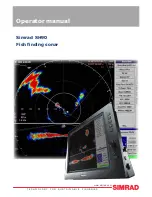
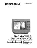
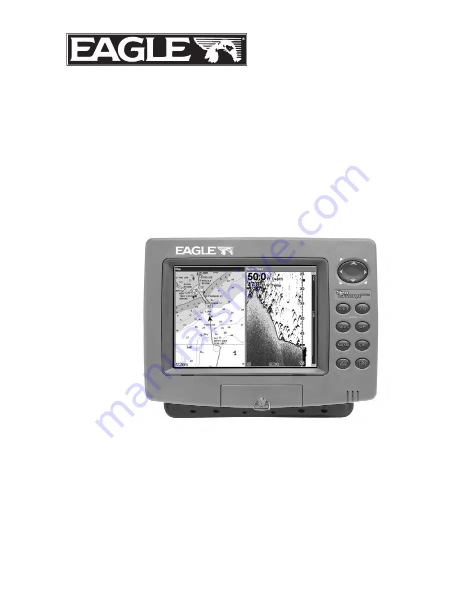
Page 199: ...ry to send a product for repair or replacement you must first receive a return authorization number from Customer Service Products shipped without a return authorization will not be accepted When shipping we recommend you do the following 1 Please do not ship the knobs or mounting bracket with your unit 2 If you are sending a check for repair please place your check in an envelope and tape it to t...

Page 200: ...Visit our web site www eaglesonar com Eagle Pub 988 0143 811 Copyright 2005 All Rights Reserved Printed in USA 031405 LEI Eagle ...

Reviews: