background image

INSTALLATION AND

OPERATION INSTRUCTIONS

Map Guide Pro

TM

Summary of Contents for Map Guide Pro

Page 1: ...INSTALLATION AND OPERATION INSTRUCTIONS Map Guide Pro TM ...

Page 2: ...ge of all available navigation tools when trav elling to a waypoint but will also visually check to make certain a clear safe path to the waypoint is always available The operating and storage temperature for your unit is from 4 degrees to 167 degrees Fahrenheit 20 to 75 degrees Celsius Extended storage temperatures higher or lower than specified will cause the liquid crystal display to fail Neith...

Page 3: ...ce to radio com munications However there is no guarantee that interference will not oc cur in a particular installation If this equipment does cause harmful inter ference to radio or television reception which can be determined by turn ing the equipment off and on the user is encouraged to try to correct the interference by one or more of the following measures Reorient or relocate the receiving ...

Page 4: ...tation 12 Autozoom 14 View Destination 15 Range Rings Grid Lines 15 Earth Map Options 16 Earth Map On Off 16 Text Labels 16 Locations 16 Map Detail 16 Gray Fill 17 Plot Trail Options 18 Clear Trail 18 Flash Trail 18 Update Options 18 Save Trail 18 Show Trail 19 ICONS 19 Place Icon Present Position 19 Place Icon Cursor Position 20 Icon Options 20 MAP DOWNLOADING 21 WINDOWS 23 Reprogram Boxes 28 RES...

Page 5: ...7 Add From Map 38 Delete a Waypoint 38 Waypoint Statistics 39 Following a Route 39 Waypoint Information 40 Delete a Route 40 CANCEL NAVIGATION 40 Navigation Notes 40 SYSTEM SETUP 42 Sound 42 Contrast 42 Set Local Time 42 Units of Measure 43 NMEA DGPS 43 NMEA Output 44 Configure NMEA Output 44 DGPS 44 Serial Communication Setup 46 Reset Options 46 Reset Groups 47 System Info 47 GPS SETUP 47 Power S...

Page 6: ...ltitude called a 3D fix Remember the unit must have a clear view of the satellites in order to receive their signals Unlike radio or television GPS works at very high frequencies The signals can be blocked easily by trees buildings even your body Fortunately they do travel through glass and plastic so your receiver will work in the car if it has a clear view of the satellites through the windshiel...

Page 7: ...mitters and gives them to the GPS receiver which then uses them to show a more accurate position The ironic part is the federal government implemented SA and is also operating many DGPS transmitters You can use the signals from all of the Coast Guard DGPS stations for free by the way The downside to this is it requires another piece of electronic gear the DGPS receiver which usually isn t small en...

Page 8: ...of bat teries For example don t use both alka line and ni cad batteries at the same time Battery Installation First turn the unit so that its back is facing you Push the two tabs to the left and re move the battery cover as shown at right Install the batteries according to this dia gram There s a decal in the battery com partment showing the correct polarity also Replace the battery compartment co...

Page 9: ...zoom in or zoom out the view on the plotter screen The ENT and EXIT keys are used to enter or clear data or screens Save and edit waypoints using the WPT key The PWR key turns the unit on and off Pressing it once while the unit is operating turns on the screen s backlight To prevent an acci dental shutdown you must hold the PWR key down for a few seconds in order to turn the unit off Menus Most of...

Page 10: ...asn t locked onto that satellite and it isn t being used to solve the position Beneath the circular graph are the bar graphs one for each satellite in view Although the unit has twelve channels it dedicates one channel per visible satellite Therefore if only six satellites are visible only six bar charts show at the bottom of the screen The higher the bar on the graph the better the unit is receiv...

Page 11: ...tes When your GPS receiver is turned on for the first time it doesn t know what your position or elevation altitude is It does know the current UTC time and date since these were programmed into it at the factory and an internal clock keeps the time while the unit is turned off It begins searching for the satellites using the above data that it ac quired the last time it was turned on This probabl...

Page 12: ...eds to determine which satellites are in view Once the satellites are known the receiver searches for only those satellites making a lock faster than an auto search method Position Acquisition When the receiver locks onto the satellites and calculates a position it shows the message Position Acquired on the screen All position and navigation data flashes until the unit acquires a position Do not r...

Page 13: ...e EXIT key to erase the menu Navigation Screens There are two different navigation screens Nav screen number one shows a graphical view of your trip Nav screen number 2 shows all navigation details in large digital numbers You can also customize both navigation screens to show data other than the default See the Programming Boxes section for more information Nav Screen 1 This screen has a compass ...

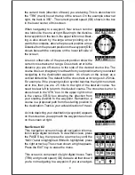
Page 14: ...cal dotted line The default for the cross track error range is 0 25 mile For example if the present position symbol touches the right cross track error line then you are 25 mile to the right of the desired course You need to steer left to return to the desired course The cross track error is also shown in the XTK box In the upper right corner is the course CRS box showing the direction from your s...

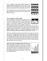
Page 15: ...o get back on course This is called chasing the needle If you steer towards the line needle you ll always be heading in the correct direction to get back on course The CDI s range shows beneath the CDI label On the above screen the CDI range is 20 mile which is the default You can adjust the range by selecting the ALARMS CDI label on the main menu This is also shown by the dotted lines at the far ...

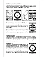
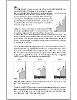
Page 16: ...ow is your plot trail or path you ve taken The plotter s range shows in the lower left corner of the screen In this example the plotter s range is two miles from the left edge of the screen to the right There are three different mapping screens To view the other map screens press the PAGES key highlight the MAP label and press the right arrow key until the desired map screen appears Press the EXIT...

Page 17: ... highlighted Press the right arrow key A screen similar to the one at right appears Change Maps Changes made to the map using the options in the Map Setup is normally made to all map screens The change can be limited to the map screen currently in use however by switching the All Maps to This Map in the Change menu To do this simply highlight the Change label then press the right arrow key To swit...

Page 18: ...iew the present position moves straight towards the top of the display A N shows to help you see which direction is north when the track up mode is on Remember in the track up mode the screen ro tates as you change direction It always keeps your direction of travel track heading towards the top of the screen In the course up mode the screen is locked into your original bearing to the recalled wayp...

Page 19: ...autozoom mode on the unit zooms out until the entire course shows from the present position to the destination waypoint recalled waypoint As you travel towards the destination the unit automatically begins zoom ing in one zoom range at a time keeping the destination on the screen The screens below show a slice of the progression of a trip near a lake Screen number one is the start and is on the 6 ...

Page 20: ...the MENU key select Map 1 Setup then Map Options Highlight View Dest then press the right arrow key to turn it on Press the EXIT key repeatedly to erase the menus VIEW DESTINATION OFF VIEW DESTINATION ON Range Rings Grid Lines The map screen can be customized with rings that are 1 4 of the range and or grids that divide the plotter into equal segments of latitude and longitude To do this press the...

Page 21: ...the map such as Lake Tahoe or Mississippi River off or on The default is on Press the left arrow key to turn them off Locations Normally text disappears as you zoom out This declutters the screen making it easier to see signifi cant map detail Turning Locations on from the earth map menu places a dot on the screen where a text label should be when the screen is zoomed out The arrows on the screen ...

Page 22: ...p menu then press the right arrow key Gray Fill When this unit is first turned on all water lakes oceans rivers is filled with gray to distinguish it from land which is clear See below To make the land fill with gray and water remain clear select the Gray Fill label from the Earth Map menu then press the left arrow key Press the EXIT key repeatedly to return to the mapping screen WATER FILLED WITH...

Page 23: ...ces a dot on the screen every 3 seconds to create the plot trail You can change this time from once per second to once every thirty min utes The plot trail can also be updated by distance instead of by time The distance update rate can be set from 0 01 to once every 10 miles From the trail options menu choose UPDATE BY to change the update rate or type To change the rate or distance simply select ...

Page 24: ...n be placed any where on the screen They can be used to mark fishing or hunting loca tions landmarks boat ramps and virtually any point of interest An icon can be placed at your present position or at the cursor s location Place Icon Present Position To place an icon at your present position simply press the ENT key while the mapping screen is on The screen shown at right appears Use the arrow key...

Page 25: ...ns that have been placed on all map screens To erase only a certain type of icon select the DEL ICON TYPE menu The icon menu appears Highlight the icon style that you want to erase from memory then press the ENT key The unit returns to the map screen with only the selected icons erased MOVE CURSOR PRESS ENT KEY SELECT ICON PRESS ENT KEY ICON PLACED AT CURSOR POS Place Icon Cursor Position To place...

Page 26: ...personal computer BACKGROUND MAP ONLY BACKGROUND MAP WITH IMS MAP Currently the MapSelect CD has the following databases IMS SmartMap data covers the 48 contiguous states and are broken down into 64 different mapping regions Contained in this database are the names and locations of over 140 000 cities 30 000 national state and county parks 120 000 inland bodies of water plus coastal waters out to ...

Page 27: ...then Initialize This starts the communication between the GPS unit and the computer If the communications fail try switching the baud rate on the Map Guide Pro to a lower setting Once the communications are established click on the Map Select tab Choose a memory partition to download a map into then choose a map If you have problems click on Help There is extensive help available on the GDM 16 pro...

Page 28: ...p appears press the EXIT key to erase the Pages menu A summary of the groups follows Note that many of the groups have navigation data that re quire navigation to a waypoint in order to show data See the waypoint section for information on setting up the unit for waypoint navigation Group A This screen has two maps one above the other Each map works sepa rately from the other For example the top m...

Page 29: ... at the top The CDI shows in the middle of the screen Your present course CRS shows at the top of the CDI Track TRK and distance to go DIS show at the bot tom of the screen Group D This screen is the same as group C except ground speed GS replaces distance to go DIS in the lower right corner Group E A CDI combined with digital boxes makes up this screen Beneath the CDI are bearing BRG distance to ...

Page 30: ...e by GPS receiver and corrections are available OLD Unit hasn t received corrections in last 60 seconds NA No correction available The DGPS station s ID number frequency bit rate signal strength signal to noise ratio SNR and time since the GPS receiver received the satel lite corrections AGE all show at the bottom of this screen Group H This is a time screen An analog clock shows at the top follow...

Page 31: ...ing in the clock s window CLOCK ALARM MENU CLOCK ALARM ADJUST MENU CLOCK ALARM SET Group I This group has estimated time enroute ETE at the top of the screen a trip timer estimated time of arrival ETA and the digital clock The trip timer measures the total time you have been travelling It starts counting when you exceed a preset speed The default is 5 miles per hour You can adjust this time from z...

Page 32: ...ne above center appears To start the timer simply high light the UP TIMER menu then press the right arrow key To reset the timer to zero select the UP TIMER RESET menu The up timer has an alarm that can be set to sound at a preset time For example one hour from now three hours etc To set the alarm highlight the UP TIMER ALM SET and press the right arrow key The screen at the upper right appears Us...

Page 33: ... to the screen that you want to customize Map 2 shown at right is used in this example Next press the MENU key then select the Reprogram Boxes menu The screen shown be low left appears This is the MAP 2 edit screen The BRG box near the left corner flashes which means it s ready for change If you don t want to change this box simply press the left or right arrow key to move to the box that you do w...

Page 34: ...aypoint and the unit will show distance and bearing from your present position to the car This unit stores up to 750 waypoints Waypoint Menu With few exceptions in order to save modify or recall a waypoint you ll use the waypoint menu shown at right The current waypoint number shows at the top of the screen Its name appears beneath the GO TO WPT label The waypoint s position distance and bear ing ...

Page 35: ...nt number You can pick the waypoint num ber then save your present or cursor position To save your present position press the WPT key once If you re saving the cursor position first move the cursor to the desired location then press the WPT key A screen similar to the one at right appears Highlight the WPT label at the top of the screen Press the right or left arrow keys until the desired waypoint...

Page 36: ...tel lites being tracked and their location relative to your position and so on However even with SA turned on this GPS receiver can show surpris ingly accurate position information If you wish to increase the accuracy of a saved position use the waypoint averaging method This method requires the unit to remain untouched at the location that you want to save preferably for at least one hour Longer ...

Page 37: ...Project WPT menu and press the right arrow key The screen at right appears Select a waypoint using either the waypoint number or way point list When you ve chosen the waypoint highlight the SET REFERENCE label and press the right ar row key The unit returns to the Project WPT screen shown above The starting waypoint you chose shows in the middle of this screen Now set the distance from the startin...

Page 38: ... press the right arrow key to select it The waypoint menu reappears Note When created a waypoint is given a default name designated by an asterisk Default names are not shown on the map The waypoint number is shown until it s renamed EDITING A WAYPOINT You can customize a waypoint by giving it a name or change it s position or icon To do this first press the WPT key The waypoint screen appears Fol...

Page 39: ...sign to the waypoint then press the ENT key The waypoint now has the new icon WAYPOINT NAVIGATION The Map Guide Pro makes it easy to navigate to any waypoint All you have to do is select the waypoint see page 31 then highlight the GOTO WPT label on the waypoint screen and press the right arrow key The unit immediately shows navigation information to the waypoint on all navi gation map and windows ...

Page 40: ... this page is the cursor destination when the cursor position is used as a destination If you follow the course line you ll reach the destination covering the shortest distance in the least time CAUTION This product does NOT take land features restricted or prohibited areas or any other feature into account when it projects the course line on the screen Use caution when navigating to a location Ma...

Page 41: ...o erase all of the information in a waypoint first press the WPT key then select the waypoint you want to erase Now highlight the DELETE WPT label and press the right arrow key A message ap pears asking if you really want to delete this waypoint Press the right arrow key to delete it the left to exit without deleting the waypoint Delete All Waypoints You can remove all of the waypoints from the un...

Page 42: ...oxes in the lower half of the screen com prise the list of waypoints that form the route To add waypoints to the route highlight the first gray box in the middle of the screen and press the right arrow key The screen shown at right appears To add a waypoint to the route from the waypoint table select the ADDWPT label The screen shown at the top left on the next page appears Add From Waypoint List ...

Page 43: ...e move the cursor to that location and press the ENT key When you re finished press the EXIT key The screen below right appears SELECT FIRST WAYPOINT AND ADD TO ROUTE UNIT RETURNS TO ROUTE PAGE REPEAT UNTIL ALL WAYPOINTS ARE IN ROUTE The total route distance shows at the bottom of the screen Continue selecting waypoints until all of the waypoints in the route are on the list Press the EXIT key to ...

Page 44: ...waypoint to your position then travel forward or reverse through the route using the AUTO START feature To follow a route first select the route number that you wish to follow by highlighting the Route label and pressing the left or right arrow keys until the desired route number appears In this example we re using route number one To run the route from the last way point to the first highlight th...

Page 45: ...s navigation along the leg of the route that is closest to your present position The screen shown below left shows the result of the auto start feature When the route was started the first leg of the route from waypoint 4 to waypoint 2 was the closest to the present position Therefore the unit shows navigation information to waypoint number 2 The first leg of the route from 4 to 2 is shown on the ...

Page 46: ...ase them or the left arrow key to leave the way points in memory The unit returns to the routes menu Press the EXIT key to erase the menu CANCEL NAVIGATION This unit continues to navigate to a recalled waypoint the last waypoint in a route or the cursor position until you stop it To stop the navigation function press the MENU key then press the up or down arrow keys until the Cancel Nav label is h...

Page 47: ...dicator on the satellite status screen shows when the lights are on The default light level is maximum To reduce the level select BACK LIGHT then press the left arrow key until the lights are at the desired level To increase the light level press the right arrow key The lights automatically turn off after 30 seconds to preserve the battery power It will do this even if the external power is applie...

Page 48: ...ats To change a unit of measure first select CHANGE UNITS from the System Setup menu High light the desired selection then press the left or right arrow key You can change any or all of the settings on this page When you re finished press the EXIT key NMEA DGPS This product transmits data through the power data port in the back of the unit using NMEA 0183 format version 1 5 or 2 0 The data is used...

Page 49: ...shown below appears NMEA 0183 Version There are two versions of the NMEA data 1 5 and 2 0 If your other equipment requires 1 5 press the left ar row key to select it GLL RMC RMB APB GGA GSA GSV Sentences Some equipment requires different sentence The de fault setting for these sentences is on In other words it automatically sends these sentences when NMEA is turned on To turn any of these off move...

Page 50: ... PRO WIRES OTHER DEVICE S WIRES MAP GUIDE PRO TRANSMITTING NMEA DATA TO ANOTHER DEVICE TO MAP GUIDE PRO DGPS RECEIVER 12 VDC BATTERY BLACK WIRE GROUND WIRES WHITE WIRE RED WIRE TO 12V DGPS RECEIVER S RECEIVE DATA WIRE IF NEEDED MAP GUIDE PRO WIRES MAP GUIDE PRO RECEIVING DATA FROM A DGPS RECEIVER GREEN WIRE DGPS RECEIVER S TRANSMIT DATA WIRE ...

Page 51: ... other serial device to this unit including DGPS receivers you ll probably need to change the communications settings To do this select COM PORT SETUP on the System Setup menu Press the right arrow key The screen shown at right appears Check your computer or DGPS receiver s manual for the proper data settings Highlight the menu item you need to change Press the left or right arrow keys to change t...

Page 52: ...t appears POWER SAVE This GPS receiver has an important power save fea ture that significantly improves battery life However this feature does affect the receiver s performance If you are using it under heavy cover such as trees or around tall buildings the receiver can lose its lock on the satellites easier when the power save feature is enabled The power save feature changes the position update ...

Page 53: ...rnate MGRS on the Map Guide Pro Your position and datum in use determines which one to use If you use the standard and your position is off significantly then try using the alternate Note When the position format is changed it affects the way all positions are shown on all screens This includes waypoints To change the format highlight the Position Format label on the GPS Setup menu then press the ...

Page 54: ... at all times Remember the position error on any radio navigation system is very dy namic and the PCF offset should never be used in an attempt to cancel the error In general terms PCF should only be used if your map indicates what the possible error is PCF should always be reset to zero when you re finished with the chart For example suppose you are stopped at a location that is accurately marked...

Page 55: ... is due in large part to SA or selective availability SA is small inaccuracies purposefully put into the GPS satellite s signal by the government This cause wide variations in the track display and other navigation displays when using the unit at slow speeds If you re using this receiver without DGPS and stop the position pinning feature locks the present position indicator on the plotter until yo...

Page 56: ...wn at right appears Press the up or down arrow key to move the black box to the desired alarm then press the right arrow key to turn it on To adjust an alarm s distance move the black box to the alarm s DIS menu item then press the right or left arrow keys to increase or decrease the alarm s dis tance When you re finished press the EXIT key to erase this menu Important Alarm Notes Anchor Alarm Sin...

Page 57: ...tor is used for this example The sunrise and sunset for today s date appear in the cen ter of the screen Today s date shows at the top of the screen If you want to know the sunrise sunset for a different date press the ENT key then enter the new date with the arrow keys The unit returns to the sun rise sunset calculator screen with the sunrise and sun set times shown for the date you entered The s...

Page 58: ...ition If you want to change the starting position highlight the SET START WPT label on the Simulator Setup menu then press the right arrow key The screen shown at right appears You can select any waypoint as the simulator s starting point Select the starting point by pressing the right ar row key on the WPT label until the desired starting waypoint number appears Now highlight the SET SIM START la...

Page 59: ...ack The direction you re travelling DIS Distance Distance remaining between your present po sition and a waypoint DNT UPT Countdown timer DNT and Count up timer UPT ETA Estimated Time of Arrival ETE Estimated Time En route ICON A symbol you can place on the map representing a land mark POSITION Your present position GS Ground Speed Your actual speed UTC Coordinated Universal Time Time at the prime...

Page 60: ...ARC 1960 MEAN ASCENSION ISLAND 1958 ASTRO BEACON E 1945 IWO JIMA ASTRO DOS 714 ST HELENA ISLAND ASTRO TERN ISLAND 1961 ASTRONOMICAL STATION 52 MARCUS ISLE AUSTRALIAN GEODETIC 1966 AUSTRALIAN GEODETIC 1984 AYABELLE LIGHTHOUSE DJIBOUTI BELLEVUE IGN EFATE ERRAOMANGO BERMUDA 1957 BISSAU GUINEA BOGOTA OBSERVATORY COLOMBIA BUKIT RIMPAH INDONESIA CAMP AREA ASTRO ANTARCTICA CAMPO INCHAUSPE ARGENTINA CANTO...

Page 61: ...ean 1950 England Channel Islands Ireland Scotland Shetland Islands European 1950 Finland Norway European 1950 Greece European 1950 Iran EUROPEAN 1950 ITALY SARDINIA EUROPEAN 1950 ITALY SICILY EUROPEAN 1950 MALTA EUROPEAN 1950 SPAIN PORTUGAL EUROPEAN 1979 MEAN FORT THOMAS 1955 NEVIS ST KITTS GAN 1970 REPUBLIC OF MALDIVES GEODETIC DATUM 1949 NEW ZEALAND GRACIOSA BASE SW 1948 AZORES GUAM 1963 GUNUNG ...

Page 62: ...A 1927 MEAN CARRIBEAN N AMERICA 1927 MEAN CENTRAL AMER N AMERICA 1927 MEAN CANADA N AMERICA 1927 MEAN CONUS N AMERICA 1927 MEAN CONUS EAST N AMERICA 1927 MEAN CONUS WEST N AMERICA 1927 ALASKA N AMERICA 1927 BAHAMAS NO SAN SALV N AMERICA 1927 BAHAMAS N AMERICAN 1927 CANADA WEST N AMERICAN 1927 CANADA CENTRAL N AMERICAN 1927 CANADA EAST N AMERICAN 1927 CANADA NORTH N AMERICAN 1927 CANADA YUKON Nahrw...

Page 63: ...n 1927 Mexico North American 1983 Alaska Canada CONUS North American 1983 Central America Mexico Observaorio Metereo 1939 Azores Corvo Flores Islands Old Egyptian 1907 Egypt Old Hawaiian Mean for Hawaii Kauai Maui Oahu Old Hawaiian Hawaii Old Hawaiian Kauai Old Hawaiian Maui Old Hawaiian Oahu Oman Oman Ordinance Survey Great Britain 1936 Mean for England Isle of Man Scotland Shetland Islands Wales...

Page 64: ...th American 1969 Argentina South American 1969 Bolivia South American 1969 Brazil South American 1969 Chile South American 1969 Colombia South American 1969 Ecuador South American 1969 Ecuador Baltra Galapagos South American 1969 Guyana South American 1969 Paraguay South American 1969 Peru South American 1969 Trinidad Tobago South American 1969 Venezuela SOUTH ASIA SINGAPORE TANANARIVE OBSERVATORY...

Page 65: ...rief note detailing the problem you re having with the unit Please include your name address and daytime telephone number 4 Please include payment for non warranty repairs Check money order Visa or MasterCard may be used 5 Fill in your name address zip code date and RA number in the blanks provided on the UPS form included with your unit 6 Attach the label to the shipping box tear off the tab for ...

Page 66: ...Most quality dealers that handle marine elec tronic equipment should be able to assist you with these items Consult your local telephone directory for listings 2 LEI Extras Inc P O Box 129 Catoosa OK 74015 0129 or call 800 324 0045 USA orders only Eagle Electronics may find it necessary to change or end our shipping policies regulations and special offers at any time We reserve the right to do so ...

Page 67: ...NCTION OR NON CON FORMITY CONCERNING THE PRODUCT OR FOR ANY LOSS OR DAMAGE RESULT ING FROM ANY OTHER CAUSE WHATSOEVER WE WILL NOT UNDER ANY CIR CUMSTANCES BE LIABLE TO ANYONE FOR ANY SPECIAL CONSEQUENTIAL INCI DENTAL OR OTHER INDIRECT DAMAGE OF ANY KIND Some states do not allow the exclusion or limitation of incidental or consequential dam ages so the above limitations or exclusions may not apply ...

Page 68: ...the nonexclusive nonassignable right to use these Databases for supplemental navigation reference purposes but only as long as you comply with the terms and conditions of this License Agreement We reserve the right to terminate this license if you violate any aspect of this License Agreement You are responsible for using official government charts and prudent navigation for safe travel 3 The Datab...

Page 69: ...TANCES BE LIABLE TO ANYONE FOR ANY SPECIAL CONSEQUENTIAL INCIDENTAL OR OTHER INDIRECT DAMAGE OF ANY KIND Some states do not allow the exclusion or limitation of incidental or consequential dam ages so the above limitations or exclusions may not apply to you This warranty does NOT apply in the following circumstances 1 when the product has been serviced or repaired by anyone other than us 2 when th...

Page 70: ...brief note with the product describing the problem Be sure to include your name return shipping address and a daytime telephone number How to Obtain Service International Customers Only Except Canada If you need service or repairs contact the dealer in the country you purchased your unit WARRANTY REPAIR WILL BE HONORED ONLY IN THE COUNTRY UNIT WAS PURCHASED Please follow the shipping instructions ...

Page 71: ... See page 62 inside this manual for complete warranty details If your unit fails and the failure is not covered by the original warranty Eagle has a flat rate repair policy that covers your unit and accessories packed with the unit at the factory There is a 180 day warranty on all non warranty repairs from the factory which is similar to the original warranty but is for 180 days rather than one ye...

Reviews: