background image

MANUAL IRONWORKER

INSTRUCTIONS

Item #21566

Summary of Contents for 21566

Page 1: ...MANUAL IRONWORKER INSTRUCTIONS Item 21566 ...

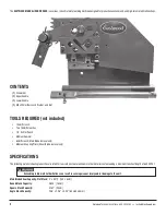
Page 2: ...s Shear Blade removal only SPECIFICATIONS The following material shearing capacities are rated for low carbon steel aluminum or other materials not exceeding a maximum tensile strength of 64 000 PSI Main Blade Shear Capacity Flat Stock 4 x 0 312 100 x 8mm Round Stock Capacity 0 625 16mm Square Stock Capacity 0 787 20mm Angle Stock Capacity 2 36 x 2 36 x 0 25 60 x 60 x 6mm Exceeding rated material ...

Page 3: ...n a clean uncluttered environment Be sure there is sufficient working room around the tool to allow for safe handling of various sizes of metal The Eastwood Manual Ironworker was specifically designed to be operated by one person only Never have one person operate the Handle while another feeds the workpiece or serious injury could occur Excessive resistance while operating could indicate a defect...

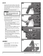
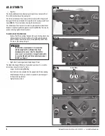
Page 4: ... and over center to relieve tension of the Handle Return Springs FIG 4 Pull off the two Handle Return Springs FIG 5 and set aside for reinstallation noting which one is Left and which is Right Keep the Actuating Arm in the upward over center position FIG 6 Replace the Handle Return Springs making sure the hooked fingers are positioned properly just ahead of the Drive Posts with the open loops faci...

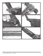
Page 5: ...To order parts and supplies 800 343 9353 eastwood com 5 FIG 5 FIG 6 FIG 7 FIG 8 FIG 9 FIG 10 ...

Page 6: ...move Pivot Pin by griping the head firmly and rotating side to side while pulling firmly Carefully withdraw Pivot Pin and immediately place it through the alternate pivot position FIG 12 Rotate Pivot Pin side to side while pushing in Right Side Round Square and Angle Support Plate The Right Side Support Plate may be adjusted up or down to accommo date various sizes of material To Do So Loosen the ...

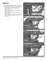
Page 7: ...intended for most com mon shearing operations of flat stock and sheet metal up to 4 x 0 312 100 x 8mm Round Shear FIG 17 The Round Shear is for round bar stock up to 0 625 16mm in diameter Square Shear FIG 17 The Square Shear is for square bar stock up to 0 787 20mm Angle T Shear FIG 18 The Angle T Shear is designed to accept most angle and T profile stock up to 2 36 x 2 36 x 0 25 60 x 60 x 6mm FI...

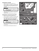
Page 8: ...eve cut piece from unit SHEARING OPERATION ROUND SQUARE AND ANGLE SHEARS Measure and mark a cut line on the material to be cut Raise the Actuating Arm to the highest position opening the blades Insert the material to be cut into the left side of the unit at the proper configured opening and through the blades allowing the right side Support Plate to support the material FIG 20 Rotate the Actuating...

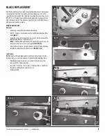
Page 9: ...Outer Blade Retaining Plate bolts FIG 21 Using the same 18mm wrenches remove the 2 bolts securing the Main Moving Blade to the Blade Frame NOTE The Main Moving Blade has 2 finished surfaces and may be reversed if one side is worn or damaged FIGS 22 23 With an 18mm wrench remove the bolts on the left side attaching the Main Fixed Blade to the Main Frame FIGS 24 25 Installation NOTE The Main Moving ...

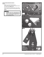
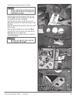
Page 10: ... the right side of the unit with an 18mm wrench FIGS 26 27 Remove the Pivot Pin then pull the Actuating Arm stub all the way up and over center to relieve tension of the Handle Return Springs FIG 28 The following steps involve components and assem blies that are heavy and will suddenly fall away Use extreme care and hold these components securely when withdrawing fasteners FIG 26 FIG 27 FIG 28 ...

Page 11: ...mbly using an 18mm wrench and 10mm hex key Remove the Moving Shear Blade with an 18mm wrench FIG 31 The V Upper Blade can now be removed from the back side of the Moving Shear Blade using a 16mm wrench The Fixed Blades are now fully exposed and may be removed with a 16mm wrench FIG 32 Take note of the position of the Actuating Lever Sec tor Gear position and relation to the teeth with those of the...

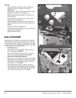
Page 12: ...ion and maintain an even relationship across their entire surface As the East wood Manual Iron Worker is constructed to a high degree of precision and accuracy virtually no adjustment is required when replacing blades Below are several reference points for proper operation Main Blade Alignment The Main Blades should be overlapping at the inboard end by ap prox 1 25mm when open FIG 34 At the open e...

Page 13: ...e Zerk Fittings located at the top of the Moving Shear Blade Apply a good quality automotive chassis grease to the mating gear teeth Keep all areas of the tool clean particularly those surfaces that contact metal workpieces Dirt and metal chips can cause uneven shearing and blade damage Store in a clean dry environment when not in use Coat all machined surfaces with a light lubricant film of oil o...

Page 14: ...NOTES 14 Eastwood Technical Assistance 800 343 9353 techelp eastwood com ...

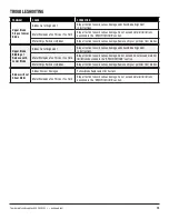
Page 15: ...pper Blade Binding at Release with Lower Blade Blades Out of Alignment Stop all action to avoid serious damage and check Blade Alignment in instructions Metal Workpiece Too Thick or Too Hard Stop all action to avoid serious damage Do not exceed Do not exceed material limitations described in the SPECIFICATIONS section Metal Chips Particles in Blades Stop all action to avoid serious damage Remove c...

Page 16: ...Bead Roller Kit 21489 Shrinker Stretcher Set 21491 Shrinker Stretcher Stand Copyright 2018 Easthill Group Inc 7 18 Instruction item 21566Q Rev 1 If you have any questions about the use of this product please contact The Eastwood Technical Assistance Service Department 800 343 9353 email techelp eastwood com PDF version of this manual is available at eastwood com The Eastwood Company 263 Shoemaker ...

Reviews: