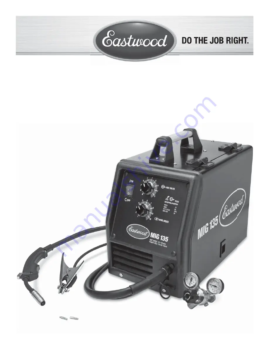
background image

MIG 135  WELDER

ASSEMBLY & OPERATING INSTRUCTIONS

Part #12011

Summary of Contents for MIG 135

Page 1: ...MIG135 WELDER ASSEMBLY OPERATING INSTRUCTIONS Part 12011...

Page 2: ...this warranty plan Eastwood will determine whether repair or replacement is the most suitable option to rectify the defect At Eastwood s request the purchaser must return to Eastwood any products clai...

Page 3: ...is to be in the OFF 0 position when installing the work cable and gun and while plugging in the power cord 2 Always wear dry protective clothing and leather welding gloves and insulated footwear 3 Alw...

Page 4: ...any welding operations Always wear long pants long sleeved shirts and leather welding gloves Make sure that all persons in the welding area are protected from heat sparks and ultraviolet rays Use addi...

Page 5: ...rol 6 Latch 7 Power Cord 8 Breaker Reset Switch 9 Shielding Gas Inlet 10 Rocker Arm 11 Pressure Adjuster 12 Guide Pipe 13 MIG Gun Thumb Screw 14 Positive Terminal 15 Negative Terminal 7 9 21 13 10 8 1...

Page 6: ...ic wire loom Fig 1B and up to the 2 connectors above the drive motor Fig 2B The 2 leads can be connected to either of the two connections as the polarity does not matter INSTALLING THE GROUND CLAMP 1...

Page 7: ...e 4 Insert the large brass male fitting on the Shielding Gas Regulator into the female fitting on the Shielding Gas Bottle NOTE Do not use White Teflon Tape on this connection as it is a tapered threa...

Page 8: ...d onto the spindle and reinstall the spacer and the wing nut 4 To set the tension on the wire tighten the wing nut till there is a slight resistance to spinning the wire spool on the spindle If the te...

Page 9: ...ller on the drive motor has 2 grooves one for 0 023 0 6mm welding wire and another for 0 030 0 8mm or 0 035 0 9mm welding wire Your MIG135 comes with the drive roller installed for using 0 023 0 6mm w...

Page 10: ...ire feed which starts the arc NOTE A push perpendicular or drag technique can be used to weld the pieces together the type used depends on the type of joint as well as other influential conditions 11...

Page 11: ...re the edges are being joined 5 Tee Weld is a joint between two pieces where one is perpendicular to the other Weld is a joint between two pieces where 2 Corner Weld is a joint between two pieces that...

Page 12: ...described below 1 Clean the metal to be welded of any paint rust oil grease dirt or any other contaminants that may be on the surface of the piece 2 Secure the pieces to be welded in place using clamp...

Page 13: ...Duty Cycle being a percentage of that 10 Minutes If welding at 90 Amps with a 20 Duty Cycle within a 10 Minute block of time you can weld for 2 Minutes with 8 Minutes of cooling for the welder If the...

Page 14: ...14 Eastwood Technical Assistance 800 544 5118 techelp eastwood com TROUBLESHOOTING...

Page 15: ...To order parts and supplies 800 345 1178 eastwood com 15 NOTES...

Page 16: ...ck 12224 0 030 0 8mm Contact Tips 5 Pack 12210 Nozzle 12226 0 023 Solid MIG Wire 2lbs 4in Spool 12227 0 030 Solid MIG Wire 2lbs 4in Spool 12225 0 030 Flux Cored Wire 2lbs 4in Spool OPTIONAL PARTS 1379...

Reviews: