background image


PM10U 


EBARA 

CORPORATION 


EV-A Series 

DRY VACUUM PUMP 


APPLICABLE TYPE 

EV-A06 


INSTRUCTION MANUAL 


Summary of Contents for EV-A Series

Page 1: ...PM10U EBARA CORPORATION EV A Series DRY VACUUM PUMP APPLICABLE TYPE EV A06 INSTRUCTION MANUAL ...

Page 2: ......

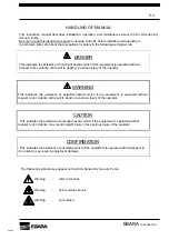
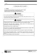
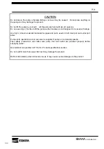
Page 3: ...ous injury of the operator WARNING This indicates the existence of potential hazard which if the equipment is operated without respect to its contents will result in death or a serious injury of the operator CAUTION This indicates the existence of potential hazard which if the equipment is operated without respect to its contents may result in slight injury or less serious injury of the operator C...

Page 4: ...c Condensable gas Water vapor or mixed gas with solvent Clean gas exhaust Inert gas such as nitrogen atmosphere exhaust dry types of gas These are one of the examples Regardless of the solvent kind and its amount contact one of our sales offices before you start operation When you pump flammable chemical including solvent stated above always introduce N2 through gas ballast system To vacuum solven...

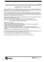
Page 5: ...such as dry air and inert gases N2 etc One 1 year warranty Pumping condensable gases such as water vapor and solvent mixed gas Prior meeting is required when pumping solvent Exemption of the warranty Failure due to improper handling operation or storage Failure caused by the usage of special gas like acid alkaline corrosive gas or the usage possibly contains solid or may cause solidification and c...

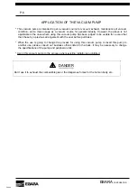
Page 6: ... to be usable for a use other than these by a previous arrangement with the user before purchase When the use is going to change the process for using this vacuum pump or divert this pump to another use please consult our business offices listed in the back It may be necessary to change the specifications of the pump and peripheral units Using this vacuum pump to the process where existing radiati...

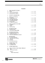
Page 7: ...stallation 20 4 2 Piping 23 4 3 Electric Wiring 24 5 OPERATION PANEL 5 1 Operation Panel 29 5 2 How to Switch LED Display 31 6 OPERATION AND STOP 6 1 Preparations for Operation 33 6 2 Operation and Stop 33 6 3 About the Gas Ballast Mechanism 37 7 MAINTENANCE 7 1 Routine Maintenance 39 7 2 Inlet and Outlet Plumbing 40 7 3 Lubricant 40 7 4 Overhaul 42 7 5 Removal of the Pump 43 8 TROUBLESHOOTING 8 1...

Page 8: ...nge them so that they may not come in contact with the human body and combustible materials Perform leak check after piping maintenance Apply pressure form exhaust piping and pressurize up to 0 05 MPa for pressure leak check Wiring work must be done by qualified workers This product is not equipped with earth leakage breaker ELB and emergency off switch EMO Follow the local regulations when instal...

Page 9: ...d with slings Use high corrosion resistant materials for pipes and parts used on both inlet port and outlet port sides Pump starts operation as soon as power is supplied if pump run command presents Take safety precautions and make sure pump inlet and outlet are plumbed properly before supplying power Use lubricant oil specified on P 18 3 4 Product specification section Do not overfill more than u...

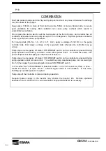
Page 10: ... the controller may go wrong Pump stops in emergency off state if STOP RESET switch on the controller is pressed during pump operation with driving connector under direct power input To restart the pump turn power off wait until LED light goes off then turn it back on Pump stops in emergency off state if STOP RESET switch on the controller is pressed during pump operation under remote control To r...

Page 11: ...the pump stop When the pump stops and the gas ballast valve still remains open state air is introduced from the gas ballast valve into the pump This cannot keep vacuum condition of the pump If it is necessary to keep vacuum of the pump and or equipment attach shut off valve at the top of the pump inlet to hold vacuum condition and shut it off before the pump is stopped When condensable gas such as...

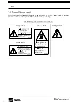
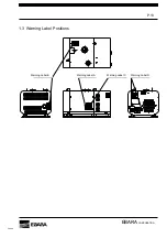
Page 12: ...the main body of the dry vacuum pump to provoke cautions on use The warning label positions are shown on the next page List of Warning Labels on the Dry Vacuum Pump Warning Label A Warning Label B Warning Label D Warning Label C Hot surface Can burn hands Do not touch 警 告 WARNING 高温の為 火傷の恐れあり 触れないでください ...

Page 13: ... PM10U EBARA CORPORATION 1 3 Warning Label Positions Warning Label C Warning Label A Warning Label D 1Ph AC100 120V 50 60Hz PE Warning Label B Warning Label B Warning Label A Warning Label C Warning Label D ...

Page 14: ...lt is found please inform one of our offices listed in the back at once Regarding pump accessories check them according to the packing list separately dispatched Storage of the Pump In case the pump is not installed immediately after it is received store it in a clean environment in the following conditions Temperature 5 to 40 deg C Humidity 80 or less Condensation must not exist Don t pile packed...

Page 15: ... noise 3 2 Electrical equipment The pump package has built in circuit protector noise filter and inverter Electrical component varies depending on power supply Choose appropriate model according to facility set up See Product Specification section next page for power supply and pump model 3 3 Gas ballast mechanism Option Condensable gases water vapor solvent mixed gas pumped may condense and becom...

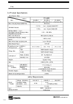
Page 16: ...rate Note3 350 g h Motor Rated Power 0 75 kW Operating current 50 60 Hz Primary current Note4 6 8 12 6 A 4 8 7 5 A 2 5 4 4 A Inlet NW40 Quick Flange Flange Size Outlet NW25 Quick Flange Name of article K 7 Synthetic oil Lubricant oil Quantity of oil 0 24 litter Weight Approx 54 kg Size 298W x 475L x 275H Atmosphere temperature 15 to 30 deg C Operating condition Relative Humidity 20 to 80 Condensat...

Page 17: ...rate with gas ballast valve fully opened Note 4 Actual value may not be in the range depending on facility Note 5 This describes tolerable voltage range and is not steady voltage Note 6 Do no use this product with over 250V even it is within the tolerable range Note 7 For more details about oversea safety standard contact one of our sales offices listed in the back ...

Page 18: ...t NW25 Gas ballast port Inlet NW40 5 CN2 CN1 Operation panel I O connector Power Input Main Switch Direction of ventilation Please secure the space for cooling front and rear side 100 mm or more lateal side 50 mm or more Single phase 100 200V Main Switch Power Input CN2 Operation panel CN1 I O connector Three phase 200V Cooling air inlet Cooling air inlet Cooling air outlet ...

Page 19: ... 6 Pumping Performance 0 100 200 300 400 500 600 700 800 1 0E 01 1 0E 00 1 0E 01 1 0E 02 1 0E 03 1 0E 04 1 0E 05 Pressure Pa Pumping speed L min Gas ballast valve ON Gas ballast valve OFF Note The gas ballast mechanism is an option ...

Page 20: ...n WARNING Lifting up the pump by crane or forklift must be operated by licensed worker and make sure surrounding area is secured When the pump is lifted do not get close to its underneath the pump may fall down and it may cause injury Use appropriate wire or crane for lifting up the weight of the pump Figure 4 1 shows that the angle of wire when lifting up the pump should be equal apportion CAUTIO...

Page 21: ... may be installed and maintained smoothly Be careful to make the temperature from 15 to 30 deg C and to make the humidity from 20 to 80 condensation must not exist around the pump while it is operating especially in closed place because that may cause dew condensation inside the pump Keep space 100mm or more at front and rear side 50mm or more at lateral side to secure good ventilation for cooling...

Page 22: ...rox 54kg To facilitate the maintenance work install the pump on the floor When moving pump on the uneven place please put the pump on the carriage After installation of the pump please remove eyebolts Please keep the removed eyebolts Fig 4 1 Fixing Position of the pump Fig 4 2 How to Fix the pump Adjusting level Liner for adjusting Please prepare required Pump base 30 Surface of the base should be...

Page 23: ...clean pipes without any foreign material for piping Don t install a heavy material directly at the inlet port and the outlet port otherwise a leak or damage will be caused to the connecting portions It is recommended to use a stainless flexible joint between the pump and a pipe Take care adhering of either any dust or foreign material to the flange seal surface And take care not to put the scar on...

Page 24: ...on Note 2 Use this pump pursuant to the voltage range stated in P 7 About Safety Standard of The Pump when operate it according to the oversea safety standard DANGER Turn off the main switch on the pump and disconnect power cable before servicing Do not supply power before completion of service work WARNING Wiring work must be done by qualified workers For US installations the EV A06 dry pump shou...

Page 25: ...ARNING Be sure to perform grounding otherwise an electric shock may be caused by electric leakage Use the wiring materials that correspond to the pump power Table 4 2 Wiring material Type EV A06 1 EV A06 2 EV A06 3 Applicable wire size AWG 12 3 5 mm2 AWG 14 2 0 mm2 Number of wicks 3 4 ...

Page 26: ...essory Note 2 Do not use cord reel for power supply as it may cause the case where pump dose not start due to voltage drop B How to connect wires Single phase and three phase 200Vtype EV A06 2 3 For pin connections of the power connector refer to Fig 4 4 Table 4 5 and Table 4 6 Table 4 5 CN1 Receptacle Pin Assign Phase Single phase 200V Three phase 200V Pin No EV A06 2 EV A06 3 X L Load R Y N Neut...

Page 27: ...acle Applicable wire size AWG 24 20 0 2 0 5mm2 Note Applicable plug and clump hood are not attached Please prepare by the equipment side Fig 4 6 I O connector CN2 D sub Connector Pin connections CONFIRMATION For Input signals Pin No 1 9 2 10 3 11 4 12 apply a voltage of 24V DC on the pump controller side Don t apply a voltage on the equipment side otherwise the controller may go wrong 8 15 1 9 DP ...

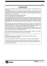
Page 28: ... The output signal pin No 6 7 14 is 1c no voltage relay contact outputs The contact capacity is AC230V 0 2A and DC30V 0 3A Please make the RESET Input signal pin No 2 10 Closed for 0 1 seconds or more When I O connector CN2 is used for remote control and monitoring use shielded cable to eliminate EMC noise Connect shield end to connector housing ...

Page 29: ...nnector that is standard accessory onto I O connector CN2 5 1 Operation Panel Running status can be checked by LED display on operation panel Fig 5 1 Operation panel Fig 5 2 Pump operation side 4 RUN Lamp 5 Monitor Lamp Hz 6 Monitor Lamp A 8 LED Display 7 LOCAL REMOTE Lamp 9 RUN Switch 11 ESC Switch 12 UP Switch 13 DOWN Switch 1 POWER Lamp 2 ALARM Lamp 3 PROGRAM Lamp 10 STOP RESET Switch 14 SET Sw...

Page 30: ...s frequency 6 MONITOR Lamp A Lights up when LED display indicates current 7 LOCAL REMOTE Lamp Lights up when running in local mode light out in remote mode 8 LED Indicator Indicate run time rotation speed and inverter 2ndary side current 9 RUN switch Starts up the pump Only in local mode 10 STOP REST Switch Stops the pump and reset 11 ESC Switch Switches between LED indicator and group code 12 Up ...

Page 31: ...Monitor lamp A lights up when it is displayed Data range Content Total run hour hrs 1 0 0 9999 Indicated by hour 2 1000 9999 Indicated by 10 hr Total electrified hour hrs 3 100 999 Indicated by 1000 hr 4 0 9999 Indicated by time Error count monitor Time 5 1000 6553 Indicated by 10 time d081 d086 Error monitor Last 6 errors available See P 47 how to use LED monitor section indicated when there is n...

Page 32: ...dication LED Display Data range Example Run hour time 1 0 0 9999 3333 3 333 hour 2 1000 9999 3333 33 330 hour Total run hour Total electrified hour 3 100 999 333 333 000 hour 4 0 9999 3333 3 333 time Error count monitor 5 1000 6553 3333 33 330 time ...

Page 33: ...stall shut off valve between the system and the pump Close this valve before the pump stops When condensable gas such as water vapor has been pumped please keep the pump running opening the inlet port for about one hour after pump operation Corrosion in the pump can be prevented by removing the residual with dry air As the pumped gas quantity is larger perform the dry air pumping for a longer time...

Page 34: ...tch on the controller is pressed during pump operation with driving connector under direct power input To restart the pump turn power off wait until LED light goes off then turn it back on 6 2 2 Operation by operation panel Please confirm the driving connector is not placed to I O connector CN2 START 1 Supply power to the pump Turn on the MAIN POWER switch on the pump The POWER LOCAL REMOTE lamp o...

Page 35: ...he time DP RUN Status signal will be put into a make state Pin No 13 6 5 Make sure that abnormality unusual noise and or vibration is not found after the pump starts STOP 1 Put the DP RUN Input signal from the I O connector CN2 into an open state Pin No 1 9 The pump will be stopped and the RUN Lamp on the operation panel will go out At the time DP RUN Status signal will be put into an open state P...

Page 36: ...d controller will come on The RUN Lamp on the operation panel will come on 3 Make sure that abnormality unusual noise and or vibration is not found after the pump starts STOP 1 Press the RUN STOP switch on the handheld controller The pump operation will stop and the RUN Lamp on the handheld controller will go out CONFIRMATION Do not detach the handheld controller during the operation The pump stop...

Page 37: ...the pump operating temperature the kind of condensable gas and its amount Turn off the gas ballast valve when you do not use condensable gas CONFIRMATION Always use gas ballast mechanism optional when pumping condensable gases When using gas ballast valve while the beginning operation of which the pump is still cold gas ballast capability cannot be fully performed If it is necessary to exhaust wat...

Page 38: ... Photo 6 1 Gas ballast specifications Inlet Outlet Gas ballast valve Photo 6 2 The pump of which gas ballast valve is installed Gas ballast valve Close Gas ballast valve Open 1 4 tube Fitting Check valve Valve Fig 6 1 How to open and close the gas ballast valve ...

Page 39: ...ervicing Do not supply power before completion of service work WARNING Pump remains hot during and or after operation Avoid direct skin contact otherwise it may cause burn Keep combustible materials away from the product Do not attempt to service the product when it is hot Do not remove packaging covers during operation When pump error arises press STOP RESET switch on the controller or apply rese...

Page 40: ... when it is hot Do not remove packaging covers during operation Perform leak check after piping maintenance Apply pressure form exhaust piping and pressurize up to 0 05 MPa for pressure leak check 7 3 Lubricant oil Check oil level regularly Oil level gauge is located at rear end of the pump See diagram 7 1 Oil level gauge position below The level may be lower than lower limit during the operation ...

Page 41: ...lace it on the plug then put it back and tighten securely 5 Perform leak check after the oil refill Photo 7 2 Filler plug and oil level gauge position CAUTION Use lubricant oil specified on P 18 3 4 Product specification section Do not overfill more than upper limit as it may damage the product Refill lubricant oil immediately when oil level is low as it may cause severe damages to the product Rep...

Page 42: ...to the condition of the usage When the gas to be pumped is very reactive or corrosive it may be necessary to have overhauled more than once a year The product may not be accepted if it was used for pumping arsenic gas or phosphorous gas Please consult with our business office beforehand 6 Turn around time and service procedure may be different for the product with special specifications Please con...

Page 43: ...roduct when it is hot Do not remove packaging covers during operation CAUTION Do not lift the pump by your self Lift the pump by hand with two 2 persons Do not use sling or the like to lift the pump as the handles are not designed to be used with slings Follow the procedure below when removing the pump from facility 1 Stop the pump and purge of the process gas with N2 gas completely 2 Stop supplyi...

Page 44: ...nto I O connector CN2 Some objects on the outside cover Take the objects away Vises to fix the outside cover are loosened Tighten the vises Resonance of flexible tubes for inlet exhaust Fix the resonant part Pump parts damages Pump replacement or overhaul is needed Cooling fan error Pump maintenance or parts replacement is needed Abnormal noise Intense vibration Pump error Pump replacement or over...

Page 45: ...ter error Pump error Needs to check and repair electric parts Needs to overhaul pump E14 Earth protection E15 Incoming high voltage protection E19 Temperature detection error E21 Fin temperature error E22 CPU communication error E25 Main circuit error E30 Driver error Inverter error Pump error There should be source of noise near the pump Consider plan to decrease its noise Needs to check and repa...

Page 46: ...ipheral unit to be returned eliminate toxic gas by charging inert gas When solutions and lubricating oil can be disposed of properly on the user side bleed them completely 3 Remove all the accessories which are attached to the equipment 4 Seal up the inlet port and outlet port of the pump by using blank flanges 5 Seal up the product to be returned if possible after putting them in a polyethylene c...

Page 47: ...duct to be returned i Applied process name ii Pollutant table Pollutant name Chemical symbol Precaution on Handling Action to be taken for accidental inhalation or touch 1 2 3 4 5 6 III Reason for return i Overhaul Failure Other ii Contents of failure IV Person in charge and where to contact Name signature Post Company name plant name Address Telephone FAX No TEL FAX Date of return ...

Page 48: ...LIVINGSTONE WEST LOTHIAN EH54 9DE U K PHONE 44 1506 460232 URL FAX 44 1506 460222 http www ebara com sg index php option com_frontpage Itemid 1 Service Locations CHINA http www ebara pm eu about us locations html SHANGHAI EBARA PRECISION MACHINERY CO LTD KOREA ZHANGJIANG HIGH TECHNIC PARK NO 76 LANE 887 EBARA PRECISION MACHINERY KOREA INC ZUCHONGZHI ROAD SHANGHAI 201203 CHINA PHONE 86 21 5131 7008...

Reviews: