Operating instructions
R4E250-CG01-01
Translation of the original operating instructions
ebm-papst Mulfingen GmbH & Co. KG
Bachmühle 2
D-74673 Mulfingen
Phone +49 (0) 7938 81-0
Fax +49 (0) 7938 81-110
info1@de.ebmpapst.com
www.ebmpapst.com
CONTENTS
1. SAFETY REGULATIONS AND NOTES
1
1. SAFETY REGULATIONS AND NOTES
Please read these operating instructions carefully before starting to work
with the device. Observe the following warnings to prevent malfunctions
or physical damage to both property and people.
These operating instructions are to be regarded as part of this device.
If the device is sold or transferred, the operating instructions must
accompany it.
These operating instructions may be duplicated and forwarded for
information about potential dangers and their prevention.
1.1 Levels of hazard warnings
1
1.1 Levels of hazard warnings
These operating instructions use the following hazard levels to indicate
potentially hazardous situations and important safety regulations:
DANGER
Indicates an imminently hazardous situation which, if not
avoided, will result in death or serious injury. Compliance with
the measures is mandatory.
WARNING
Indicates a potentially hazardous situation which, if not avoided,
could result in death or serious injury. Exercise extreme
caution while working.
CAUTION
Indicates a potentially hazardous situation which, if not avoided,
may result in minor or moderate injury or damage of property.
NOTE
A potentially harmful situation can occur and, if not avoided, can
lead to property damage.
1.2 Staff qualification
1
1.2 Staff qualification
The device may only be transported, unpacked, installed, operated,
maintained and otherwise used by qualified, trained and authorised
technical staff.
Only authorised specialists are permitted to install the device, to carry
out a test run and to perform work on the electrical installation.
1.3 Basic safety rules
1
1.3 Basic safety rules
Any safety hazards stemming from the device must be re-evaluated
once it is installed in the end device.
Observe the following when working on the unit:
;
Do not make any modifications, additions or conversions to the
device without the approval of ebm-papst.
1.4 Electrical voltage
1
1.4 Electrical voltage
;
Check the electrical equipment of the device at regular intervals, refer
to chapter 5.2 Safety test.
;
Replace loose connections and defective cables immediately.
DANGER
Electrical load on the device
Risk of electric shock
→ Stand on a rubber mat if you are working on an electrically
charged device.
WARNING
Terminals and connections have voltage even with a
unit that is shut off
Electric shock
→ Wait five minutes after disconnecting the voltage at all poles
before opening the device.
2
1.5 Safety and protective functions
2
1.6 Mechanical movement
2
1.7 Emission
2
1.8 Hot surface
2
1.9 Transport
2
1.10 Storage
2
1.11 Disposal
3
2. PROPER USE
4
3. TECHNICAL DATA
4
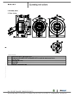
3.1 Product drawing
5
3.2 Nominal data
5
3.3 Technical features
5
3.4 Mounting data
5
3.5 Transport and storage conditions
6
4. CONNECTION AND START-UP
6
4.1 Connecting the mechanical system
6
4.2 Connecting the electrical system
7
4.3 Connection of the cables
8
4.4 Connection screen
9
4.5 Checking the connections
9
4.6 Switch on device
9
4.7 Switching off the device
9
5. MAINTENANCE, MALFUNCTIONS, POSSIBLE
CAUSES AND REMEDIES
10
5.1 Cleaning
10
5.2 Safety test
Item no. 10715-5-9970 · Revision 82542 · Release 2014-05-08 · Page 1 / 10
ebm-papst Mulfingen GmbH & Co. KG · Bachmühle 2 · D-74673 Mulfingen · Phone +49 (0) 7938 81-0 · Fax +49 (0) 7938 81-110 · info1@de.ebmpapst.com · www.ebmpapst.com


