background image

Page 1 of 11

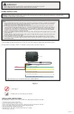
Installation Instructions

Wireless Camera/Monitor System

Failure to install or use this product according to manufacturer’s recommendations may result in property damage, serious bodily/personal injury, 

and/or death to you and those you are seeking to protect!  

!

WARNING!

1. Proper installation combined with operator training in the use, care, and maintenance of safety products are essential to ensure the safety of

    you and those you are trying to protect.

2. Exercise caution when working with live electrical connections.

3. This product must be properly grounded. Inadequate grounding and/or shorting of electrical connections can cause high current arcing, which 

    can cause personal injury and/or severe vehicle damage, including fire.

4. Proper placement and installation are vital to the performance of this safety product. Install this product so that the performance of the system 

    is maximized and the controls are placed within convenient reach of the operator so that s/he can operate the system without losing eye contact 

    with the roadway.

5. It is the responsibility of the vehicle operator to ensure during use that all features of this product work correctly. In use, the vehicle operator 

    should ensure the field-of-view of the camera/monitor is not blocked by vehicle components (i.e., open trunks or compartment doors), people, 

    vehicles, or other obstructions.

6. Never take the right-of-way for granted. It is your responsibility to be sure you can proceed safely before entering an intersection, driving 

    against traffic, responding at a high rate of speed, walking on or around traffic lanes.

7. This equipment is intended for use by authorized personnel only. The user is responsible for understanding and obeying all laws regarding 

     safety products. Therefore, the user should check all applicable city, state, and federal laws and regulations. The manufacturer assumes no 

     liability for any loss resulting from the use of this safety product.

Do not install and/or operate this safety product unless you have read and understand the safety information

contained 

Installation, Wiring and Function


Caution!

 When drilling into any vehicle surface, make sure that the area is free from any electrical wires, fuel lines, 

vehicle upholstery, etc. that could be damaged.

!

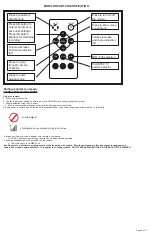
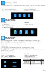
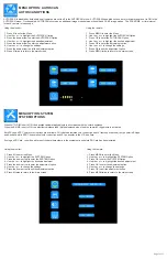
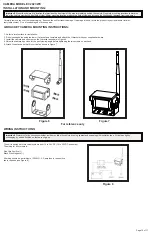
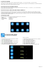
CAMERA SYSTEM MODEL EC7008-WK

OPERATING INSTRUCTIONS:

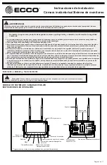
M

S

Digital Color LED Screen

Power

Menu

Record/Select

Volume Decrease/Menu

          Navigation

Volume Increase/Menu Navigation

Camera Channel Select

Dimming Sensor

Loudspeaker

U-Support Bracket

Pedestal Mount Slot

Mini SD Card Slot

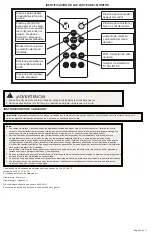
Remote

Control

Sensor

Ecante-5

Summary of Contents for EC2027-WC

Page 1: ...he vehicle operator should ensure the field of view of the camera monitor is not blocked by vehicle components i e open trunks or compartment doors people vehicles or other obstructions 6 Never take the right of way for granted It is your responsibility to be sure you can proceed safely before entering an intersection driving against traffic responding at a high rate of speed walking on or around ...

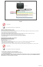
Page 2: ...chassis components preferably directly to the vehicle battery 6 Circuit breakers are very sensitive to high temperatures and will false trip when mounted in hot enviroments or operated close to their capacity The unit is designed for electrical systems from 12 to 24 VDC 10 to 30 VDC extremes Wiring options are as follows in Figure 1 All wiring should be a minimum of 26 AWG A 3 amp fuse in the posi...

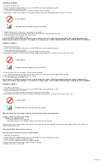
Page 3: ... adding additional cameras press SEL on the remote A This will take you to CAMERA Two If pairing process is followed properly monitor will stay paired with camera Should camera power off or lose signal reapply power to camera and monitor camera will repair This applies to all configurations DO NOT PRESS PAIR BUTTON ON THE BACK OF THE CAMERA Page 3 of 11 MONITOR PARTS IDENTIFICATION OK SEL MENU PAI...

Page 4: ...e if adding multiple cameras 6 If adding additional cameras press SEL on the remote A This will take you to CAMERA Four If pairing process is followed properly monitor will stay paired with camera Should camera power off or lose signal reapply power to camera and monitor camera will repair This applies to all configurations DO NOT PRESS PAIR BUTTON ON THE BACK OF THE CAMERA PAIRING 4th CAMERA 1 Cl...

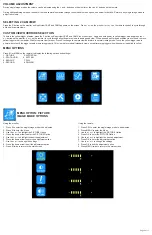
Page 5: ...gger override is working properly This view will override all standard views except reversing trigger wire when power is applied to yellow MENU OPTIONS SELECTING 2 CAM VIEW Press the S button on the monitor until split view CAM1 and CAM2 appears on the screen Press or on the monitor or or on the remote control to cycle through all the split camera views MENU OPTION PICTURE IMAGE MODE OPTIONS Using...

Page 6: ...ghlight the RECORD Option 3 Press the down arrow to enter the RECORD Option 4 Use the or to highlight the desired adjustment 5 Press M twice to return to the main screen Using the remote 1 Press MENU to enter the Menu 2 Use the or to highlight the RECORD Option 3 Press OK to enter the RECORD Option 4 Use the or to highlight the desired adjustment 5 Press MENU twice to return to the main screen Ena...

Page 7: ...TEM SYSTEM OPTIONS Using the monitor 1 Press M to enter the Menu 2 Use the or to highlight the SYSTEM Option 3 Press the down arrow to enter the SYSTEM Option 4 Use the or to highlight the desired adjustment 5 Press the down arrow to enter the adjustment option 6 Use the or to change the settings 7 Press the down arrow to exit the adjustment option 8 Press M twice to return to the main screen Usin...

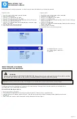
Page 8: ...p a passcode In order to access the menu after initial setup you will need the passcode Verify Media Player has most up to date software if given a system error on playback MONITOR MODEL EC7008 WM INSTALLATION AND MOUNTING WARNING To prevent accidental shock DO NOT OPEN THE MONITOR CASE Opening the monitor case will expose the inside of the monitor to conditions that could adversely affect perform...

Page 9: ...ors 2 Route wiring using grommets and sealant when passing through compartment walls Minimize the number of splices to reduce voltage drop High ambient temperatures e g under hood will significantly reduce the current carrying capacity of wires fuses and circuit breakers All wiring should conform to the minimum wire size and other recommendations of the manufacturer and be protected from moving pa...

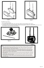
Page 10: ... the U bracket with user supplied hardware 3 Install the camera and sun visor on the U bracket as shown in Figure 6 4 Adjust the camera s position for the best viewing angle before tightening the two screws on each end 5 Attach the antenna so that it is vertical as shown in Figure 7 Figure 6 CAMERA MODEL EC2027 WC INSTALLATION AND MOUNTING For reference only Figure 7 WIRING INSTRUCTIONS Important ...

Page 11: ...IES EXPRESSED OR IMPLIED THE IMPLIED WARRANTIES FOR MERCHANTABILITY QUALITY OR FITNESS FOR A PARTICULAR PURPOSE OR ARISING FROM A COURSE OF DEALING USAGE OR TRADE PRACTICE ARE HEREBY EXCLUDED AND SHALL NOT APPLY TO THE PRODUCT AND ARE HEREBY DISCLAIMED EXCEPT TO THE EXTENT PROHIBITED BY APPLICABLE LAW ORAL STATEMENTS OR REPRESENTATIONS ABOUT THE PRODUCT DO NOT CONSTITUTE WARRANTIES Remedies and Li...

Page 12: ...áfico de responder bien ante velocidades altas y de caminar correctamente en o cerca de los carriles de tránsito 7 El personal autorizado es el único que debe utilizar estos equipos El usuario es responsable de entender y obedecer todas las leyes relacionadas a los productos de seguridad Por tanto el usuario debe verificar todas las leyes y regulaciones federales estatales y locales aplicables El ...

Page 13: ...nda usar bloques de terminales o conexiones soldadas cuando se intube por contracción para proteger las conexiones No usa conectores de por desplazamiento en aislamiento p ej conectores tipo Scotchlock de 3M 2 Enrute el cableado utilizando pasacables y sellante cuando atraviese las paredes del compartimiento Minimice el número de empalmes para reducir la caída de tensión Las temperaturas ambiente ...

Page 14: ...onitor pasará de forma predeterminada a Scan Mode Modo de exploración con la Cámara 1 6 Con el botón SEL Seleccionar del control remoto elija la Cámara 1 para realizar el emparejamiento 7 NO encienda la cámara INSTRUCCIONES DE INSTALACIÓN Las cámaras se deben emparejar secuencialmente Uso del control remoto 1 Haga clic en el menú del control remoto 2 Utilice la flecha derecha con la etiqueta Volum...

Page 15: ...resione SEL Seleccionar en el control remoto A Esto le llevará a la CÁMARA cuatro Si el proceso de emparejamiento se realiza correctamente el monitor permanecerá emparejado con la cámara Si la cámara se apaga o pierde la señal vuelva a conectar la alimentación y el monitor o la cámara se restaurarán Esto se aplica a todas las configuraciones NO PRESIONE EL BOTÓN DE EMPAREJAMIENTO EN LA PARTE POSTE...

Page 16: ...ione OK para salir de la opción de ajuste 9 Presione MENÚ dos veces para regresar a la pantalla principal IMAGE AJUSTE DEL VOLUMEN Durante los modos de imagen única el volumen se puede ajustar usando los botones y en el monitor o los botones y en el control remoto Durante los modos de imagen dividida cuádruple el audio de una cámara se selecciona a través de la opción del menú de audio dividido ve...

Page 17: ...altar la Opción GRABACIÓN 3 Presione la flecha hacia abajo para ingresar a la Opción GRABACIÓN 4 Use o para resaltar el ajuste deseado 5 Presione M dos veces para regresar a la pantalla principal Usando el control remoto 1 Presione MENÚ para ingresar al Menú 2 Use o para resaltar la Opción GRABACIÓN 3 Presione OK para ingresar a la Opción GRABACIÓN 4 Use o para resaltar el ajuste deseado 5 Presion...

Page 18: ... a la pantalla principal Usando el control remoto 1 Presione MENÚ para ingresar al Menú 2 Use o para resaltar la Opción SISTEMA 3 Presione OK para ingresar a la Opción SISTEMA 4 Use o para resaltar el ajuste deseado 5 Presione OK para ingresar a la opción de ajuste 6 Use o para cambiar las configuraciones 7 Presione OK para salir de la opción de ajuste 8 Presione MENÚ dos veces para regresar a la ...

Page 19: ...igo Para poder tener acceso al menú luego de la configuración inicial necesitará el código de acceso Verify Media Player has most up to date software if given a system error on playback MODELO DEL MONITOR EC7008 WM INSTALACIÓN Y ENSAMBLAJE ADVERTENCIA Para evitar una descarga accidental NO ABRA EL COMPARTIMIENTO DEL MONITOR Abrir el compartimiento del monitor expondrá las partes internas del monit...

Page 20: ...palmes para reducir la caída de tensión Las temperaturas ambiente altas p ej debajo de la cajuela reducirán significativamente la capacidad de transmisión de la corriente de cables fusibles e interruptores Todo el cableado debe estar en conformidad con el tamaño mínimo de cable y otras recomendaciones del fabricante además de estar protegido de las partes móviles y las superficies calientes Deben ...

Page 21: ... los accesorios suministrados al usuario 3 Instale la cámara y el visor de sol en la abrazadera en U como se muestra en la Figura 6 4 Ajuste la posición de la cámara para conseguir el mejor ángulo de visualización antes de ajustar los dos tornillos a cada extremo 5 Fije la antena de tal forma que esté vertical CAMÉRA MODÈLE EC2027 WC INSTALLATION ET MONTAGE Solo para referencia Figura 6 Figura 7 3...

Page 22: ... compra EL DAÑO A LAS PIEZAS O LOS PRODUCTOS CAUSADO POR LA ALTERACIÓN ACCIDENTE ABUSO MAL USO NEGLIGENCIA MODIFICACIONES NO AUTORIZADAS FUEGO U OTRO PELIGRO INSTALACIÓN U OPERACIÓN INCORRECTAS O NO REALIZAR EL MANTENIMIENTO DE ACUERDO CON LOS ROCEDIMIENTOS DE MANTENIMIENTO ESTABLECIDOS EN LAS INSTRUCCIONES DE INSTALACIÓN Y DE OPERACIÓN DEL FABRICANTE ANULA ESTA Garantía LIMITADA Exclusión de otra...

Page 23: ...le trafic la conduite à un rythme élevé de vitesse la marche à travers ou autour des voies de circulation 7 Cet équipement n est destiné à être utilisé que par le personnel autorisé L utilisateur est responsable de comprendre et d obéir toutes les lois concernant la sécurité des produits Par conséquent l utilisateur doit observer l ensemble des lois et règlements fédéraux de la ville et de l état ...

Page 24: ...ec des tuyaux thermorétractables pour protéger les connexions N utilisez pas de connecteurs autodénudants p ex connecteurs 3M type Scotchlock 2 Acheminer le câble à l aide d oeillets et de joints d étanchéité lors du passage à travers les parois du compartiment Réduisez le nombre d épissures pour réduire la chute de tension Des températures ambiantes élevées p ex sous capot réduiront considérablem...

Page 25: ...layage avec la caméra 1 6 À l aide de la télécommande appuyez sur le bouton SEL sélectionner de la télécommande puis sélectionnez Caméra 1 pour effectuer l appariement 7 NE mettez PAS la caméra sous tension INSTRUCTIONS D INSTALLATION Les caméras doivent être appariées séquentiellement Utilisation de la télécommande 1 Appuyez sur le bouton Menu de la télécommande 2 Utilisez la flèche vers la droit...

Page 26: ...i vous ajoutez d autres caméras appuyez sur le bouton SEL sélectionner de la télécommande A Vous accédez alors à CAMÉRA 4 Si le processus de couplage est correctement suivi le moniteur reste apparié avec la caméra Si la caméra s éteint ou perd le signal remettez la sous tension et la connexion entre moniteur et la caméra se réparera Ceci s applique à toutes les configurations N APPUYEZ PAS SUR LE ...

Page 27: ...EX DE CAMÉRA Appuyez sur le bouton S sur l écran jusqu à ce que l affichage Duplex CAM1 et CAM2 s affiche à l écran Appuyez sur ou sur l écran ou ou sur la télécommande pour parcourir tous les affichages Duplex de la caméra OPTION DE MENU IMAGE OPTIONS DU MODE IMAGE Utilisation de l écran 1 Appuyez sur S pour accéder au mode image unique à ajuster 2 Appuyez sur M pour accéder au Menu 3 Utilisez le...

Page 28: ...ez sur la flèche vers le bas pour entrer l option ENREGISTREMENT 4 Utilisez les touches ou pour mettre en évidence le réglage souhaité 5 Appuyez sur M deux fois pour revenir à l écran principal Utiliser la télécommande 1 Appuyez sur Menu pour accéder au Menu 2 Utiliser les signes ou pour mettre en évidence l option ENREGISTREMENT 3 Appuyez sur OK pour entrer l option ENREGISTREMENT 4 Utiliser les ...

Page 29: ...ir à l écran principal OPTION DE MENU SYSTÈME OPTIONS DU SYSTÈME Utilisation de l écran 1 Appuyez sur M pour accéder au Menu 2 Utilisez les touches ou pour mettre en évidence l option SYSTÈME 3 Appuyez sur la flèche vers le bas pour entrer l option SYSTÈME 4 Utilisez les touches or pour mettre en évidence le réglage souhaité 5 Appuyez sur la flèche vers le bas pour entrer l option de réglage 6 Uti...

Page 30: ... l écran principal Voir la section enregistrement pour la configuration du code d accès Pour accéder au menu après la configuration initiale vous aurez besoin du code d accès Verify Media Player has most up to date software if given a system error on playback MODÈLE D ÉCRAN EC7008 WM INSTALLATION ET MONTAGE AVERTISSEMENT Pour éviter tout risque de choc N OUVREZ PAS LE BOÎTIER DE L ÉCRAN L ouvertur...

Page 31: ...étanchéité lors du passage à travers les parois du compartiment Réduisez le nombre d épissures pour réduire la chute de tension Des températures ambiantes élevées p ex sous capot réduiront considérablement la capacité de transport du courant des câbles fusibles et disjoncteurs Tout le câblage doit être conforme à la taille minimale et d autres recommandations du fabricant et être protégé des pièce...

Page 32: ...en U comme illustré à la Figure 6 4 Ajustez la position de la caméra pour un meilleur angle de vue avant de serrer les deux vis sur chaque extrémité 5 Fixez l antenne de manière à ce qu elle soit verticale CAMÉRA MODÈLE EC2027 WC INSTALLATION ET MONTAGE Pour référence seulement Figure 6 Figure 7 INSTRUCTIONS DE CÂBLAGE Important Imperméabilisez toutes les connexions à l intérieur ou à l extérieur ...

Page 33: ...E NÉGLIGENCE DE MODIFICA TIONS NON AUTORISÉES D UN INCENDIE OU DE TOUT AUTRE DANGER DE L INSTALLATION OU D UNE UTILISATION INCORRECTE OU D UN DÉFAUT D ENTRETIEN CONFORME AUX PROCÉDURES DE MAINTENANCE DÉCRITES DANS LES CONSIGNES D INSTALLATION ET D UTILISATION DU FABRICANT ANNULENT CETTE GARANTIE LIMITÉE Exclusion d autres garanties LE FABRICANT N ÉMET AUCUNE AUTRE GARANTIE QU ELLE SOIT EXPRESSE OU...

Page 34: ...für sorgen dass das Sichtfeld der Kamera Überwachungsanlage während der Verwendung nicht durch Fahrzeugkomponenten z B offene Kofferraumklappe oder Türen Personen Fahrzeuge oder andere Hindernisse blockiert wird 6 Sehen Sie das Vorfahrtsrecht niemals als selbstverständlich an Es liegt in Ihrer Verantwortung sicherzustellen dass keine Gefahr für Sie besteht bevor Sie eine Kreuzung überqueren entgeg...

Page 35: ...ißen Umgebungen montiert oder nahe ihrer Kapazitätsgrenze betrieben werden Das Gerät ist für elektrische Systeme von 12 bis 24 VDC Extreme 10 bis 30 VDC ausgelegt Die Verdrahtung erfolgt wie in Abbildung 1 gezeigt Alle Kabel sollten mindestens über 26 AWG verfügen Es ist eine 3 A Sicherung in der positiven Leitung des Monitors erforderlich EC7008 WK Stromversorgung ROT Masse SCHWARZ Auslösekabel K...

Page 36: ...ung die Auswahltaste SEL A Dadurch gelangen Sie zur zweiten KAMERA Wenn der Kopplungsvorgang wie vorgesehen durchgeführt wird bleibt die Kopplung des Monitors mit der Kamera erhalten Wenn die Kamera ausgeschaltet wird oder das Signal verloren geht schalten Sie die Kamera erneut ein und der Monitor die Kamera wird wiederherg estellt Dies gilt für alle Konfigurationen DRÜCKEN SIE NICHT DIE KOPPLUNGS...

Page 37: ...Wenn Sie weitere Kameras hinzufügen drücken Sie auf der Fernbedienung die Auswahltaste SEL A Dadurch gelangen Sie zur zweiten KAMERA 4 Wenn der Kopplungsvorgang wie vorgesehen durchgeführt wird bleibt die Kopplung des Monitors mit der Kamera erhalten Wenn die Kamera ausgeschaltet wird oder das Signal verloren geht schalten Sie die Kamera erneut ein und der Monitor die Kamera wird wiederherg estell...

Page 38: ...Ansicht gezeigt wird Wenn das gelbe Kabel an die Stromversorgung angeschlossen wird hat diese Ansicht Vorrang gegenüber allen Standardansichten mit Ausnahme des Auslösekabels für die Rückfahrkamera MENÜOPTIONEN SAUSWAHL EINER ANSICHT MIT 2 KAMERAS Drücken Sie die Taste S am Monitor bis der Bildschirm in CAM1 und CAM2 aufgeteilt wird Drücken Sie oder auf dem Monitor bzw oder auf der Fern bedienung ...

Page 39: ...amerabildern kann die Lautstärke nicht eingestellt werden MENÜOPTION MIR FLIP MIR UMDREHEN OPTIONEN ZUM DREHEN UMKEHREN Über den Monitor 1 Drücken Sie S um in den Einzelbildmodus zu gelangen der angepasst werden soll 2 Drücken Sie M um in das Menü zu gelangen 3 Drücken Sie bzw um die Option MIR FLIP MIR UMDREHEN hervorzuheben 4 Drücken Sie den Abwärtspfeil um die Option MIR FLIP MIR UMKEHREN aufzu...

Page 40: ...rtspfeil um die Option SYSTEM aufzurufen 4 Heben Sie mit den Tasten bzw die gewünschte Einstellungsoption hervor 5 Drücken Sie den Abwärtspfeil um die Einstellungsoption aufzurufen 6 Ändern Sie die Einstellung mit den Tasten und 7 Drücken Sie den Abwärtspfeil um die Einstellungsoption zu verlassen 8 Drücken Sie zweimal M um zum Hauptbildschirm zurückzukehren Über die Fernbedienung 1 Drücken Sie ME...

Page 41: ...tung des Passcodes finden Sie im Abschnitt Record Aufnahme Sie benötigen den Passcode um nach der Ersteinrichtung auf das Menü zuzugreifen Vergewissern Sie sich ob der Media Player die aktuellste Software hat wenn bei der Wiedergabe ein Fehler auftritt MONITORMODELL EC7008 WM INSTALLATION UND MONTAGE WARNUNG Um einen unabsichtlichen elektrischen Schock zu vermeiden ÖFFNEN SIE DAS MONITORGEHÄUSE NI...

Page 42: ... des Typs 3M Scotchlok 2 Verwenden Sie Tüllen und Dichtungsmittel um Kabel durch Trennwände zu verlegen Minimieren Sie die Anzahl der Spleiße um den Spannungsabfall zu verringern Hohe Umgebungstemperaturen z B im Motorraum verringern die Strombelastbarkeit von Kabeln Sicherungen und Leistungsschaltern erheblich Alle Kabel sollten die Mindestkabelgröße und andere Empfehlungen des Herstellers erfüll...

Page 43: ...genen Befestigungsmaterialien 3 Bringen Sie die Kamera und die Sonnenblende wie in Abbildung 6 gezeigt an der U Halterung an 4 Stellen Sie die Kamera so ein dass Sie den besten Blickwinkel haben und ziehen Sie dann die beiden Schrauben an den Enden fest 5 Bringen Sie die Antenne so an dass sie vertikal ausgerichtet ist wie in Abbildung 7 dargestellt Abbildung 6 KAMERAMODELL EC2027 WC INSTALLATION ...

Page 44: ...erbrauch Max 6W Lautsprecher 1 5 W 8 Betriebstemperatur 20 C bis 70 C Luftfeuchtigkeit max 90 Lagertemperatur 30 C bis 80 C Luftfeuchtigkeit max 90 Kamera EC2027 WC Bildgebendes Gerät 8 5 mm 1 3 CMOS TV System PAL NTSC Array Größe 728x488 Pixels Erkennungsbereich 4 6228mm x 3 6112mm Scanningsystem 2 1 Zeilensprung Synchr System Integriert Auflösung 500 TV Zeilen Min Beleuchtung 0 1 Lux Tag 0 Lux m...

Page 45: ...HT KONFORME PRODUKT BEZAHLT HAT UNTER KEINEN UMSTÄNDEN ÜBER STEIGT DIE AUS DIESER BESCHRÄNKTEN GARANTIE ODER EINEM ANDEREN ANSPRUCH IM ZUSAMMENHANG MIT DEN PRODUKTEN VON ECCO ENTSTE HENDE HAFTUNG VON ECCO DEN KAUFPREIS DES PRODUKTES ZUM ZEITPUNKT DES URSPRÜNGLICHEN ERWERBS DURCH DEN KÄUFER UNTER KEINEN UMSTÄNDEN HAFTET ECCO FÜR ENTGANGENE GEWINNE KOSTEN FÜR ERSATZGERÄTE ODER ARBEITSAUFWAND SACHSCH...

Reviews: