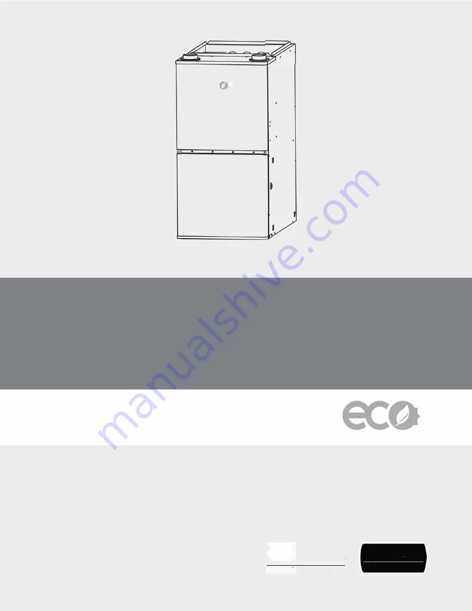
background image

C)

�-

EC 

er 

•·

,  I 

C) 

Ecoer 96% AFUE Gas Furnace MGH96 Model

Condensing Gas Furnace 

Installation, Operation, and Maintenance  Manual 

,��

IHliiJWJiM;I 

lntertek 

3124627 

er 

A.'1�1 CERTIFIED

® 

www ahrid1rectory org 

- - - -

Res1dent1alFurnaces 

D0E10CFRPart430 

Summary of Contents for MGH96

Page 1: ...Ecoer 96 AFUEGas Furnace MGH96 Model Condensing Gas Furnace Installation Operation and Maintenance Manual IHliiJWJiM I lntertek 3124627 er A 1 1 CERTIFIED www ahrid1rectory org Res1dent1alFurnaces D0...

Page 2: ...2 Ecoer 96 AFUE Gas Furnace Installation Operation Maintenance 07 2020 Ecoer Inc Data subject to change...

Page 3: ...ns 39 10 1 115V Wiring 39 10 2 Electrical Connection to J box 40 10 3 Power Cord Installation in Furnace J box 40 10 4 BX Cable Installation in Furnace J box 40 10 5 24 V Wiring 40 10 6 Accessories Fi...

Page 4: ...nformation Manual for more information SERVICER Use the information in this booklet to service the appliance and affix the booklet adjacent to the appliance after servicing WARNING FIRE OR EXPLOSION H...

Page 5: ...g outside the space containing the furnace See Section 7 5 Air Ducts A gas fired furnace for installation in a residential garage must be installed as specified in the warning box in Section 6 Locatio...

Page 6: ...o light the burner by hand BEFORE OPERATING smell all around the appliance area for gas Be sure to smell next to the floor because some gas is heavier than air and will settle to the floor WARNING A C...

Page 7: ...r Inlet Gas Pipe Entry Electrical Entry Condensate Drain Thermostat Wiring 24 610mm 26 1 2 672mm 25 3 4 655mm Combustion Air Inlet Vent Outlet Dimensions FurnaceModel A Cabinet Width In mm D Supply Ai...

Page 8: ...d must not be vented in common with other gas fired appliances For installations in Canada refer to Section 8 4 Combustion Air Venting of this manual Construction through which vent air intake pipes m...

Page 9: ...ction 7 Installation of this manual for more information Figure 4 1 2 3 4 1 2 3 4 4 Codes and Standards Follow all national and local codes and standards in addition to these instructions The installa...

Page 10: ...below during furnace installation and servicing to protect the furnace electronic control Precautions will prevent electrostatic discharges from personnel and hand tools which are held during the pro...

Page 11: ...parts containing flue gas which could leak into the living space Air for combustion must not be contaminated by halogen compounds which include fluoride chloride bromide and iodide These elements can...

Page 12: ...a flame rollout and or drawing combustion products into the structure The furnace is controlled by a thermostat It may not be hot wired to provide heat continuously to the structure without thermostat...

Page 13: ...7 BOTTOM CLOSURE PANEL BOTTOM FILLER PANEL SCREW SCREW Removing bottom closure panel Figure 8 Upflow Installation Tilt the unit slightly minimum 1 2 12 7 mm to maximum of 3 4 19 mm from back to front...

Page 14: ...ace on bottom or either the left hand LH or right hand RH side See Figure 9 The furnace can be hung from floor joists rafters or trusses or installed on a non combustible platform blocks bricks or pad...

Page 15: ...commended to add foam insulation around the drain line and heat tracing may also be necessary based on the application Leveling Leveling ensures proper condensate drainage from the heat exchanger and...

Page 16: ...FURNACE IS LEVEL FROM END TO END AND HAS A SLIGHT FORWARD TILT WITH THE FRONT OF THE FURNACE 3 4 BELOW THE BACK OF THE FURNACE TILT OUTWARD TO ALLOW FOR DOOR AND CIRCULATOR BLOWER REMOVAL HOLD DOWN NU...

Page 17: ...lope toward the drain Do not trap the drain line in any other location than at the drain trap supplied with the furnace Do not route the drain line outside where it may freeze 7 3 1 Standard Right Han...

Page 18: ...remove 2 caps on the side where trap is mounted Mount trap with manufacturer provided screws 4 Remove cap from the inducer drain port see Fig 13 Figure 13 5 Connect 16 mm hose between condensate colle...

Page 19: ...nt outlet pipe Use filed supplied straight 2 diameter pipe If 3 diameter pipes are used use a field supplied transition 6 Use provided or field supplied if applicable mounting bracket to mount drain t...

Page 20: ...ed elbow and metal hose clamp to make flue vertical Elbows should be as close to the furnace as possible Connect the vent outlet pipe 6 Use provided or field supplied if applicable mounting bracket to...

Page 21: ...one port Make sure that black port positive is connected to the lower position tap on condensate collector box and gray port negative to higher tap of condensate box Connecting incorrectly will resul...

Page 22: ...disposable filters are used air passage through filters should be increased to twice the size of original air opening by using a transition duct or using two filters in V shape see Fig 19 in normal d...

Page 23: ...m combustible materials and the supply air ductwork for a distance of 36 inch horizontally from the furnace See NFPA 90B or local code for further requirements Ductwork acoustical treatment Metal duct...

Page 24: ...5 54 2 Temp Rise 2nd stage 56 6 58 4 60 2 62 3 64 Mid CFM 1044 1002 968 931 886 841 805 767 718 677 Temp Rise 1st stage 40 8 43 4 45 8 50 5 50 9 54 0 57 6 60 8 64 4 Temp Rise 2nd stage Mid L CFM 825 7...

Page 25: ...1560 1506 1453 1402 1350 Temp Rise 1st stage 35 8 36 9 38 2 39 6 41 0 42 6 Temp Rise 2nd stage 48 8 50 3 51 8 53 4 55 0 56 8 58 8 60 9 63 1 Mid L CFM 1487 1417 1360 1296 1241 1183 1123 1064 1005 941...

Page 26: ...mum Equivalent Pipe Length lists the maximum equivalent length of pipe allowed for each model of furnace The equivalent length of elbows is shown in Table 7 Equivalent Length of Fittings The equivalen...

Page 27: ...10 feet of 3 pipe 3 45 standard elbow 5 feet of 3 pipe 2 corrugated connector 10 feet of 2 pipe 3 corrugated connector 10 feet of 3 pipe Table 7 Equivalent Length of Fittings Example An 80 000 BTUH f...

Page 28: ...tilated combustion air systems from the furnace to the attic or crawl space termination CAUTION Solvent cements are flammable and must be used in well ventilated areas only Keep them away from heat sp...

Page 29: ...dance with local installation codes and the requirements of the gas supplier J Clearance to nonmechanical air supply inlet to building or the combustion air inlet to any other appliance 12 30 5 cm for...

Page 30: ...ion air pipes terminate in the same atmospheric zone Refer to Figures 25 or 26 Figure 24 12 Min 12 Min Exhaust Exhaust Maintain 12 minimum clearance above highest anticipated snow level Maximum 24 abo...

Page 31: ...gure 31 for attic and crawl space termination Only the combustion air intake may terminate in the attic The vent must terminate outside 8 6 2 Outdoor Combustion Air Combustion Air Intake Vent Connecti...

Page 32: ...air may need to be provided using the methods described in A confined space section A confined space is an area with less than 50 cu ft 1 42m3 per 1 000 Btu hr 0 2928 kW input rating for all of the ap...

Page 33: ...the confined space shall communicate directly or by means of ducts with the outdoors crawl spaces or attic spaces 2 One permanent opening commencing within 12 in 305 mm of the top of the enclosure sh...

Page 34: ...operation while all other appliances connected to the venting system are not in operation 1 Inspect the venting system for proper size and horizontal pitch Determine that there is no blockage restrict...

Page 35: ...es The furnace must be equipped to operate on the type of gas applied This includes any conversion kits required for alternate fuels and or high altitude Inlet gas supply pressures must be maintained...

Page 36: ...ormation provided by the gas supplier to determine the proper orifice size US installation InputRate KBTU H Number of burners Elevation Ft Elevation Ft Elevation Ft Elevation Ft Elevation Ft 0 2000 20...

Page 37: ...equipment damage due to underfiring of equipment use the proper size of natural propane gas piping needed when running pipe from the meter tank to the furnace When sizing a trunk line be sure to inclu...

Page 38: ...the installer must supply the following fittings starting from the gas valve 90 degree elbows 2 Close nipple Straight pipe to reach the exterior of the furnace A ground joint union drip leg and manual...

Page 39: ...s sufficient to handle load imposed by this equipment Refer to rating plate or Table 17 page 41 for equipment electrical specifications Make all electrical connections in accordance with National Elec...

Page 40: ...ds as shown in Fig 36 Use best practices NEC in U S for wire bushings strain relief etc 13 Reinstall cover to J Box Do not pinch wires between cover and bracket 10 3 Power Cord Installation in Furnace...

Page 41: ...2000 10 5 95 40 70 22 39 20 14 170 77 Table 17 Ratings Physical Electrical Data Annual Fuel Utilization Efficiency AFUE numbers are determined in accordance with DOE Test procedures National Electric...

Page 42: ...IRING 208 230V THREE PHASE 208 230V SINGLE PHASE BLOWER DOOR SWITCH WHT BLK WHT BLK NOTES ConnectY1 Y Y2 terminal in furnace as shown for proper blower operation Some thermostats require a C terminal...

Page 43: ...s also equipped with a self diagnosing electronic control module In the event a furnace component is not operating properly the control module LED will flash on and off in a factory programmed sequenc...

Page 44: ...etry sequence The retry sequence provides a 60 second wait with the inducer interpurge following an unsuccessful ignition attempt flame not detected After this wait the ignition attempt is restarted T...

Page 45: ...utlet pressure barb fitting of valve to overlap at least 3 8 4 Turn ON system power and set thermostat to a call for heat 5 Using a leak detection solution or non chlorine soap suds check for leaks at...

Page 46: ...n the unit rating plate 5 Turn ON gas and relight appliances turned off in step 1 Ensure all the appliances are functioning properly and that all pilot burners are operating 11 7 Temperature Rise Adju...

Page 47: ...A Mid H 4 Mid 3 High 5 Mid 3 MGH96M080C4A Mid H 4 Mid 3 High 5 Mid 3 MGH96M100C5A Mid 3 Mid L 2 Mid H 4 Mid L 2 MGH96M100D5A Mid 3 Mid L 2 Mid 3 Mid L 2 MGH96M120D5A Mid H 4 Mid 3 Mid H 4 Mid 3 Table...

Page 48: ...mounted limit switches are located beside the blower housing They are temperature sensors which are automatically reset They are used to prevent overheating by hot air when the furnace is installed ho...

Page 49: ...es 4 Discharge your body to ground before removing a new control from its container Follow steps 1 through 3 if installing the control on a furnace Return any old or new controls to their containers b...

Page 50: ...h open with inducer on Pressure switch cycle lockout High fire pressure switch open with high inducer on Pressure switch hose blocked pinched or connected improperly blocked flue or weak induced draft...

Page 51: ...perate 10 FLASH Gas valve fault code Valve receives voltage from a short Control module failure 1 Correct the wire connection 2 Replace control module Turn power OFF prior to repair Furnace fails to o...

Page 52: ...filter s at the time of installation Filter maintenance Improper filter maintenance is the most common cause of inadequate heating or cooling performance Clean permanent filter or replace disposable f...

Page 53: ...ractor installer or service agency can clean the burners 15 7 Inspecting the Heat Exchanger Qualified Service Technicians Only NOTICE If the heat exchangers get a heavy accumulation of soot and carbon...

Page 54: ...me Sensor 3 Chamber Limit Switch Fixed 4 Condensate Overflow Switch 5 Inducer 6 Door Switch 7 Integrated Control Module 8 Blower 9 Transformer 10 Condensate Trap 11 Juction Box Please contact your loc...

Page 55: ...PRGH 05 05 1 1 09 09 09 09 1 1 36 36 09 09 36 36 72 72 0 52 0 52 05 05 3 3 1 1 1 1 1 1 225 225 6 7 6 7 81 7 21 2 81 7 21 2 1 1 1 6 211 7 6 211 7 1 1 1 1 5 1 5 1 1 1 1 1 1 1 1 1 05 1 05 1 86 8 6 80 5 8...

Page 56: ...United States and Canada Ecoer Inc 3900 Jermantown Rd 300 Fairfax VA 22030 Phone 703 348 2538 Tech Support 888 598 4093 www ecoer com...

Reviews: