background image

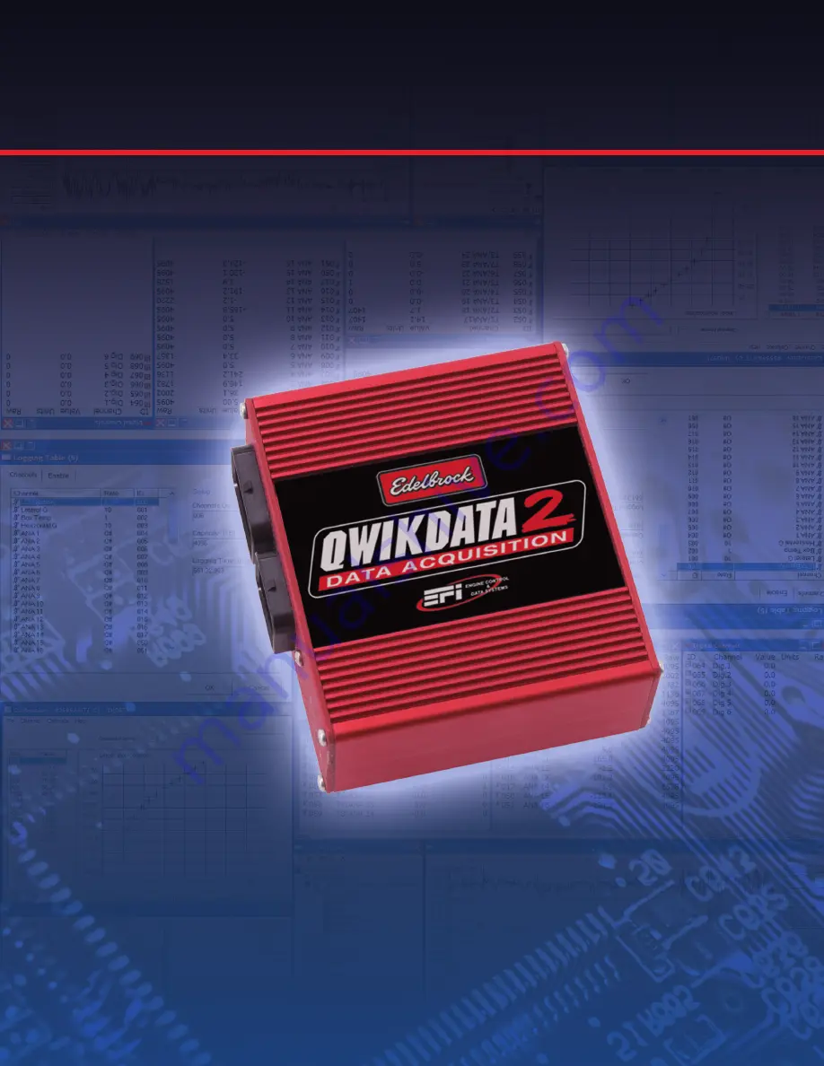
Edelbrock QwikData 2
Quick Start Guide

This QwikData 2 QwikStart guide is a condensed installation manual, outlining the basic setup functions to get your  
data acquisition system up and running.

For more detailed information and to better familiarize yourself with the power of QwikData 2 Data Logger System,  
please review the QwikData 2 Installation Manual and the Help Menu included in your software.

#63-91270QS

Summary of Contents for QwikData 2

Page 1: ...outlining the basic setup functions to get your data acquisition system up and running For more detailed information and to better familiarize yourself with the power of QwikData 2 Data Logger System...

Page 2: ...Setup 15 Step 7 Logger Set up 15 Logging Table Enable Conditions 16 Logging Table Channel Setup 17 USB COMMUNICATION 17 Step 8 Open the Comms Display Window 18 Step 9 Sending a Config to the LCU 19 St...

Page 3: ...t from current experienced users as well as Edelbrock Tech Reps Step 1 Software Installation Included in the installation is a SAMPLE DAT logger data file to help you familiarize yourself with the man...

Page 4: ...er up your Logger and connect to your Laptop with the USB cable When connected the logger hardware will be detected and the Found New Hardware wizard will open Follow the instructions to install the d...

Page 5: ...contain a Channel Logging Table Outing Information Channel Data and Channel Calibrations for up to 10 different cars A variety of tools are provided for setting up your data logger The setup screens h...

Page 6: ...ile NOTES The sample setup Car 01 is a blank setup for you to use as a template to create your own setup The setup file contains all your sensor channel calibrations names logging table etc The setup...

Page 7: ...k Register LCU s 2 Enter the LCU serial number and logger download path next to the Car setup you are working with 3 You can browse for a existing download path by clicking the button Select the new p...

Page 8: ...pe in any text Comments for the data set in Line 1 and Line 2 4 Enter track Name and Length Beacon Mask is reserved for options in future software releases 5 Click OK to save changes Notes The Outing...

Page 9: ...ation 1 Importing Calibrations The simplest most direct procedure for creating sensor calibrations is to import calibrations from a list of sensors organized by part number and accessed with the Impor...

Page 10: ...s for the selected channel Fig 3 Fig 3 5 Select Name and enter a name for the channel 6 Select Units and enter the units that you want the sensor data displayed in psi inHg Deg F etc 7 Select Graphics...

Page 11: ...edit Channel Parameters before creating calibrations Un named channels will be listed as LCU location or ANA 1 From the menu bar under Channels select Edit Calibrations Ctrl C this will open the calib...

Page 12: ...ed by part number or description and are available in various ranges and units 6 Double Click on a sensor name to select Fig 3 Fig 3 The calibration window will reopen with the selected calibration ap...

Page 13: ...alibration window and select the channel you want to calibrate Fig 1 Fig 1 2 On the calibration window menu under Channel select Manual ADC Count a check should appear 3 On the Calibration window Menu...

Page 14: ...hannel reading in the status bar is active showing the current output from the selected sensor and can be used to monitor the response of the sensor as it moves The lower right corner of the calibrati...

Page 15: ...a trigger wheel or flying magnet enter number of magnets or Teeth on trigger wheel The logger calculates distance and speed from the number of pulses received from the wheelspeed sensors and the tire...

Page 16: ...s that define when Data Logging starts and stops Data Logging will start when either of the start conditions are met but will only stop when both stop conditions are met This prevents logging unwanted...

Page 17: ...y and has a maximum through put of samples which dictates the logging rates for channels If you choose to log channels at a high rate you will reduce the total number of channels that you can log If a...

Page 18: ...to display channel data Once a screen format has been defined it can be saved to disk Step 8 Open the Comms Display Window Use this function to open the sample Comms display window included with your...

Page 19: ...ware Toolbar For details regarding how to Zero Analog channels see Zero Channels in the USB Communication section of the QwikData 2 Manual or from Help on your QwikData 2 Software Toolbar Step 9 Sendi...

Page 20: ...connect the USB cable between your laptop and LCU Verify communication is ON LINE in lower right corner of screen 1 On the Logger menu click Download A progress bar will briefly display indicating do...

Page 21: ...setup and make changes to improve vehicle performance Displayed below is some data from the Sample Data file included with the software The three data channels are tiled on the display To view the op...

Page 22: ...d folder where the Outing is located Downloaded Data File location was designated when you registered your LCU and set the download path in the Step 4 3 Click on the outing to read the file details an...

Page 23: ...the Outing to read the file details and comments 4 Double click the Outing or click OK to select it Notes To open a file you ve used recently you can use the Recent File menu list You can use the Add...

Page 24: ...t time The scale for the current channel is displayed on the left axis and additional channel information is displayed at the top of the graph Select the Add Channels Icon from the menu bar to display...

Page 25: ...der plotted against distance The scale for the current channel is displayed on the left axis and additional channel information is displayed at the top of the graph Select the Add Channels Icon from t...

Page 26: ...sary to move the Analog Signal or Digital Signal wires in the LCU connector The Sensor power and ground wires are all common To release the pins in the LCU Connector simply depress the single white re...

Page 27: ...26 Getting Started Edelbrock QwikData 2 Suggested Harness Routing...

Page 28: ...27 Getting Started Edelbrock QwikData 2 91290 Basic Analog Harness Details...

Page 29: ...28 Getting Started Edelbrock QwikData 2 91290 Basic Harness Schematic...

Page 30: ...ALOG 11 0014 28 N C 12 BROWN ANALOG 12 0015 29 N C 13 LT BLU FREQ 1 0064 TACH INPUT 30 N C 14 DK GRN FREQ 2 0065 31 N C 15 N C FREQ 5 0068 LOW RESOLUTION 32 N C 16 BROWN SW 3 33 N C 17 PNK BLK 12V SWI...

Page 31: ...30 Getting Started Edelbrock QwikData 2 91294 Advanced Thermocouple Harness Details...

Page 32: ...31 Getting Started Edelbrock QwikData 2 91294 Advanced Thermocouple Harness Schematic...

Page 33: ...G 7 9 YEL K TYPE 3 0054 22 RED K TYPE NEG 8 10 YEL K TYPE 4 0055 23 BLK K TYPE SHIELDS GRND 11 YEL K TYPE 5 0056 24 N C 12 YEL K TYPE 6 0057 25 DK GRN SWITCHED OUT 2 13 YEL K TYPE 7 0058 26 N C FREQ 6...

Page 34: ...33 Getting Started Edelbrock QwikData 2 91291 Advanced Analog Harness Details...

Page 35: ...34 Getting Started Edelbrock QwikData 2 91291 Advanced Analog Harness Schematic...

Page 36: ...C 9 DK BLU ANALOG 19 I D0054 22 N C 10 DK GRN WHT ANALOG 20 I D0055 23 N C 11 VLT ANALOG 21 I D0056 24 N C 12 TAN WHT ANALOG 22 I D0057 25 DK GRN SWITCHED OUT 2 13 WHT BRN ANALOG 23 I D0058 26 N C FR...

Page 37: ...hanges have been made 5 Verify Logging Table settings channels for logging channel sample rates and enable criteria 6 Update Outing Data file with driver and comments information 7 Update Setup sheet...

Page 38: ...updates and free downloads please see the Edelbrock web site and QwikData 2 Support Forum Edelbrock Toll Free Tech Line 800 416 8628 7am 5pm PST Monday Friday Web site Edelbrock com Automotive Data Ac...

Page 39: ...38 Getting Started Edelbrock QwikData 2 User Notes...

Page 40: ...h Line 1 800 416 8628 from 7am 5pm PST Monday Friday Headquarters 1 310 781 2222 from 8am 5pm PST Monday Friday Tech support QD edelbrock com DATA ACQUISITION www edelbrock com Edelbrock Corporation T...

Reviews: