background image


268

CC


268

Center Console

OWNER ASSISTANCE

MANUAL

Revised 2014

Summary of Contents for 268 Center Console

Page 1: ...268CC 268 Center Console OWNER ASSISTANCE MANUAL Revised 2014...

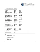
Page 2: ...RSON CAPACITY 12 PERSON WEIGHT 1980lbs 900kg FUEL CAPACITY 205gal 776 01L TRANSOM HEIGHT Twin 25 MAX POWER 500hp 375kw COCKPIT DEPTH 28 71cm COCKPIT AREA 92sq ft 8 5m APPROX LENGTH ON TRAILER 33 10m B...

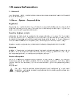
Page 3: ...boat large or small We believe you ll have many years of enjoyment from your new EdgeWater and thank you for entrusting your leisure time to one of our fine products This manual has been assembled to...

Page 4: ...ddress City State Zip Phone Fax Purchase Date Engine Make Model Delivery Date Engine Serial Hull Number DMA Ignition Key EdgeWater Power Boats LLC reserves the right to make alterations in the standar...

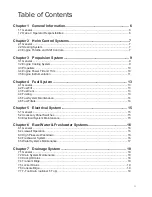
Page 5: ...1 General 13 4 2 Fuel Fill 13 4 3 Fuel Vent 13 4 4 Fueling 13 4 5 Fuel System Maintenance 14 4 6 Fuel Filters 14 Chapter 5 Electrical System 15 5 1 General 15 5 2 Accessory Panel Switches 15 5 3 Elec...

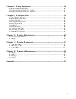
Page 6: ...9 4 Towing or Being Towed 25 9 5 Stopping the Boat 25 9 6 Docking 26 9 7 After Operation 26 9 8 Trailering Your Boat 26 9 9 Launching Your Boat 27 9 10 Retrieving Your Boat 27 Chapter 10 Routine Maint...

Page 7: ...e of more than 500 or if the boat is completely lost a formal report must be made within 10 days Questions regarding accidents may be directed to the Boating Safety Hotline 800 368 5647 Education Whet...

Page 8: ...d to wander slightly back and forth Keeping the wheel in the center without overcompensating for the slight wandering will prevent over steering and reduce the tendency to wander Steering System Maint...

Page 9: ...e the engine remains running The operator should always wear the engine stop switch lanyard while the boat is in motion Pulling the lanyard from the control will stop the engine If the engine will not...

Page 10: ...n accordance with the manufacturer s recommendations If the boat is to be kept in saltwater for an extended period electrolysis and marine growth can become a problem When leaving your boat in salt wa...

Page 11: ...get shorter engine life and poorer performance than your boat and motor were designed to provide If your boat came from the factory with a propeller selected by EdgeWater it should already be optimiz...

Page 12: ...ot tube These gauges should only be used as indicators of approximate speed and not used as absolute speed indicators NOTE All Yamaha speedometers utilize a pitot tube In the event that erroneous spee...

Page 13: ...ing If an engine alarm sounds shut down the engine until the source of the problem is determined Compass The compass assists in determining your location by indicating your position relative to magnet...

Page 14: ...4 2 Fuel Fill The fuel fill cap is located on the port side and is labeled GAS The fill is opened by turning it counterclockwise and closed by turning the cap clockwise Tighten the cap until it is snu...

Page 15: ...ents are found to be cracked they should be replaced at once If you use your boat infrequently or do not use it for an extended period of time a fuel conditioner should be added to a full tank of fuel...

Page 16: ...C is equipped with three batteries as standard designated PORT ENGINE STBD ENGINE and HOUSE with all connected to a battery isolator The selector switches provide isolation for each battery and also p...

Page 17: ...deck access doors and a washdown fitting to attach a hose The pump is controlled by the washdown switch on the control panel The diaphragm pump is fed through the same thru hull and high speed pickup...

Page 18: ...tem operates properly Periodically spray pumps with a protective silicone solvent to reduce corrosion Periodically check in line filter to remove any collected debris Fishboxes and livewells should be...

Page 19: ...automatic bilge pump are located The bilge pump is designed with an internal float so that it automatically turns on if the water in the sump rises or it may also be activated by a momentary switch o...

Page 20: ...pump will automatically turn on and drain the sump 7 7 T Top Drain optional T Top There are small holes drilled into the bottom of the T top to facilitate the removal of any water that might inadvert...

Page 21: ...ting Safety Hotline at 1 800 368 5647 or 1 202 267 1070 You should as part of routine boat maintenance check to make sure your extinguisher is still operable Never discharge your fire extinguisher to...

Page 22: ...fire extinguishers are in good working order It is advisable to carry jackets or foul weather gear in the event of adverse weather conditions Your EdgeWater 268CC is equipped with a maximum capacity...

Page 23: ...the first time make sure you follow the engine manufacturer s break in recommendations This will assure proper break in and reduce the possibility of engine problems 9 2 Basic Rules of the Road The fo...

Page 24: ...to bring it to plane briskly then back down to the cruising speed of your choice based on the sea conditions and your planned activity After coming on plane raise the trim to a point where the engine...

Page 25: ...also tow the disabled vessel from as close to amidships as possible This reduces the tendency to yaw If possible the towing boat should use a bridle attached to the two stern ski tow eyes The vessel...

Page 26: ...itch in the off position Remember the bilge pump will operate properly even with the battery switches turned off On a comforting note your EdgeWater 268CC is fully self bailing and unsinkable Proper p...

Page 27: ...ring launching Make sure the engine battery switches are in the on positions and the boat key is in the ignition Remove any tie down straps If someone is with you hand them the free end ofthe bow line...

Page 28: ...e grime If the boat is to be kept in freshwater or saltwater for an extended period a proper barrier coat and bottom paint must be applied to prevent possible Gel Coat blistering Do not wax non skid a...

Page 29: ...he water for extended periods Do not crank the engine without water running Water acts as a coolant and also a lubricant for the water pump Do not rev the engine when flushing idle speed is sufficient...

Page 30: ...ortant for seaworthiness and fuel consumption A hull is usually more efficient when running level and with the bow 3 to 5 degrees above level Tabs can also be useful when running into a heavy wind tha...

Page 31: ...ver Outside under a boat cover Boat cover should allow ample ventilation and be removed periodically to allow moisture to dissipate avoiding mildew growth and staining 12 4 Trailer Check the wheel bea...

Page 32: ...31 Appendix 268CC...

Page 33: ...34...

Page 34: ...35 Hydraulic Steering System...

Page 35: ...36...

Page 36: ...37...

Page 37: ...38...

Page 38: ...39...

Page 39: ...40...

Page 40: ...41...

Page 41: ...pass to test a location There are two brass rods near the bottom of the compass which rotate 360 degrees the slotted ends may be all that is visible These compensation rods are used to correct your co...

Page 42: ...s can develop when the boat heels over and pitching occurs simultaneously There is also potential error from the built in compensator magnets if the compass is not mounted vertically HD 74 HD 75 SS 11...

Page 43: ...ea with the compass in its intended position but not finally secured see Mounting the Compass obtain the Loran GPS bearing to a fixed aid or landmark that is within 10 o of a North South line Step Two...

Page 44: ...arge This warranty does not cover breakage through accident or misuse Replacement or repair will be made if the instrument is returned prepaid to a Ritchie Service Station or directly to E S Ritchie S...

Page 45: ...fit your needs TLM SXL TLM S Standard Mount TLM U Adapts to Specific Transom Angles PLM Platform Ladder Mount RM S Retro fit Mount Slotted Easy access both in and out of the water Every ladder comes w...

Page 46: ...Works Simply pull yourself to the boat Just swing it up to store in the mount Every ladder comes with storage clips for easy stowage NOW SWINGS ANP 1205 2 3 4 Step Models Unparalleled ease of access w...

Page 47: ...WE MAKE THE BEST BOATS BETTER The world leader in trim tab trolling motor and hatch lift innovation OWNER S MANUAL Featuring NEW waterproof Deutsch connectors...

Page 48: ...tro polished solid 316 stainless steel billet end for Extreme Duty Heavy Duty and High Performance applications The entire Lenco Actuator is fully submersible maintenance free and sealed for life Dual...

Page 49: ...rved 2007 Lenco Marine Inc CONGRATULATIONS You have just purchased the finest performance trim tab system in the world Welcome to the future Lenco Trim Tabs make the single most important difference i...

Page 50: ...ing Diagram 124SSR 13 Flybridge Wiring Diagram 14 Switch Wiring Diagram Dual Actuators 15 Warranty 11 Switch Options Upgrades 16 Optional Switches 16 Operation 17 Bennett Marine RetroFit Kit Installat...

Page 51: ...he left side of the switch controls the starboard tab The right side of the switch controls the port tab The system is set up this way to minimize the guesswork while underway To lower the starboard b...

Page 52: ...in the stern of the boat and keeps the bow down As you throttle up and speed increases raise tabs by pressing BOW UP on both sides Uneven Load If one side of the boat is higher than the other while ru...

Page 53: ...lution Sequence 1 Inspect fuse at fuse panel Replace if necessary 2 Verify that all connections at switch control box are tight and in place 3 Make sure that switch assembly has a solid ground 4 If th...

Page 54: ...use any other type of alloy Mount the trim tab hinge to the transom using provided 14 x 1 1 4 3 17 cm stainless steel metal screws We recommend using 3M 5200 adhesive caulking to bed the hinge and scr...

Page 55: ...adhesive caulking will seal the holes when installed All supplied screws and fasteners are stainless steel Do not use any other type of alloy 4 Warning With some installations fuel water tanks and oro...

Page 56: ...able with a clamshell vent sealed with 3M 5200 for a waterproof and nished effect Assemble actuator connector ends as instructed in Actuator Deutsch Connector Instructions insert card provided 5 At th...

Page 57: ...r return quickly Should time restraints prohibit you from sending in the merchandise rst or you need an immediate replacement you will be required to secure the replacement part with a credit card pri...

Page 58: ...27 Note In all cases make sure control box is mounted with wires facing down toward deck 15069 001 124SSR This product must be wired exactly as shown above Failure to wire the trim tab retractor as s...

Page 59: ...01 123SC Note In all cases make sure control box is mounted with wires facing down toward deck This product must be wired exactly as shown above Failure to wire the trim tab retractor as shown will ca...

Page 60: ...te Page 27 Note In all cases make sure control box is mounted with wires facing down toward deck This product must be wired exactly as shown above Failure to wire the trim tab retractor as shown will...

Page 61: ...ll cases make sure control box is mounted with wires facing down toward deck 15071 001 123DRSC This product must be wired exactly as shown above Failure to wire the trim tab retractor as shown will ca...

Page 62: ...of maintenance free easy to install tactile switches Lenco switches feature 1 Self Check feature at power up 2 Self contained sealed keypad 3 Self contained sealed control box 4 Fade smudge proof lase...

Page 63: ...ttom to top to indicate self test at power up If there is a problem with an actuator connection the L E D displays shows every other light red ON at the side that has the problem After self test is co...

Page 64: ...upper bracket and gland seal see Fig 1 You will need to clean mounting surfaces on the transom with a cleaning solvent such as mineral spirits or alcohol to remove all oils and dirt before final moun...

Page 65: ...hrough the second washer and other side of the bracket Replace the bracket screw removed in step 3 This will lock the pin in place and prevent it from falling out 7 Now you will need to hook up the Le...

Page 66: ...h from the previous system Simply reconnect it as per the wiring diagram 3 Test the trim tabs for proper operation Remember that the right switch controls the left trim tab and the left controls the r...

Page 67: ...g holes when upgrading from trim tabs to Troll n Tabs the trim tabs have to have been mounted with the hinges at least 3 8 95 cm from transom bottom as recommended in Lenco installation instructions S...

Page 68: ...101 Actuator IS USED IN ALL 44 Standard kits 101 Actuator 21 4 stroke Overall length tip to tip 121 8 inches Part 15054 001 101 2 12 volt W g CABLE 15061 001 101 3 24 volt W g CABLE 127 8 32 70 cm 121...

Page 69: ...y Should time restraints prohibit you from sending in the merchandise rst or you need an immediate replacement you will be required to secure the replacement part with a credit card prior to shipment...

Page 70: ...E TO MAKE ACCURATE MEASURE COULD CAUSE damage to hatch lift or the hatch itself s ENCO HATCH LIFTS ARE FULLY SUBMERSIBLE AND WILL not drift s ENCO HATCH LIFTS ARE OFFERED IN BOTH AND 24 volts OPERATIO...

Page 71: ...be lifted 2 Determine the angle of the hatch lift mount Do not exceed 45 degrees from center 3 Mount the hatch lift on the desired location as per the above instructions Important It may be necessary...

Page 72: ...NCLUDES TWO 8 ACTUATORS 24 X 8 3 FOUR 8 ACTUATORS 24 X 8 3 24 X 8 3 ON TWO GAUGE electro polished stainless steel blades w transom back plates and super duty hinge with 3 8 95 cm hinge pin s CTUATOR E...

Page 73: ...08 cm hole for Switch Key Pads Tactile Switch Connection Mount control box within 30 76 2 of keypad Control box wire harness is 30 76 2 length High Performance Tabs Single Dual Actuator s IGH PERFORM...

Page 74: ...ENCO ARINE NC UNICIPAL OURT s 3TUART LORIDA s FAX s WWW LENCOMARINE COM DON T WORRY we ve got your back 8 07...

Page 75: ...water tank open all faucets then turn pump switch on Water will begin to flow When the water is free of air turn faucets off Remember you are filling the water heater and the toilet and shower lines W...

Page 76: ...o the red lead on the pump housing located pressure switch STEP 5 Connect the black lead from the pump to the ground or negative power side of the vessel STEP 6 Turn the system off when not in use for...

Page 77: ...sed with Jabsco pumps Follow manufacturer s recommendations Refer to boat or equipment manufacturer s instructions for their specific winterizing and drainage procedures Do not use automotive antifree...

Page 78: ...53 7311 Fax 39 039 666 307 THE PRODUCTS DESCRIBED HEREIN ARE SUBJECT TO THE JABSCO THREE YEAR LIMITED WARRANTY WHICH IS AVAILABLE FOR YOUR INSPECTION UPON REQUEST Copyright 2005 ITT Industries Printed...

Page 79: ...ted motor for extra protection in harsh environment applications SPECIFICATIONS Pump Body Glass Filled Polypropylene Pump Design Multi Chamber Diaphragm Suction Lift Self Priming to 10 ft 3 m Ports 1...

Page 80: ...ump off when not used for extended periods or when the tank is empty The electrical circuit should be protected with an over current protection device in the positive lead See chart for proper size Th...

Page 81: ...ws securely 18 in lbs torque Also the Outer Pistons 3 C must be aligned with alignment slots on Cam Assembly 4 B making sure screw holes align in cam assembly otherwise diaphragm will leak Cam Bearing...

Page 82: ...efective motor PUMP FAILS TO TURN OFF AFTER ALL FIXTURES ARE CLOSED Empty water tank Punctured pump diaphragm water leak Discharge line leak Defective pressure switch Insufficient voltage to pump Debr...

Page 83: ...Instruction Manual Ultima Bilge 600GPH 800GPH 1000GPH 1250GPH Read and understand this manual prior to operating or servicing this product IB 123 01 0912...

Page 84: ...ITS INCIDENTAL OR CONSEQUENTIAL COSTS EXPENSES OR DAMAGES THE LIMITATION ON LIABILITY FOR LOST PROFITS INCIDENTAL OR CONSEQUENTIAL COST EXPENSES OR DAMAGES SHALL SURVIVE ANY FAILURE OF ESSENTIAL PURPO...

Page 85: ...ndning av en felaktig s kring kan leda till personskador egendomsskador och brandfara Installation av Ultima Bilge Varning Vid installation av Ultima Bilge s kerst ll att pumpen r fri fr n alla hinder...

Page 86: ...mningen r avg rande f r pumpens till mpning re kommenderas det att inte anv nda back ventilen Dessutom vid vinterrustning av din b t ta bort backventilen f r att undvika isbildning och eller f rs mrin...

Page 87: ...ns och vrid pumphjulets skydd medurs och dra rakt ut Avl gsna och reng r pumphjulet och pumpen fr n allt skr p som har samlats S kerst ll att ven reng ra eventuellt skr p som samlats p ltret Efter at...

Page 88: ...ill den negativa bat teriterminalen F r att vidarekoppla driften manuellt anslut den bruna ledningen fr n pum pen till panelomkopplaren F r automatdrift anslut den bruna ledningen med den vita sp rnin...

Page 89: ...ing the wrong fuse can lead to personal injury property damage and re hazard Installing the Ultima Bilge Pump Caution When installing the Ultima Bilge Pump make sure that pump is clear of all obstacle...

Page 90: ...will reduce the ow of the pump If ow is critical to the application of the pump it is recommended that the check valve not be used Also when winterizing your boat re move the check valve to avoid ice...

Page 91: ...o impeller guards ns and rotate im peller guard clockwise and pull straight out Remove and clean the impeller and pump from all debris that has accumu lated Make sure to clean any debris that has accu...

Page 92: ...nd wire to the negative terminal of the battery For manual over ride operation connect the brown wire from the pump to the switch panel For automatic operation connect the brown wire with white tracer...

Page 93: ...on falschen Sicherungen kann zu Personensch den Materialsch den und Brandgefahr f hren Installation der Ultima Lenzpumpe Vorsicht Stellen Sie bei der Installation der Ultima Lenzpumpe sicher dass es k...

Page 94: ...s ist aus Nitril das ausschlie lich f r Wasseranwendungen eingesetzt werden soll Au erdem verkleinert das R ckschlagventil den Pumpendurch uss Falls der Durch uss bei der Einsetzung der Pumpe wichtig...

Page 95: ...im Uhrzeigersinn und ziehen Sie es aufrecht heraus Entfernen und reinigen Sie das Antriebsrad und die Pumpe von al len angesammelten Fremdk rpern Entfernen Sie alle angesammelten Fremdk rper auch vom...

Page 96: ...erie angeschlossen F r manuellen Betrieb wird der braune Leiter von der Pumpe an die Schalttafel angeschlossen F r automatischen Betrieb wird der braune Leiter mit wei er Kennzeichnung an die Schaltta...

Page 97: ...un fusible erron peut pro voquer des blessures des d g ts mat riels ou un risque d incendie Installation de la pompe de fond de cale Ultima Bilge Attention Lors de l installation de la pompe de fond...

Page 98: ...le ment De m me le clapet de anti retour dimi nuera le ux de la pompe Si le ux est crit re critique dans l application de la pompe il est recommand de ne pas utiliser le clapet de anti retour Egalemen...

Page 99: ...pot dans le sens des aiguilles d une montre et tirez directement vers vous Enlevez tous les d bris accumul s et nettoyez la turbine Assurez vous de nettoyer absolu ment tous les d bris qui se sont acc...

Page 100: ...rne n gative de la batterie Pour un fonctionnement manuel raccordez le l brun de la pompe sur le panneau d interrupteur Pour un fonctionnement automatique raccordez le l brun avec une ligne blanche au...

Page 101: ...la gasolina el gasoil o l quidos in amables Aseg rese de usar el tama o de fusible apropiado recomendado por el modelo de su bomba Usar el fusible equivocado pue de provocar da os personales da os a l...

Page 102: ...forzada con una pared interior suave NOTA La v lvula de control suministrada con su bomba de desfonde Ultima se usa para evitar que el agua uya hacia atr s La utilizaci n de la v lvula de control requ...

Page 103: ...ia abajo las leng etas de cierre laterales en el cuerpo de la bomba y saque la bomba del ltro Para limpiar el propulsor agarre las aletas de defensa del propulsor y gire la seguridad del propulsor com...

Page 104: ...de la bater a Para su funcionamiento manual conecte el cable marr n desde la bomba hasta el panel de interruptores Para funcionamiento autom tico conecte el cable marr n con rastreador blanco al pane...

Page 105: ...pu causare danni a persone o cose e pericolo di incendio Installazione della pompa di sentina Ultima Attenzione Durante l installazione della pom pa di sentina Ultima assicuratevi che la pompa sia lib...

Page 106: ...l usso del la pompa Pertanto se il usso cruciale per l utilizzo della pompa si raccomanda di non impiegare la valvola di controllo Inol tre durante la predisposizione dell imbar cazione per il funzion...

Page 107: ...pulire il girante afferrate le alette della custodia ruotate la custodia in senso orario e tirate forte Quindi rimuovete il girante e pulite gi rante e pompa da tutti i detriti che si sono accumulati...

Page 108: ...a batteria Per operazioni manuali override connettere il cavo marrone dalla pompa al pannello inter ruttore Per operazioni automatiche connettere il cavo marrone con il conduttore bianco al pan nello...

Page 109: ...mble the product and recycle the parts material Entsorgung Recycling Nach Lebensdauerende entsorgen Sie die Pumpe nach den rtlichen Vorschriften Nach M glichkeit demontieren Sie Teile der Pumpe um sie...

Page 110: ...owie Ma angaben wie sie in dieser Mitteilung beschrieben sind sind nur zur Information Alle Angaben sind unverbindlich es sei denn sie wurden schriftlich best tigt Pour plus d information sur nos succ...

Page 111: ...Instruction Manual Submersible Bilge Pump L1600 L2200 L4000 Read and understand this manual prior to operating or servicing this product IB 106 03 0911...

Page 112: ......

Page 113: ...rnationales nos approbations nos certi cations et nos repr sentants locaux veuillez consulter notre site Internet au www johnson pump com SPX Corporation se r serve le droit d incorporer nos plus r ce...

Page 114: ...alt 2 Kapacitet fritt utlopp 13 6V 27V 100 l min 1 600 GPH 130 l min 2 060 GPH 258 l min 4 100 GPH 12V 24V 92 l min 1 450 GPH 120 l min 1 900 GPH 252 l min 4 000 GPH Kapacitet lyfth jd 1m 13 6V 27V 9...

Page 115: ...pumpen p ltret och se till att b da l stapparna sn pper fast 6 V lj en plats d r vattnet ska pumpas verbord s h gt som m jligt ver vattenlinjen och s n ra pumpen som m jligt Installera en 28 mm 1 8 L...

Page 116: ...min 1 600 GPH 130 l min 2 060 GPH 258 l min 4 100 GPH 12V 24V 92 l min 1 450 GPH 120 l min 1 900 GPH 252 l min 4 000 GPH Capacity 1m head 13 6V 27V 98 l min 1 550 GPH 120 l min 1 900 GPH 196 l min 3 1...

Page 117: ...er to the wooden block 5 Mount the pump on the strainer so that both locktabs snaps into place 6 Select a point where the bilge water is to be pumped overboard as high as possible above the water line...

Page 118: ...chdurchmesser 1 8 1 8 oder 1 1 oder 2 Leistung bei geradem Auslauf 13 6V 27V 100 l min 1 600 GPH 130 l min 2 060 GPH 258 l min 4 100 GPH 12V 24V 92 l min 1 450 GPH 120 l min 1 900 GPH 252 l min 4 000...

Page 119: ...gkorb aufsetzen und daf r sorgen da die beiden Verriegelungszapfen fest einrast 6 Suchen Sie eine g nstige Stelle f r den Borddurchla aus Dieser sollte m glichst hoch ber der Wasserlinie und dennoch i...

Page 120: ...u 38mm 38mm ou 50mm D bit refoulement libre 13 6V 27V 100 l min 1 600 GPH 130 l min 2 060 GPH 258 l min 4 100 GPH 12V 24V 92 l min 1 450 GPH 120 l min 1 900 GPH 252 l min 4 000 GPH D bit refoulement 1...

Page 121: ...mpe sur le ltre et s assurer que les deux verrous sont bien enclench s 6 Choisir un endroit par lequel les eaux de cale seront pomp es et vacu es aussi haut que possible au dessus de la ligne d eau et...

Page 122: ...dal salida libre 13 6V 27V 100 l min 1 600 GPH 130 l min 2 060 GPH 258 l min 4 100 GPH 12V 24V 92 l min 1 450 GPH 120 l min 1 900 GPH 252 l min 4 000 GPH Caudal a 1m altura 13 6V 27V 98 l min 1 550 GP...

Page 123: ...e madera a la que se jar el ltro 5 Colocar la bomba en el ltro y asegurarse que los dos pernos de cierre quedan bien encajados 6 Elegir un punto en que la salida del agua est a la mayor distancia posi...

Page 124: ...L4000 Sezione tubo 1 8 1 8 o 1 1 o 2 Portata massima 13 6V 27V 100 l min 1 600 GPH 130 l min 2 060 GPH 258 l min 4 100 GPH 12V 24V 92 l min 1 450 GPH 120 l min 1 900 GPH 252 l min 4 000 GPH Portata a...

Page 125: ...dr prima apposto un basamento in legno e su questo ssato il ltro 5 Montare la pompa sul ltro accertandosi che entrambi i perni scattino in posizione di bloccaggio 6 Scegliere il punto da cui l acqua d...

Page 126: ...med str mbrytarpanel Electrical installation with panel Elektrische Installation mit Schalttafel Installation electrique avec panneau Instalaci n el ctrica con panel Installazione elettrica con panne...

Page 127: ...z Pumpe Noir pompe Negro bomba Nero pompa G Brun Brown Braun Marron Marr n Marrone H Brun Ultima Brown Ultima Braun Ultima Marron Ultima Marr n Ultima Marrone Ultima Elektrisk installation med str mbr...

Page 128: ...rytarpanel med elektronisk niv str mbrytare Electrical installation without panel with electronic oat switch Elektrische Installation ohne Schalttafel mit elektronischem Schwimmerschalter Installation...

Page 129: ......

Page 130: ...approvals certi cations and local representatives please visit www johnson pump com SPX Corporation reserves the right to incorporate our latest design and material changes without notice or obligati...

Page 131: ...50890 Waste Pump Pompe d eaux us es F kalienpumpe Pompa di scarico Afvoerpomp T mningspump Bomba para desechos...

Page 132: ...angles of heel or trim Waste Pump Robust Single Diaphragm Design Features G Flexible installation G No filter required G Compact and simple design G Self priming to 3m 10ft G 12v and 24v variants G Dr...

Page 133: ...n inside back cover 1 Push down on clip and remove end cover 2 Internal bolt heads now exposed 3 Undo all four mounting bolts 4 Remove bolts and grasp motor unit firmly 5 Rotate pump head to desired p...

Page 134: ...Courbe de performances AVERTISSEMENT on ne doit pas utiliser une pompe Jabsco avec de l essence des produits p troliers ou tout produit ayant un point d clair inf rieur 37 C faute de quoi on s expose...

Page 135: ...1 Appuyer sur la pince et enlever le couvercle 2 Les t tes de boulon internes sont maintenant expos es 3 D faire les quatre boulons de montage 4 Enlever les boulons et tenir fermement l ensemble du m...

Page 136: ...TUNG Jabsco Pumpen nicht f r Benzin Erd lprodukte oder andere Produkte mit einem Flammpunkt unter 37 C benutzen da sonst Explosions oder Lebensgefahr besteht Betrieb Der Gleichstrommotor ist f r den K...

Page 137: ...SICHERUNG AUSLASS FFNUNG EINLASS FFNUNG Schaltplan BATTERIE Max Amp Max Kabelquerschnitt Modell Nr Spannung Stroment Sicherun Max nahme gsgr e AWG mm 2 L nge 50890 1000 12V 8A 10A 14 2 5 4 5m 15ft 14...

Page 138: ...BSEN 50081 electromagnetische compatibiliteit Prestatiekromme WAARSCHUWING Nooit een Jabsco pomp gebruiken voor benzine aardolieproducten of enig product met een vlampunt onder 37 C daar dit explosie...

Page 139: ...beeldingen aan binnenzijde van achteromslag 1 Clip induwen en einddeksel afnemen 2 Inwendige boutkoppen nu zichtbaar 3 Alle vier montagebouten losmaken 4 Bouten uitnemen en motordeel stevig vastgrijpe...

Page 140: ...VERTENZA NON usare le pompe Jabsco con benzina petrolio o altri prodotti con punto di infiammabilit inferiore ai 37 C in quanto ci potrebbe provocare esplosioni o morte Funzionamento Il motore a corre...

Page 141: ...raccarichi FILO ARANCIONE FILO NERO FUSIBILE APERTURA DI USCITA APERTUR A DI ENTRATA Schema dei collegamenti BATTERIA Consumo Dimensioni Dimensioni fili N modello Tensione massimo Massime Lunghezza fu...

Page 142: ...ikation G St mmer med BSEN 50081 elektromagnetisk l mplighet Prestationskurva VARNING Anv nd inte n gon Jabsco pump till bensin petroleumprodukter eller produkter med en flampunkt under 37 C d det kan...

Page 143: ...l mman och tag bort ndplattan 2 De inre bulthuvudena fril ggs d 3 Lossa alla fyra monteringsbultarna 4 Tag bort bultarna och grip stadigt tag i motorn 5 Vrid pumphuvudet till nskad position 6 Exempel...

Page 144: ...ciones ADVERTENCIA No utilize ninguna bomba Jabsco para gasolina productos de petr leo ni para ning n producto con un punto de inflamaci n por debajo de 37 C ya que ello podr a causar explosiones o mu...

Page 145: ...mpedir la corrosi n G Proteja el circuito con un fusible de intensidad nominal o disyuntor en el cable rojo positivo tan cerca de la fuente de potencia como sea posible G Conecte el cable negro del mo...

Page 146: ...8 Rotation of Ports 1 2 3 4 5 6 7 1 Rotation of Pump Head 2 3 4 5...

Page 147: ...te Pump Key Description Quantity in Kit 1 Bracket 2 Bush 3 Clamp Bottom 4 Clamp Top 5 Con Rod 6 Con Rod Plate 7 Cover 1 8 Diaphragm 1 9 Hex Head Screw 10 Hex Head Screw 4 11 Motor Assembly 12 Screw Re...

Page 148: ...ma 222 JAPAN Tel 81 0 45 475 8906 Fax 81 0 45 475 8908 Jabsco GmbH Oststra e 28 22844 Norderstedt GERMANY Tel 49 0 40 53 53 73 0 Fax 49 0 40 53 53 73 11 Jabsco Marine Italia S r l Via Tommaseo 6 20059...

Page 149: ...Instruction Manual UltimaSwitch 12 24 V Read and understand this manual prior to operating or servicing this product IB 116 02 0911...

Page 150: ...O 8846 1990 Electrical devices Protection against ignition of surrounding ammable gases Made in the USA Garantie 3 ans Garant a 3 a os Garanzia 3 anni Garanti 3 r Warranty 3 year Garantie 3 Jahren IND...

Page 151: ...epp kr vs Varning 1 Anslut en rads kring med r tt amperetal anges p pumpen 2 UltimaSwitch r konstruerad endast f r 12 VDC och 24 VDC drift Anv nd inga andra sp nningar anv nd inte AC eller AC DC omvan...

Page 152: ...nv ndning av sidopelarna och beakta samma monteringsanvisningar som n r du monterar UltimaSwitch i ett vertikalt l ge Montering 1 M rk ut styrh len i UltimaSwitch sockeln genom att anv nda UltimaSwitc...

Page 153: ...ltimaSwitch ledningen till den bruna pumpledningen 5 Den svarta pumpledningen till minus batterikl mman 6 2 v gsomkopplare p instrumentbr dan Auto On Funk tion Anslut brun brytarledning och brun plus...

Page 154: ...art minus ledning fr n pumpen leds alltid till jord Drift av UltimaSchwitch 1 Efter att installationen av UltimaSwitch r avslutad h ll tv ngrar ver de upph jda cirkelrunda omr dena p UltimaSwitch unde...

Page 155: ...gt att placera Ultima Switch p ett annat st lle Fels kning Pumpen aktiveras inte t POUSPMMFSB MFEOJOHBSOBT BOTMVUOJOHBS t POUSPMMFSB T LSJOHFO t POUSPMMFSB QVNQFO HFOPN BUU EJSFLULPQQMB EFO UJMM CBUUF...

Page 156: ...i VARNING Garantinblirogiltigomt tningarp produktenf rst rs om n gon elektrisk ledare kapas mer n 3 tum om elektriska skarvar s nks ned i vatten eller om produkten installeras i strid mot instruktione...

Page 157: ...Caution 1 Connect an inline fuse of the appropriate amperage speci ed on the pump 2 The UltimaSwitch is designed for 12 VDC and 24 VDC operation only Do not use any other voltages do not use AC or AC...

Page 158: ...the UltimaSwitch using the side posts and observing the same mounting instructions as you would installing the UltimaSwitch in a vertical position Mounting 1 Mark pilot holes in the base of the Ultima...

Page 159: ...nnect brown switch wire lead and brown positive pump wire lead to positive ON position of dash panel switch Connect brown with White Tracer switch wire lead to positive battery terminal in line fuse r...

Page 160: ...seconds If the wiring is correct the bilge pump will activate If you remove a nger from the top circle the pump should continue to be on After removal of both ngers the bilge pump will no longer run...

Page 161: ...e operation In case of malfunction make sure that the UltimaSwitch is clear of oating debris At all times keep all fuse and wire connections high and dry Warranty Your UltimaSwitch is covered by a thr...

Page 162: ...genpumpe ein Vorsicht 1 Schlie en Sie eine Inline Sicherung mit angemessener Strom st rke siehe Pumpe an 2 Der UltimaSwitch ist geeignet nur f r den 12 VDC und 24 VDC Betrieb Verwenden Sie keine ander...

Page 163: ...h SchalterandieSeitedesBoots montieren stellen Sie sicher dass Sie den UltimaSwitch Schalter mittels Seitenpfosten befestigen und dieselben Montageanwei sungen befolgen wie beim Anbau des UltimaSwitch...

Page 164: ...MFNNFO TPMMUF n TTJHFT TPMJFSCBOE WFSXFOEFU XFSEFO JF Montageanschl sse sollten sich ber dem h chsten Wasser stand be nden FS CSBVOF SBIU NJU XFJ FN FJDIOFS EFT 6MUJNB Switch Schalters sollte an den...

Page 165: ...en Sie den braunen SBIU NJU XFJ FO FJDIOFS EFT 4DIBMUFST BO EFO QPTJUJWFO On Stellung Draht des Bedienungsfeldschalters Inline Sicherung n tig 8 Dreiwege Bedienungsfeld Schalter EIN AUS Automatik betr...

Page 166: ...rahtung korrekt ist schaltet die Bilgenpumpe ein 8FOO 4JF ISFO JOHFS WPN PCFSFO SFJT FOUGFSOFO TPMMUF EJF Pumpe weiter eingeschaltet bleiben Nach dem Entfernen beider Finger schaltet die Pumpe nach ei...

Page 167: ...Im Falle von St rungen stellen Sie sicher dass der UltimaSwitch frei von Fremdk rpern ist Halten Sie die Sicherung und die Drahtanschl sse hoch und trocken Garantie Ihrem UltimaSwitch Schalter gilt e...

Page 168: ...saire Attention 1 Raccordez en ligne un fusible d un amp rage ad quat sp ci sur la pompe 2 L UltimaSwitch est con u pour ne fonctionner qu en 12 VDC et 24 VDC N utilisez aucune autre tension ne pas ut...

Page 169: ...Switch sur le c t du bateau assurez vous d installer l UltimaSwitch en utilisant les montants lat raux et en observant les m me instructions de montage comme si vous installiez l UltimaSwitch en posit...

Page 170: ...Le montage des rac cordements doit tre au dessus du niveau d eau le plus haut 3 Le l Brun avec le Marquage Blanc de l UltimaSwitch doit tre reli au l prot g par le fusible de la borne positive 4 Le l...

Page 171: ...eur la borne positive position Marche On du tableau de commande fusible en ligne n cessaire 8 Interrupteur trois voies du tableau de commande avec fonctionnement Marche Arr t Auto ON OFF Auto Opera ti...

Page 172: ...a tre activ e Si vous retirez un doigt du cercle du haut la pompe devrait continuer fonctionner Apr s avoir retir les deux doigts la pompe ne doit pas continuer fonctionner apr s un court temps de ret...

Page 173: ...ent sans aucun entretien En cas de mauvais fonctionnement assurez vous que l UltimaSwitch est libre de d bris ottants En tout temps maintenez les c bles et fusibles hors d eau et secs Garantie Votre U...

Page 174: ...que sea necesario ning n ajuste Peligro 1 Conecte un fusible de l nea entrante del voltaje apropiado especi cado en la bomba 2 El UltimaSwitch est dise ado para su operaci n con 12V DC y 24V DC solo N...

Page 175: ...t montando el UltimaSwitch a un lado de la embarca ci n aseg rese de que sujeta el UltimaSwitch usando los postes laterales y observando las mismas instrucciones de montaje que si montara el UltimaSwi...

Page 176: ...xiones de montaje deber an estar por encima del nivel m s alto del agua 3 El cable Trazador Marr n con Blanco UltimaSwitch se deber a jar al cable del fusible desde el terminal positivo 4 El cable de...

Page 177: ...sici n de Encendido del interruptor del panel se necesita un fusible con l nea de entrada 8 Interruptor de Panel de 3 V as de Arranque de Operaci n Apagado Encendido Auto Conecte el cable de plomo mar...

Page 178: ...ado es correcto la bomba de sentina se activar Si quita un dedo del c rculo superior la bomba deber a seguir encendida Despu s de quitar los dos dedos la bomba de sentina dejar de funcionar despu s de...

Page 179: ...antenimiento En caso de mal funcionamiento aseg rese de que el UltimaSwitch est limpio de basura otante Mantenga siempre todas las conexiones de cables y fusibles en alto y secos Garant a Su UltimaSwi...

Page 180: ...di una pompa a corrente continua da 24 V senza necessit di una ulteriore regolazione Attenzione 1 Collegate un fusibile in linea con amperaggio appropriato speci cato sulla pompa 2 L interruttore Ulti...

Page 181: ...rruttore 3 La parte inferiore dell interruttore UltimaSwitch pu essere posizionata al di sopra della base della pompa ma mai al di sotto NB Nel caso in cui montiate l interruttore UltimaSwitch sul lat...

Page 182: ...ia e l interruttore UltimaSwitch 2 I collegamenti dei cavi devono essere dotati di morsetti per manenti resistenti all acqua I morsetti devono essere rivestiti con adesivo liquido per materiale elettr...

Page 183: ...al conduttore del cavo marrone positivo della pompa Collegate il conduttore isolato del cavo marrone con tracciatura bianca dell interruttore al positivo posizione ON acceso dell interruttore del pan...

Page 184: ...pompa di sentina si attiva Togliendo il dito dal cerchio superiore la pompa dovrebbe continuare a funzio nare Togliendo entrambe le dita la pompa smette di funzio nare dopo breve tempo 2 Assicuratevi...

Page 185: ...l funzionamento assicuratevi che l interruttore sia libero da detriti galleggianti I fusibili ed i collegamenti elettrici devono sempre essere mantenuti asciutti ed in posizione elevata Garanzia Il vo...

Page 186: ...38 A B 50 mm C 20 mm...

Page 187: ...DC Versorgung Batterie Bater a Batteria Elektrisk installation med Johnson Pump panel Electrical installation with Johnson Pump Panel Elektrischer Anschluss mit Johnson Pump Schalttafel Sch ma de rac...

Page 188: ...d s Advertencia Estos cables ya van conectados Nota Bene Questi cavi sono gi collegati A B C Brun nr 2 Brown No 2 Braunes Nr 2 Marron No 2 Marr n No 2 Marrone No 2 Brun vit nr 1 Brown white No 1 Braun...

Page 189: ...terie Bater a Batteria C S kring Fuse Sicherung Fusible Fusible Fusibile Elektrisk intsallation utan panel Electrical installation without panel Elektrischer Anschluss ohne Schalttafel Sch ma de racco...

Page 190: ...r n Marrone Svart Black Schwarz Noir Negro Nero A B C Brun nr 2 Brown No 2 Braunes Nr 2 Marron No 2 Marr n No 2 Marrone No 2 Brun vit nr 1 Brown white No 1 Braunes weiss Nr 1 Marron blanc No 1 Marr n...

Page 191: ...ALTER THIS WARRANTY IN ANY WAY IN NO EVENT WILL JOHNSON PUMPS OF AMERICA BE LIABLE FOR MORE THAN THE SALES PRICE OF THE PRODUCT UNDER NO CIRCUMSTANCES WILL JOHNSON BE LIABLE FOR ANY LOST PROFITS INCI...

Page 192: ...pump marine processequipment spx com For more information about our worldwide locations approvals certi cations and local representatives please visit www johnson pump com SPX Corporation reserves the...

Page 193: ...PH Livewell Pump with Angled Pickup Tube 2 5 500 340 403 C 800 GPH Livewell Pump with Angled Pickup Tube 5 800 490 405 C 1000 GPH Livewell Pump with Angled Pickup Tube 6 1000 710 401STC 500 GPH Livewe...

Page 194: ...hreaded connections 3 Screw the pump into the seacock until it is hand tight Do not over tighten 4 If the pump is mounted horizontally the output must be pointed upward to allow air to vent KEEP SEACO...

Page 195: ...tighten 4 Slide hose sprayer assembly back through holder from above the deck and replace the 1 2 adapter 5 Connect to desired 1 2 NPT Male water source or valve Make sure rubber washer is in place in...

Page 196: ...ay be resolved by a SHURflo service center All returns are to be shipped with charges pre paid Package all returns carefully SHURflo will not be responsible for freight damage incurred during shipping...

Reviews: