
© 2013 UTC Fire & Security. All rights reserved.
1 / 6
P/N 3101204 • REV 03 • REB 28JAN13
D16L-Fa LED Display Expander
Installation Sheet
EN FR
EN: Installation Sheet
LED operation
The LED display expander provides LED annunciation for up to
16 zones. The expander provides two LEDs for each zone.
Two LED display expanders can be installed in the panel.
LED operation zones 1 through 12
(and 17 through 28 if the
second LED expander is installed)
•
LED 1 - Alarm: Red LED flashes
•
LED 2 - Trouble: Yellow LED flashes
LED operation zones 13 through 16
(and 29 through 32 if the
second LED expander is installed)
•
LED 1 - Bicolor
Alarm: Red LED flashes
Non-alarm active: Yellow LED flashes
•
LED 2 - Trouble: Yellow LED flashes
Note:
LEDs go steady once the zone is acknowledged. LEDs
turn off once the zone is restored.
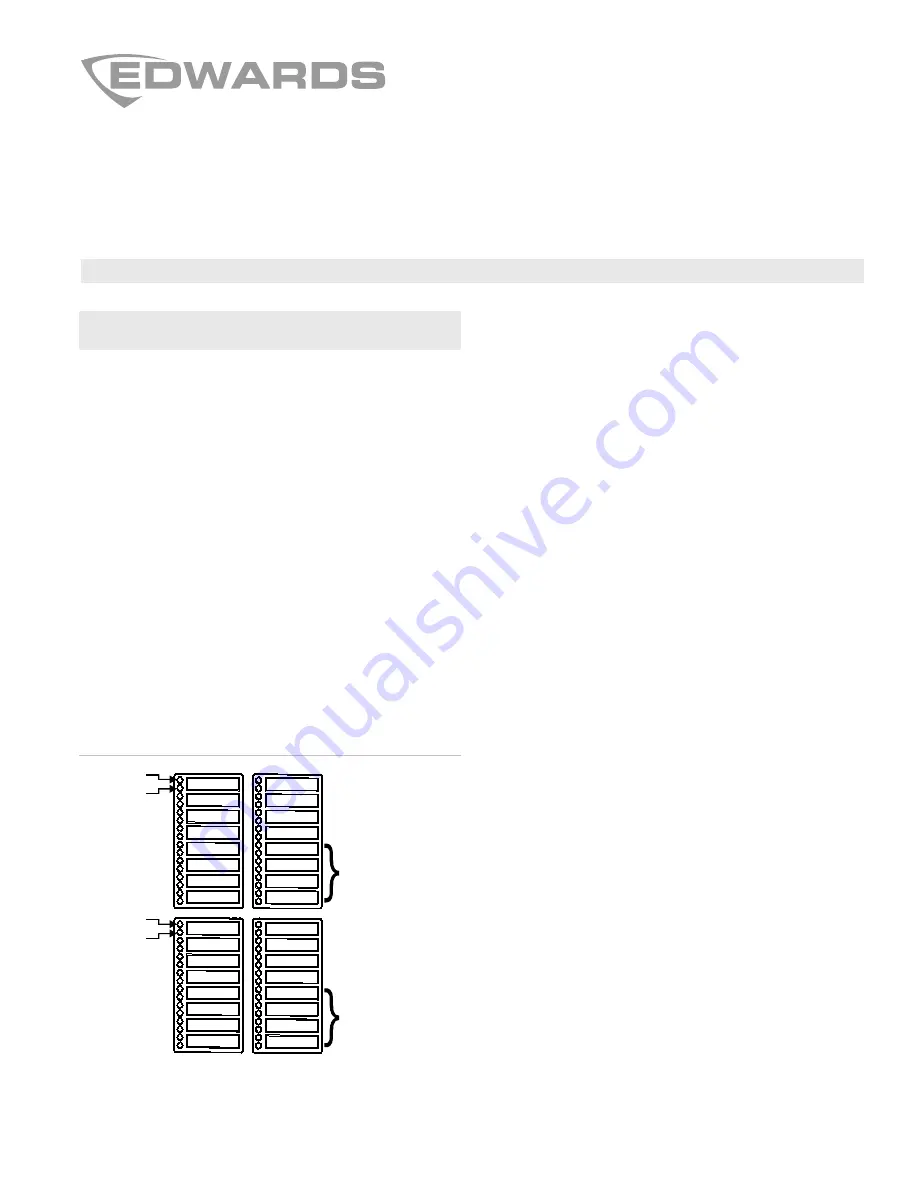
Figure 1: LED zone designations
Zone 16
Zone 13
Zone 32
Zone 29
Zone 1
Zone 17
LED 1
LED 2
LED 1
LED 2
Alarm/Non-alarm
and trouble
zone LEDs
Alarm/Non-alarm
and trouble
zone LEDs
LED
expander 1
LED
expander 2
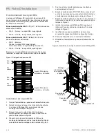
LED installation
1. Power down the panel and disconnect the batteries.
2. Remove the screws securing the right and left side LED
display expander assemblies, and then remove each
expander assembly as shown in Figure 2.
3. Remove the blank overlay from the front of the LED
display expander, and then install the new annunciator
overlay in its place as shown in Figure 2.
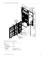
4. Position the LED PCB on the expander assembly with the
holes in the PCB aligned to the pins in the expander
assembly as shown in Figure 3.
5. Secure the PCB under the clips as shown in Figure 3.
6. Connect the ribbon cable (P/N 7140196) from connector
J1 on the top expander to connector J6 on the main circuit
board as shown in Figure 3.
7. Connect the ribbon cable from connector J1 on the bottom
expander to connector J2 on the left expander as shown in
Figure 3.
8. Install the top and bottom LED display expanders and
secure using #6 plastite screws as shown in Figure 2.
9. Identify each LED according to its programmed zone using
the labels provided.
10. Install the labels in the annunciator overlay.
11. Power up the panel and connect the batteries.