background image


LPC P-cap Series User Manual 

Panel PC, Intel® Braswell Celeron®3160, IP65 Compliant 

Bezel & Wide Range Power Input


Published in Taiwan 

Release Date : Oct 2017 

Revision : V1.0 


Warning! 

This equipment generates, uses and can radiate radio frequency energy and if not installed and used in 

accordance  with  the  instructions  manual,  it  may  cause  interference  to  radio  communications.  It  has 

been tested and found to comply with the limits for a Class A computing device pursuant to FCC Rules, 

which  are  designed  to  provide  reasonable  protection  against  such  interference  when  operated  in  a 

commercial  environment.  Operation  of  this  equipment  in  a  residential  area  is  likely  to  cause 

interference in which case the user at his own expense will be required to take whatever measures may 

be required to correct the interference. 


Electric Shock Hazard 

 Do not operate the machine with its back cover removed. There are dangerous 

high voltages inside. 

Summary of Contents for LPC P-cap Series

Page 1: ...ions It has been tested and found to comply with the limits for a Class A computing device pursuant to FCC Rules which are designed to provide reasonable protection against such interference when oper...

Page 2: ...kage are Panel Mounting Kits 3 Pin Male Terminal Block Optional Adapter Other ___________________ please specify Safety Precautions Follow the messages below to avoid your systems from damage Avoid yo...

Page 3: ...cations 5 1 3 Dimension 7 1 4 General Rear IO Replacement 16 1 5 Front View 17 1 6 Rear View 18 1 7 Installation of HDD 19 Chapter 2 Main Board Introduction 2 1 Mainboard Specification 21 2 2 Jumpers...

Page 4: ...llation of Drivers 5 1 Windows 7 Patch Setup 58 5 2 Chipset Driver Setup 61 5 3 Audio Driver Setup 63 5 4 Graphics Driver Setup 65 5 5 LAN Driver Setup 67 5 6 SIO Driver Setup 69 5 7 TXE Driver Setup...

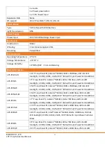
Page 5: ...56W LPC P156W 01 Max Resolution 1024 768 1024 768 1366 768 1920 1080 Color 16 7M 16 2M 16 7M 16 2M Luminance 350 nits 420 nits 300 nits 400 nits View Angle 160 160 160 160 160 170 140 120 Contrast Rat...

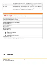
Page 6: ...h 3 pin Power Terminal Block LPC P156W 15 6 P cap Panel PC Celeron N3160 1366 x 768 Reso 300 nits LED backlight 4 COM 4 USB 2 LAN DC 9 36V with 3 pin Power Terminal Block LPC P156W 01 15 6 P cap Panel...

Page 7: ...r current protection Output short circuit protection Order Information LPC PxxxS W H OB G AG AR B V T xxx size For example 10 1 101 S Dimension Ratio Square 4 3 or 5 4 W Dimension Ration Wide 16 9 or...

Page 8: ...ELGENS CO LTD LPC P cap Series User Manual 8 LPC P121S 01 Drawing...

Page 9: ...ELGENS CO LTD LPC P cap Series User Manual 9 LPC P150S Drawing...

Page 10: ...ELGENS CO LTD LPC P cap Series User Manual 10 LPC P156W 156W 01 Drawing...

Page 11: ...ELGENS CO LTD LPC P cap Series User Manual 11 LPC P170S Drawing...

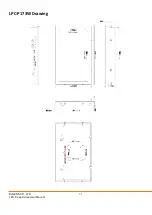
Page 12: ...ELGENS CO LTD LPC P cap Series User Manual 12 LPC P173W Drawing...

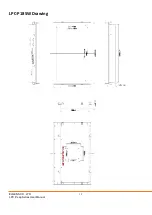
Page 13: ...ELGENS CO LTD LPC P cap Series User Manual 13 LPC P185W Drawing...

Page 14: ...ELGENS CO LTD LPC P cap Series User Manual 14 LPC P190S Drawing...

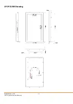
Page 15: ...ELGENS CO LTD LPC P cap Series User Manual 15 LPC P215W Drawing...

Page 16: ...ELGENS CO LTD LPC P cap Series User Manual 16 1 4 General Rear IO Placement COM 1 is RS 485 as below pin definition adjustable to RS 422 by BIOS Power input terminal block pin definition is as below...

Page 17: ...ELGENS CO LTD LPC P cap Series User Manual 17 1 5 Front View of LPC Pcap Series...

Page 18: ...ELGENS CO LTD LPC P cap Series User Manual 18 1 6 Rear View of LPC Pcap Series...

Page 19: ...O LTD LPC P cap Series User Manual 19 1 7 Installation of HDD Below example is LPC P185W 1 7 1 Remove screws from below red circles Notice below screws located in right and left side should be removed...

Page 20: ...ve the casing we will see as below HDD is designed to fix with mounting bracket DRAM is located the bottom side of main board as a result we strongly suggest our client to purchasing DRAM from ELGENS...

Page 21: ...ELGENS CO LTD LPC P cap Series User Manual 21 Chapter 2 Main Board Introduction 2 1 Mainboard Specification 2 1 1 Mainboard Overview...

Page 22: ...Side 2 1 3 Mainboard Dimensions IO side 2 1 4 Mainboard Specifications Mainboard Specifications Board Size 146 mm x 102 mm 3 5 inch size Processor Intel Celeron N3160 Processor Chipset Integrated in...

Page 23: ...to 2560 x 1600 60 Hz 3840 x 2160 30 Hz Supports three independent displays LVDS HDMI Display Port Battery Support CR2477 Li battery by 2 pin header Audio Realtek ALC887 VD2 CG HD Audio Codec 1 x Front...

Page 24: ...User Manual 24 2 2 Jumpers Setting and Connectors Power Supply DC In Power Connector JPWR1 This connector is used to provide power to the motherboard SATA Power Connector JPW1 This connector is used t...

Page 25: ...he black wire is Ground and should be connected to GND If the motherboard has a System Hardware Monitor chipset onboard you must use a specially designed fan with speed sensor to take advantage of the...

Page 26: ...el switches LEDs and is compliant with Intel Front Panel I O Connectivity Design Guide Front Audio Connector JAUD1 This connector allows you to connect the front panel audio and is compliant with Inte...

Page 27: ...provided for the General Purpose Input Output GPIO peripheral module RS232 Serial Port Connector JCOM2 JCOM3 JCOM4 This connector is a 16550A high speed communications port that sends receives 16 byt...

Page 28: ...s User Manual 28 RS232 422 485 Serial Port Connector JCOM1 This connector is a 16550A high speed communications port that sends receives 16 bytes FIFOs You can attach a serial device to it through an...

Page 29: ...tial Signal connector provides a digital interface typically used with flat panels After connecting an LVDS interface flat panel to the JLVDS1 be sure to check the panel datasheet and set the LVDS jum...

Page 30: ...l I O Connectivity Design Guide is ideal for connecting high speed USB interface peripherals such as USB HDD digital cameras MP3 players printers modems and the like Important Note that the pins of VC...

Page 31: ...data of system configuration With the CMOS RAM the system can automatically boot OS every time it is turned on If you want to clear the system configuration set the jumper to clear data Important You...

Page 32: ...OMP1 The jumper specifies the operation voltage of the specified serial port LVDS Power Jumper JVDD1 Use this jumper to specify the operation voltage of the LVDS display LVDS Inverter Power Jumper JIN...

Page 33: ...other Mini PCIe cards MINI_PCIE1 supports Mini PCIe and mSATA cards MINI_PCIE2 only supports Mini PCIe cards Important When adding or removing expansion cards make sure that you unplug the power supp...

Page 34: ...the illustrations in this chapter should be held for reference only Entering Setup Power on the computer and the system will start POST Power On Self Test process When the message below appears on the...

Page 35: ...sub menu contains additional options for a field parameter You can use arrow keys to highlight the field and press Enter to call up the sub menu Then you can use the control keys to enter values and m...

Page 36: ...e this menu to specify the priority of boot devices Security Use this menu to set supervisor and user passwords Chipset This menu controls the advanced features of the onboard chipsets Power Use this...

Page 37: ...Date This setting allows you to set the system date The date format is Day Month Date Year System Time This setting allows you to set the system time The time format is Hour Minute Second SATA Mode S...

Page 38: ...nds of delay to the booting sequence This delay ensures that the logo is displayed for a sufficient amount of time Therefore it is recommended that you disable this BIOS feature for a faster boot up t...

Page 39: ...al port Mode Select Select an operation mode for the specified serial port FIFO Mode This setting controls the FIFO data transfer mode Shared IRQ Mode This setting provides the system with the ability...

Page 40: ...O LTD LPC P cap Series User Manual 40 H W Monitor These items display the current status of all monitored hardware devices components such as voltages temperatures and all fans speeds Smart Fan Config...

Page 41: ...SYSFAN Target This setting enables disables the Smart Fan function Smart Fan is an excellent feature which will adjust the CPU system fan speed automatically depending on the current CPU system temper...

Page 42: ...n independent partitions With virtualization one computer system can function as multiple Virtual systems EIST EIST Enhanced Intel SpeedStep Technology allows the system to dynamically adjust processo...

Page 43: ...he operating system that does not support or have any USB 1 1 2 0 driver installed such as DOS and SCO Unix Audio Controller This setting enables disables the onboard audio controller Launch OnBoard L...

Page 44: ...ELGENS CO LTD LPC P cap Series User Manual 44 GPIO Group Configuration GPO0 GPO3 These settings control the operation mode of the specified GPIO...

Page 45: ...eo mode OS Selection This setting allows users to select the Operating System Boot Option Priorities This setting allows users to set the sequence of boot devices where BIOS attempts to load the disk...

Page 46: ...cap Series User Manual 46 Security Administrator Password Administrator Password controls access to the BIOS Setup utility User Password User Password controls access to the system at boot and to the...

Page 47: ...er Manual 47 Trusted Computing Security Device Support This setting enables disables BIOS support for security device When set to Disable the OS will not show security device TCG EFI protocol and INT1...

Page 48: ...ave a monitor and keyboard attached This setting enables disables the operation of console redirection When set to Enabled BIOS redirects and sends all contents that should be displayed on the screen...

Page 49: ...e flow of data from one device to another to ensure that the receiving device can handle all of the incoming data This is particularly important where the sending device is capable of sending data muc...

Page 50: ...ion of the Intel Trusted Execution Engine TXE TXE HMRFPO The setting enables disables TXE HMRFPO Host ME Region Flash Protection Override TXE Firmware Update This setting enables disables TXE FW updat...

Page 51: ...system DVMT Total Gfx Mem This setting specifies the memory size for DVMT LCD Panel Type This setting specifies the LCD panel type LVDS Backlight Control This setting controls the intensity of the LVD...

Page 52: ...whether your system will reboot after a power failure or interrupt occurs Available settings are Power Off Leaves the computer in the power off state Power On Leaves the computer in the power on state...

Page 53: ...omponents may remain powered so the computer can wake on input from the keyboard clock modem LAN or USB device Advanced Resume Events Control PCIE PME This field specifies whether the system will be a...

Page 54: ...nges Load Optimized Defaults Use this menu to load the default values set by the motherboard manufacturer specifically for optimal performance of the motherboard Save as User Defaults Save changes as...

Page 55: ...re when you install OS This tool can make your own bootable Windows 7 USB from your original Windows 7 disk Things need to prepare Prepare your Windows 7 DVD and an USB disk at least 8Gb Put the DVD i...

Page 56: ...status bar reach to 100 withdraw the USB device and done Step A A 1 Plug your modified USB to USB 3 0 port and keyboard A 2 Then turn on the LPC series press Delete to enter BIOS mode A 3 In BIOS mod...

Page 57: ...57 A 4 Select your Modified USB disk as Boot Option 1 A 5 Then go to Save Exit page choose Save Changes and Reset A 6 Then the Win 7 installation will appear on the screen Now you can install Windows...

Page 58: ...ies User Manual 58 Chapter 5 Installation Drivers 1 Windows 7 Patch Setup 1 1 Go to X Win_patch Choose NDP451 KB2858728 x86 x64 AllOS ENU exe 1 2 Choose Yes 1 3 Choose I have read and accept the licen...

Page 59: ...ELGENS CO LTD LPC P cap Series User Manual 59 1 4 Then press Finish 1 5 Choose 32 or 64 Bit installation file...

Page 60: ...ELGENS CO LTD LPC P cap Series User Manual 60 1 6 Choose Yes 1 7 After installation choose Restart Now...

Page 61: ...ELGENS CO LTD LPC P cap Series User Manual 61 2 Chipset Driver Setup 2 1 Go to X Chipset and choose SetupChipset exe 2 2 Choose Next 2 3 Choose Accept...

Page 62: ...ELGENS CO LTD LPC P cap Series User Manual 62 2 4 Choose Install 2 5 Choose Yes and wait to complete the installation...

Page 63: ...ELGENS CO LTD LPC P cap Series User Manual 63 3 Audio Driver Setup 3 1 Go to X Audio and choose Setup exe 3 2 Choose Yes and wait until the installation is completed...

Page 64: ...ELGENS CO LTD LPC P cap Series User Manual 64 3 3 Choose Yes I Want to restart my computer now and press OK to restart...

Page 65: ...aphics Driver Setup 4 1 Go to X Graphics 4277 Win7 8 1 64bit win64 and choose Setup exe according to your OS 32 bits or 64 bits This SOP is based on Win 7 64 Bit 4 2 Choose Yes 4 3 Choose Next and the...

Page 66: ...ELGENS CO LTD LPC P cap Series User Manual 66 4 4 Yes I Want to restart my computer now Finish...

Page 67: ...ELGENS CO LTD LPC P cap Series User Manual 67 5 LAN Driver Setup 5 1 Go to X LAN Install_Win7_7097_11232015 and choose Setup exe 5 2 Choose Yes 5 3 Choose Next...

Page 68: ...ELGENS CO LTD LPC P cap Series User Manual 68 5 4 Choose Install 5 5 Choose Finish to complete the installation...

Page 69: ...LTD LPC P cap Series User Manual 69 6 SIO Driver Setup 6 1 Go to X SIO 1 2 3 0616 Win7 and choose Intel Processor Win7 IO Drivers 64Bit msi according your OS by 32 or 64 Bits This SOP is based on Win...

Page 70: ...D LPC P cap Series User Manual 70 6 2 Choose Next 6 3 Choose I accept the terms in the license agreement and Next Install Yes OK until the installation is completed 6 4 Choose Finish to complete the i...

Page 71: ...ELGENS CO LTD LPC P cap Series User Manual 71 7 TXE Driver Setup 7 1 Go to X TXE and choose SetupTXE exe...

Page 72: ...S CO LTD LPC P cap Series User Manual 72 7 2 Choose Yes and Next 7 3 Choose I accept the terms in the license agreement and Next until the installation is completed 7 4 Choose Finish after the install...

Page 73: ...ELGENS CO LTD LPC P cap Series User Manual 73 8 USB3 0 Driver Setup 8 1 Go to X USB3 0 4 0 3 49 and choose Setup exe 8 2 Choose Yes Next and Yes until the installation is completed...

Page 74: ...ELGENS CO LTD LPC P cap Series User Manual 74 8 3 Choose Finish until the installation is completed...

Page 75: ...User Manual 75 Chapter 6 Touch Screen Driver Installation Touch Driver installation for Windows 7 1 Install Touch Driver in DVD ROM 2 Go to file of X EETI Touch Driver eGalaxTouch_5 11 0 9126 then cho...

Page 76: ...ELGENS CO LTD LPC P cap Series User Manual 76 3 Choose Yes to start installation 4 Choose Next...

Page 77: ...ELGENS CO LTD LPC P cap Series User Manual 77 5 Choose Next 6 Choose Next...

Page 78: ...ELGENS CO LTD LPC P cap Series User Manual 78 7 Choose Next 8 Choose OK...

Page 79: ...ELGENS CO LTD LPC P cap Series User Manual 79 9 Choose Next 10 Choose Next...

Page 80: ...ELGENS CO LTD LPC P cap Series User Manual 80 11 Choose Next 12 Choose Next...

Page 81: ...ELGENS CO LTD LPC P cap Series User Manual 81 13 Waif for installation to complete 14 Choose Yes for 4 points calibration...

Page 82: ...libration point When it shows OK please remove your finger from the touch screen Please repeat it for next 3 calibration points It requires totally 4 calibration points for complete touch screen insta...

Page 83: ...nge to WDT mov dx SIO_INDEX_Port mov al 07h out dx al mov dx SIO_DATA_Port mov al WatchDog_LDN out dx al Acive WDT mov dx SIO_INDEX_Port mov al 30h out dx al mov dx SIO_DATA_Port in al dx or al 01h ou...

Reviews: