

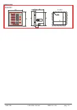
ELM-961
instruction manual
IM441-U v0.6
pag. 1
INSTRUCTION MANUAL
IM441-U v0.6
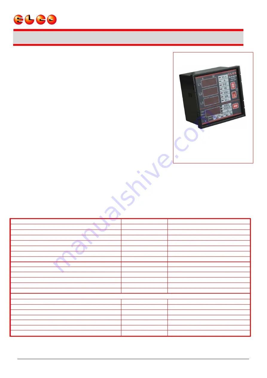
ELM-961
ELECTRICAL MULTIFUNCTION METER
GENERALITY
These digital multimeters series allow to monitor all the electrical parameters
present on a distribution line. The local display of 30 electrical parameters is
carried out by 4 display with red LED guaranteeing a good and contemporary
reading of more measures. A simple front panel completes the intuitive
selection of several electrical parameters, with a great quantity of information.
These instruments, over of the instantaneous measures, display the
maximum peak of the main parameters (maximum peak and maximum
demand).
The presence of the serial port communication EIA485 (option) allows the
connection in network of more instruments to realize centralized measure
networks.
These multimeters replace in a unique device, all the functions of voltmeters,
ammeters, energy meters, cosphimeters, wattmeters, varmeters, frequency
meters permitting a great economic saving, a reduction of dimension and the
wiring energy and a simplification in the purchase and management of the
instruments because this is a model usable at all of need of local measure in
the electrical panel, machine, etc.
OPTIONS
- internal CT
- digital output (in alternative to the serial port)
- serial port (in alternative to the digital output)
- power supply different from standard version
- current input 1A
MEASURED PARAMETERS
parameters
unit of measurement
initial identification
phase and three phase voltages
[V-kV]
V
L1-N
V
L2-N
V
L3-N
Σ
V
L-N
phase to phase and three phase system voltages
[V-kV]
V
L1-L2
V
L2-L3
V
L3-L1
Σ
V
L-L
phase and three phase currents
[A-kA]
A
L1
A
L2
A
L3
Σ
A
phase and three phase power factors
PF
L1
PF
L2
PF
L3
Σ
PF
phase and three phase active powers
[W-kW-MW]
W
L1
W
L2
W
L3
Σ
W
phase and three phase system reactive powers
[VAr-kVAr-MVAr]
VAr
L1
VAr
L2
VAr
L3
Σ
VAr
phase and three-phase system apparent powers
[VA-kVA-MVA]
VA
L1
VA
L2
VA
L3
Σ
VA
frequency
[Hz]
Hz
L3
temperature
[°C]
T
three phase system active energy
[kWh]
Σ
kWh
three phase system reactive energy
[kVArh]
Σ
kVArh
three phase system apparent energy
[kVAh]
Σ
kVAh
hours counter
[hr]
h
peak value (maximums):
maximum phase voltages
[V-kV]
V
L1-N max
V
L2-N max
V
L3-N max
maximum phase currents
[A-kA]
A
L1 max
A
L2 max
A
L3 max
maximum three-phase powers
[W-VAr-VA (k-M)]
Σ
W
max
Σ
VAr
max
Σ
VA
max
maximum average phase currents (maximum demand)
[A-kA]
I
L1 max (avg)
I
L2 max (avg)
I
L3 max (avg)
maximum average three-phase powers (maximum demand) [W-VAr-VA (k-M)]
Σ
W
max (avg)
Σ
VAr
max (avg)
Σ
VA
m x (avg)
a
average phase currents
[A-kA]
A
L1 avg
A
L2 avg
A
L3 avg
average three-phase powers
[W-VAr-VA (k-M)]
Σ
W
avg
Σ
VAr
avg
Σ
VA
avg


