background image

Super Clock

Super Clock

Super Clock

Super Clock

Super Clock

SC-5

SC-5

SC-5

SC-5

SC-5

Operating Instructions

Operating Instructions

Operating Instructions

Operating Instructions

Operating Instructions

OI 0313961

Electronics International Inc. 

Electronics International Inc. 

Electronics International Inc. 

Electronics International Inc. 

Electronics International Inc. 

®

®

®

®

®

3/13/96

Rev C: 11/22/22

63296 Powell Butte Hwy  •  Bend, OR 97701  •   (541) 318-6060  • iFlyEi.com 

63296 Powell Butte Hwy  •  Bend, OR 97701  •   (541) 318-6060  • iFlyEi.com 

63296 Powell Butte Hwy  •  Bend, OR 97701  •   (541) 318-6060  • iFlyEi.com 

63296 Powell Butte Hwy  •  Bend, OR 97701  •   (541) 318-6060  • iFlyEi.com 

63296 Powell Butte Hwy  •  Bend, OR 97701  •   (541) 318-6060  • iFlyEi.com 

You must read this manual before installing or operating the instrument.  This

manual contains warranty and other information that may affect your decision

to install this product and/or the safety of your aircraft.

D-Sub

Summary of Contents for Super Clock SC-5

Page 1: ...nal Inc 3 13 96 Rev C 11 22 22 63296 Powell Butte Hwy Bend OR 97701 541 318 6060 iFlyEi com 63296 Powell Butte Hwy Bend OR 97701 541 318 6060 iFlyEi com 63296 Powell Butte Hwy Bend OR 97701 541 318 6060 iFlyEi com 63296 Powell Butte Hwy Bend OR 97701 541 318 6060 iFlyEi com 63296 Powell Butte Hwy Bend OR 97701 541 318 6060 iFlyEi com You must read this manual before installing or operating the ins...

Page 2: ...2 Blank Page ...

Page 3: ...und Contact Electronics International Inc for details It is possible for any instrument to fail thereby displaying inaccurate high low or jumpy readings Therefore you must be able to recognize an instrument failure and you must be proficient in operating your aircraft safely in spite of an instrument failure If you do not have this knowledge contact the FAA or a local flight instructor for trainin...

Page 4: ...4 Blank Page ...

Page 5: ...LED Display Mode Indicators 8 2 UP Timer Warning LED 8 3 DN Timer Warning LED 8 4 Power Up 8 5 LOCAL Clock Display Mode 8 6 ZULU Clock Display Mode 9 7 UP Clock Display Mode 9 8 DN Clock Display Mode 10 9 ENGINE TIME Clock Display Mode 11 Power upProgramming 12 Specifications and Operating Features 14 FAALetter 15 5 ...

Page 6: ... installer due to factory updates modifications improvements upgrades changes or any other alterations to the prod uct that may affect the form fit function or operation of the product 5 Personal injury or property damage do to misinterpretation or lack of understanding this product is solely the pilots responsibility The pilot must understand the operation of this product before flying the aircra...

Page 7: ...et an alarm at 30 minutes 60 minutes 90 minutes etc This alarm can be used to remind you to check your fuel level course position or instruments at set time intervals The yellow Warning LED marked UP over the digital display will blink when the programmed time interval is reached The START STOP and RESET buttons control this Timer 4 DN Timer In this mode the SC 5 will display the DN Timer This Tim...

Page 8: ...on or switch to stop the blinking and tum off the UP Timer Warning LED The UP Timer Display Mode section of this manual explains more about the operation of this alarm 3 DN Timer Warning LED The DN Timer Warning LED located over the digital display will blink when the DN Timer reaches 0 00 Push any button or switch to stop the blinking and turn off the DN Timer Warning LED The DN Timer Display Mod...

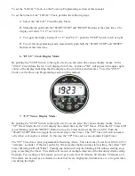
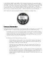
Page 9: ...y pushing the STEP Switch to the right or left you can select the various display modes In the UP Timer Mode the SC 5 will display the current time on the UP Timer When the UP Timer LED is not blinking push the RESET Button to stop the Timer and reset the time to 0 00 Push the START STOP Button to toggle the start and stop of this Timer The UP Time will start automati cally when your engine is sta...

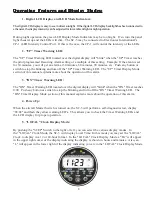
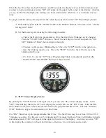
Page 10: ... Digit Move the STEP Switch to the right to in crease the blinking digit by one Move the STEP Switch to the left to decrease the blinking digit by one c To Exit To exit the UP Timer Programming Mode momentarily push bot hthe START STOP and RESET Buttons at the same time 8 DN Timer Display Mode By pushing the STEP Switch to the right or left you can select the various display modes In the DN Timer ...

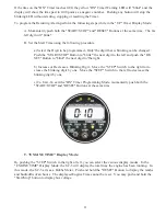
Page 11: ...xt digit to the left and push the RE SET Button to blink the next digit to the right b Increase or Decrease a Blinking Digit Move the STEP Switch to the right to in crease the blinking digit by one Move the STEP Switch to the left to decrease the blinking digit by one c To Exit To exit the DN Timer Programming Mode momentarily push both the START STOP and RESET Buttons at the same time 9 ENGINE TI...

Page 12: ...perform the following steps A With the aircraft power off push and hold both the START STOP and RESET Buttons and turn the aircraft power on The far left hours digits will be blinking An L will be showing in the lower right corner of the display indicating you are setting the Local Clock The Local and Zulu Clocks are always set in a 24 hour format B Set the Local Clock using the following procedur...

Page 13: ...t only in one hour time zones set the display to Loc In this configuration when the Local Clock is set to a standard the Zulu Clock minutes will automatically be set to the correct time If you operate your aircraft in half hour time zones set the display to ULoc In this configura tion the Local and Zulu Clock work independently of each other To go back to programming the Zulu Clock or Local Clock ...

Page 14: ...ledge the alarm and turn off the UP Timer Warning LED Yellow DN Timer Warning LED The DN Timer Warning LED located over the digital display will blink when the DN Timer reaches 0 00 Push any button or switch to stop the blinking and turn off the DN Timer Warning LED Digital Display LCD viewable in direct sunlight with 12 and 24 volt backlight control wires for night operation Displays 88 88 on pow...

Page 15: ...15 ...

Page 16: ...16 ...

Reviews: