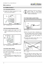
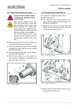
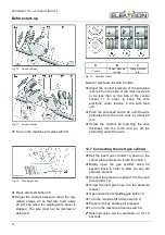
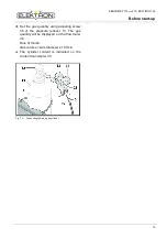
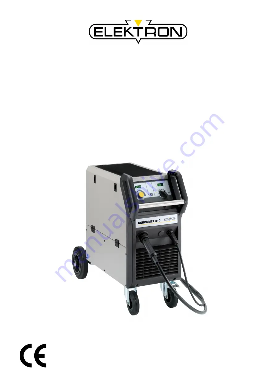
background image


Made in Germa n y 

Operation Manual 

KERCOMET 170 

and

 210 

MULTIMIG 150 

MIG / MAG - Welding machine 


Item-No: 

327 972 

Revision: 

1.0 - Original 

Version: 

31.01.2013 

Be sure you have read and understood this operating 
manual before you carry out any works on and/or with this 
equipment!


Summary of Contents for KERCOMET 170

Page 1: ...KERCOMET 170 and 210 MULTIMIG 150 MIG MAG Welding machine Item No 327 972 Revision 1 0 Original Version 31 01 2013 Be sure you have read and understood this operating manual before you carry out any works on and or with this equipment ...

Page 2: ...mbH Branch Bremen Hinterm Sielhof 22 D 28277 Bremen Germany Phone 49 0 421 54 90 6 906 Fax 49 0 421 54 90 6 19 E Mail vertrieb elektron bremen de Internet www elektron bremen de Release BlitzRotary GmbH Branch Bremen ...

Page 3: ... 10 12 4 Fastening the ground clamp 10 12 5 Insert the welding wire spool 11 12 6 Thread the wire electrode in 11 12 7 Connecting the inert gas cylinder 12 12 8 Changing the wire electrode 14 13 Start up 16 13 1 Control console KERCOMET 170 and MULTIMIG 150 16 13 2 Control console KERCOMET 210 18 13 3 Current voltage display 19 13 4 Characteristic connection 20 13 5 Main parameters 21 13 6 Seconda...

Page 4: ...in for gas 2 Hoisting points 3 Mains cable 4 Mains voltage changeover switch on switch able units only 5 Gas hose 6 Tray area 7 Handle 8 Control panel 9 Main switch 10 Socket for ground cable 11 Central socket Some depicted or described acces sories are not included in the scope of delivery Subject to change ...

Page 5: ...etely and strictly ob serve them Please obtain practical training be fore using the machine for the first time Follow the accident preven tion regulations UVV 1 Before starting any welding work clear away any solvents degreasing agents and other flammable materials from the working area Cover flammable materials which can not be moved Only weld if the ambient air contains no high concentrations of...

Page 6: ...ur wire system with grounded neutral conductor or single phase three wire system with grounded neutral conductor socket and extension cable must have a functional protective conductor Wear correct protective clothing leather gloves and leather apron Protect the welding area with curtains or mobile screens Do not use this machine to thaw frozen water pipes or cables In closed containers under cramp...

Page 7: ...m 9 Electromagnetic compatibility EMC This product is manufactured in conformance with the current EMC standard Please note the following The machine is intended for welding in both commercial and industrial applications CISPR 11 class A Use in other surroundings for example in residential areas may disturb other electronic devices Electromagnetic problems during start up can arise in Mains cables...

Page 8: ...ng point must be loaded separately Do NOT for example put one load strap through both handles as this could lead them to be pulled together and cause breakage Do not use a fork lift truck or similar device to lift the machine by its housing Remove the gas cylinder from the welding machine before transpor tation The machine must be transported or set up only on firm level sur faces The maximum admi...

Page 9: ... piece Insert wire feed rollers 25 into wire feed unit in accordance with the type of welding wire selected set contact pressure to 2 Connect the torch to central connector 11 and insert the relevant contact tip to se lected welding wire Insert welding wire Keep torch switch pressed and set main switch 9 ON Magnetic valve will be ac tivated Adjust gas quantity at pressure reducer Rule wire diamete...

Page 10: ...For 230 V operation the adapter CEE 16 on shock proof plug incl in delivery may be used Performance values are limited in 230 V mode i e max welding power is limited to 2 3 of the values stated in technical data 12 4 Fastening the ground clamp Fig 5 Correct Attach the ground clamp immediately be side the welding point so that the welding current will not try to find its own return path through mac...

Page 11: ...he wire spool holder 22 Place the welding wire reel on the decoiler mandrel and ensure that the carrier mandrel 23 locks in position For small welding wire reels use an adaptor order number 420 922 Set the wire brake 21 so that when the torch switch is released the welding wire spool just does not run on Fig 7 Decoiler mandrel 12 6 Thread the wire electrode in Unscrew the contact tip of the torch ...

Page 12: ...tral socket 11 in order to keep the wire electrode under tension in the wire feed unit Push the wire feed button 29 until the wire protrudes from the torch neck by about 20 mm Screw the contact tip matching the wire thickness into the torch and cut off the protruding end of the wire 12 7 Connecting the inert gas cylinder Set the insert gas cylinder 14 down on the carrier plate and secure it with t...

Page 13: ...uantity using adjusting screw 35 of the pressure reducer 13 The gas quantity will be displayed on the flow meter 34 Rule of thumb Gas volume wire diameter x 10 l min The cylinder content is indicated on the content manometer 33 Fig 14 Connecting the inert gas cylinder ...

Page 14: ...fer to the operating manual for the torch Insert the guide tube 85 into the central connection Plastic core for aluminium stainless steel or CuSi wire Remove the existing wire feed spiral or plastic core and insert the new plastic core Refer to the operating manual for the torch Remove the guide tube 85 from the central connection Shorten the protruding plastic core so that it is tight up against ...

Page 15: ...ntral connection torch 25 Wire feed roller 38 Retaining nipple clamp of the plastic liner for 4 0 mm and 4 7 mm outside diameter 39 O ring 40 Union nut 41 Plastic liner 42 Support tube for plastic cores with 4 mm OD Support tube not required with OD of 4 7 mm 43 Guide tube 44 Wire feed spiral ...

Page 16: ...KERCOMET 170 and 210 MULTIMIG 150 Start up 16 13 Start up 13 1 Control console KERCOMET 170 and MULTIMIG 150 Fig 17 Control console KERCOMET 170 and MULTIMIG 150 ...

Page 17: ...l material thickness lights up if the 7 segment display 47 displays the material thickness in mm 56 Main switch for turning the welding machine ON and OFF 57 Step switch material thickness welding step by setting the step switch for approx 2 seconds the material thickness alt welding step will be displayed in the 7 segment display 47 58 Symbol 230 V lights up if 230 V is selected applicable for un...

Page 18: ...KERCOMET 170 and 210 MULTIMIG 150 Start up 18 13 2 Control console KERCOMET 210 Fig 19 Control console KERCOMET 210 ...

Page 19: ...e see chapter characteristic setting or mode either the material thickness welding voltage or secondary parameter codes will be displayed 56 Main switch for switching the welding unit ON and OFF 57 Step switch material thickness welding voltage for adjusting the material thickness alt the welding voltage values will be displayed in the 7 segment display 55 58 Symbol 230 V lights up if 230 V weldin...

Page 20: ...cteristic table Read the corresponding characteristic number off from the right hand column Set the corresponding number from the table using selection knob 65 Below the characteristic number 0 manual mode Is the material wire gas combination nullified Wire feed and welding voltage can be set manually The welding step Basic Plus instead of material thickness will be displayed The must value for we...

Page 21: ...e al ternately KERCOMET 170 MULTIMIG 150 The 7 segment display 47 displays the sec ondary parameter value the 7 segment display 55 displays the secondary param eter code KERCOMET 210 Press the mode key 60 until the required secondary parameter code is displayed Set the required secondary parameter value using turning knob 61 Exit the secondary parameter by pressing the mode key 60 for at least 2 s...

Page 22: ...ey can interrupt the gas test Fan test Turn the unit ON using main switch 9 The fan will start for function purposes Operation panel test Press the mode key 60 for at least 5 sec onds All operation displays will flash for approx 20 seconds 13 8 Reset setting Master reset Attention All personal settings will be lost All welding and secondary param eters are reset to their factory set tings Turn the...

Page 23: ...he work piece cable and ground clip check for short circuits between welding wire and housing Check emergency stop chain E04 2 Emergency STOP periphery fault optional Gas pressure switch input activated Check inert gas E06 Over voltage Output voltage too high Inform Service E07 EEProm checksum error Setting data faulty or missing Switch the equipment off and on again E08 Wire feed Too high power i...

Page 24: ... missing or dirty Insert the guide tube or clean it Welding wire reel badly wound Check and replace if necessary Surface rust on wire electrode Check and replace if necessary Torch internal coil clogged with abrasion dust Unscrew the torch from the equipment remove contact tip from torch and blow out the coil with compressed air Torch internal coil flexed Check and replace if necessary Wire brake ...

Page 25: ... pressure reducing nozzle Torch or gas hose blocked or leaking Check and replace if necessary Inert gas blown away by draughts Eliminate the draughts Welding power is reduced Phase missing Check the equipment using a different power socket check the supply cable and the mains fuses Insufficient ground contact at work piece Create a good clear ground connection Ground cable not correctly inserted a...

Page 26: ...ew both side panels of the unit Blow out the welding machine with dry low pressure compressed air Avoid blowing directly on the electronic components from a short distance to prevent damage Screw the two side panels onto the machine back again Never make repairs or technical changes yourself In this case the manufacturer s warranty is no longer valid If you experience problems or need repairs cont...

Page 27: ...1 230 3 400 1 230 3 400 3 400 Positive mains voltage tolerance 15 15 15 Negative mains voltage tolerance 25 25 25 Input power S1 100 kVA 2 1 2 3 3 0 Input power S1 60 kVA 2 8 2 9 3 6 Input power S1 max Current kVA 6 7 9 0 4 5 Current input I1 100 A 5 3 5 7 4 3 Current input I1 60 A 6 9 7 3 5 2 Current input I1 max Strom A 16 8 22 5 6 5 Maximum effective mains current I1eff A 6 5 8 7 4 3 Power fact...

Page 28: ...waste ma terial In accordance with European Council Directive 2002 96 EC on electrical and electronic equipment waste and its implementation in accordance with national law electric tools that have reached the end of their service life must be collected separately and returned to an environmentally compatible recycling facility 20 Service ELEKTRON Bremen GmbH Hinterm Sielhof 22 D 28277 Bremen Germ...

Page 29: ...KERCOMET 170 and 210 MULTIMIG 150 Schematic 29 21 Schematic KERCOMET 170 ...

Page 30: ...KERCOMET 170 and 210 MULTIMIG 150 Schematic 30 22 Schematic KERCOMET 210 ...

Page 31: ...KERCOMET 170 and 210 MULTIMIG 150 Schematic 31 23 Schematic MULTIMIG 150 ...

Page 32: ...BlitzRotary Gm bH Branch Brem en Hinterm Sielhof 22 D 28277 Brem en Phone 49 0 421 54 90 6 906 Fax 49 0 421 54 90 6 19 vertrieb elektron bremen de www elektron bremen de ...

Reviews: