background image


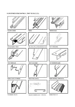
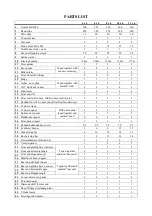
Summary of Contents for 6'3" WIDE THYME

Page 1: ......

Page 2: ......

Page 3: ......

Page 4: ...22 Top door track 1 1 1 1 1 23 Top door panel With name plate taped together and marked door 2 2 2 2 2 24 Bottom door panel 2 2 2 2 2 25 Middle door panel 6 6 6 6 6 26 Door track support 1 1 1 1 1 27 Handed unhanded door posts 2 2 2 2 2 2 2 2 2 2 28 Cantilever bradce 3 6 9 12 15 29 Side glazing bar 6 10 14 18 22 30 Roof glazing bar 5 9 13 16 20 31 Intermediate roof glazing bar 1 1 2 2 2 32 Vent in...

Page 5: ...t play near glass greenhouses REMEMBER glass is fragile handle with care Protective eye glasses should be worn Gloves should be worn If your greenhouse is a painted one there are a few 3mm holes in the end of the bars These are jig holes for painting and have no bearing on construction Key point When powder coated the sub frame assembly packages may slightly differ from the standard alloy finish P...

Page 6: ... draught excluders inc carrier For clear identification of parts and the number required please carefully refer to the earlier pages of component drawings and parts list If your greenhouse is a dwarf wall model the side cills will be the full length of the building up to 20 If your greenhouse is over 12 5 long the longer built in base side walls will be in 2 pieces one of which will be an 8 extens...

Page 7: ...cill to the middle glazing bar by pushing the bolt through the hole in the built in base cill and tightening as before If your greenhouse is over 12 long and built in base model see description and drawing for how to join the 2 base pieces together on previous page Correctly position the built in base cill on the outermost glazing bars by pushing the bolts through the holes in the built in base ci...

Page 8: ...as one per side Side glazing bars 3 if g h is 4 5 long 5 if g h is 6 5 long 7 if g h is 8 5 long 9 if g h is 10 5 long 11 if g h is 12 5 long SIDE FRAME ASSEMBLY For dwarf wall model the built in base in the picture is replaced with the side cill SIDE CILL ...

Page 9: ...ng to the bottom of each roof corner bar and top of each side corner bar do the same with the eaves gusset plate but do not put a nut on the top bolt yet N B if you have a 4 long green house and the roof vent is going to fit to the rear of the greenhouse insert an extra bolt into the roof bar bolt slot If your roof vent is going to fit towards the front of the greenhouse then insert the extra bolt...

Page 10: ...e base legs corner bracket to the end of the base they are 400mm long and have 4 holes at one end bottom and 2 elongated holes at the other end top The elongated hole will line up with the bolt slot of the base and not the corner bar If you are on solid hard standing concrete or patio you will need to cut off the base leg level with the bottom of the base The other side of the angle will later bol...

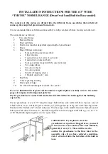
Page 11: ...REAR END ASSEMBLY dotted line indicates corner bracket base leg going into ground ...

Page 12: ...n the bolt channel of the glazing bar as shown in the diagram above Do not attach the other end of the cantilever yet The shelf top section are fitted to the angle supports utilising the bolt channel on the underside of the shelf Insert a bolt into the bolt channel of the shelf Move into position where it will line up with the pre drilled hole in the angle support Put a nut on and tighten The cant...

Page 13: ...bar making it a handed bar The tab is fitted towards the centre of the greenhouse rather than the corner bar Built in base only Now attach the built in base sections cills to the corner bars leaving a space for the door s in between Now engage the door end cill with the 2 built in base cills by pushing the angle of the cill under the locator as shown in the dia gram At this stage the cill will mov...

Page 14: ...g bar and 2 into the bottom of the longer bars Attach 1st and last glazing bar to the hole in the cill using the inserted bolt The higher of the inserted bolts in the longer bars attach to the hole in the tab cill and the lower bolt to the bottom door cill Attach the main door track support shaped like a letter Z to be found with the door panels to the 2 vertical glazing bars ap prox 130mm below t...

Page 15: ...o cut the bracket off level with the bottom of the built in base and slide extra bolts into the bolt channel to be attached to the anchor bracket generally 1 every 2 If you are on soil the bracket will go into the ground at general assembly N B Please note carefully the correct position of the main door support The slotted holes at ei ther end are facing skywards NOT downwards Key point Now insert...

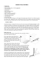
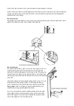
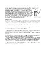
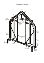
Page 16: ...DOOR END ASSEMBLY ...

Page 17: ...r post on the left handed door post on the right The top of each side post has two screw holes in it the bottom has three Key point Slide the glazing beading into the groove of each bar i e only one length of glazing beading per bar 2 Place the top bottom and 3 infill panels in position as shown by the position of the screw holes in the side pieces and the panels The top panel has the greenhouse n...

Page 18: ...cause it has ball bearings in it The wheel has a collar protruding from the centre this collar goes against the inside face of the top door panel See picture below 8 Slip the nylon door skids on each of the bottom panels This may already have been done prior to delivery 9 Build the right hand door using the remaining handed and unhanded door post Viewed from the outside the handed door post will b...

Page 19: ...DOOR FRAME ASSEMBLY ...

Page 20: ...lide the glazing beading into the slot in the side and top rails and the intermediate glazing bar and trim to suit Insert a bolt into each end of the side rail bolt slots put these bolts through the holes in the top and bottom rails add nuts and lightly tighten Check that all joints are secure and that the vent is square Fit the casement stay using the M4 stainless steel nuts and bolts putting the...

Page 21: ...ROOF VENT ...

Page 22: ...r is outside the end frame and the two flanges that form the angle of the roof and side are inside and tight up against the bolt slots of the roof and side corner bar Key point 3 The extra bolts that were inserted in the bolt slots during the gable end assembly can now be used 4 Line up the elongated holes in the flanges of the eaves with the bolt slots and slide the bolts into them Put a nut on t...

Page 23: ...ition of the roof vent s and insert 1 ad ditional bolt per bar onto which the vent will be fitted This bolt will allow the slam bar fitting In addition your greenhouse comes as standard with cantilever braces on every alternate bar unless you have purchased additional cantilever bars For each cantilever bar you must insert 1 bolt into the bolt channel of each roof bar the cantilever will attach to...

Page 24: ...gs to the base with the end of the brack ets with 4 holes pointing down Mark on the bracket where it is level with the bottom of the built in base Cut off the bracket and discard the end with 4 holes Fix the remaining part of the bracket to the bolt channels of the base in each corner of the greenhouse For fixing on soft standing attach the bracket in the same way as above but do not cut The part ...

Page 25: ...ew groove of the roof corner bar If you are happy that the doors are running smoothly insert a self tapping screw into the smaller hole of the flat bar and in turn into the self tapping groove and tighten Repeat on the other end of the door track This attachment will support the weight of the doors when they are in the open position After fitting the doors you may need to lower the door skid so th...

Page 26: ...through the hole in the panel from the outside Reattach the ring bolt to the barrel on the inside and tighten Now attach the cam lever washer and screw to the door lock from the inside position of the door The lock will turn through 90 degrees both ways so you must ensure the cam when fitted is pointing skywards unlock position and horizontal locked position Now using a cropped head bolt attach th...

Page 27: ...s the door from moving too far along the top door track Repeat at the bottom of the door Repeat for the 2nd door To facilitate smooth running of the door fit 1 flat bar at each end of the top door track The flat bar has 2 holes of different size Loosely fix the larger hole to the bolt channel at the back of the top door track using a short bolt and allow the flat bar to hand vertically down Move t...

Page 28: ...uvre opener consult the fitting instructions inside the automatic louvre box CRESTING AND FINIAL It is easier to fit the cresting s and finials before glazing Place the finial onto the upper flange level with the end of the ridge The slot in the lower part of the finial sits on top of the upper flange Do likewise with the cresting The other end of the ridge has the 2nd finial fitted in a similar m...

Page 29: ... end or rear end of the greenhouse For dwarf wall models the base plan issued by Elite will tell you which way round the doors face This is not interchangeable on dwarf wall models 5 Take the left hand side bar insert 2 bolts into the bolt slot and then offer it up to the eave gutter and cill so that the flange of the cill and the eave are inserted into the saw cuts Key point 6 For built in base m...

Page 30: ...ping part of the cill to facilitate a snug fit 10 Thread the glazing beading into the channels of the glazing bars and trim to suit as previously done 11 You can now attach the vertical glazing bars in the same way as for the door end assembly 12 Now follow the same procedure as earlier for the door end assembly 13 The partition door is slightly lower than the front doors but is built fitted and g...

Page 31: ...the roof of this side but note that you have to use two of the wire clips on the sides of the panes nearest to the roof vent so that the vent will close correctly 6 Repeat on the other side of the house 7 Following this glaze the rear end in a similar fashion When you have 2 pieces of glass butt ing up to each other you butt joint with a PVC muntin The muntins can be found in the small shapes glas...

Page 32: ...6 10 6 4 2 4 12x6 10 2 32 20 10 6 4 2 4 14x6 18 2 36 20 10 6 4 2 4 16x6 18 2 40 24 10 6 4 2 4 18x6 26 2 44 24 10 6 4 2 4 20x6 26 2 48 28 10 6 4 2 4 partition 0 0 4 0 0 6 2 0 2 114 2 2 2 2 2 2 2 2 2 0 115 0 0 0 0 0 0 0 0 0 2 117 2 2 2 2 2 2 2 2 2 2 Glass ref Size mm 30 300mm x 610mm 43 300mm x 904mm 44 300mm x 1489mm 117 300mm x 140mm 52 300mm x 457mm 51 261mm x 100mm 45 300mm x 1210mm ...

Page 33: ...THYME 6 GLAZING PLAN BUILT IN BASE ONLY ...

Page 34: ...7mm 117 300mm x 140mm 116 300mm x 730mm Model 30 45 51 52 111 112 113 116 117 4x6 6 6 10 6 4 4 4 16 4 6x6 6 10 10 6 4 4 4 20 4 8x6 10 12 10 6 4 4 4 24 4 10x6 10 16 10 6 4 4 4 28 4 12x6 10 20 10 6 4 4 4 32 4 14x6 18 20 10 6 4 4 4 36 4 16x6 18 24 10 6 4 4 4 40 4 18x6 26 24 10 6 4 4 4 44 4 20x6 26 28 10 6 4 4 4 48 4 Partition 0 0 0 6 2 4 2 4 0 ...

Page 35: ...THYME 6 GLAZING PLAN DWARF WALL ONLY ...

Page 36: ...ELITE 1601 ...

Reviews: