background image

745/845

SERVICE MANUAL

2
2.5

5

1

3.5

NA

6.0

B

1

2

1

T

|

P

T

|

P

Summary of Contents for 745 -

Page 1: ...745 845 SERVICE MANUAL 2 2 5 5 1 3 5 NA 6 0 B 1 2 1 T P T P...

Page 2: ...arance angular position of lower looper 7 Clearance of needle guards 8 Timing of lower looper 9 Angular position of upper looper 10 Clearance and timing of upper looper to lower looper 11 Chain looper...

Page 3: ...0 705 H may be used However in certain cases stitch quality may be improved by using type ELX 705 needles Choose needle size No 80 for sheer materials and No 90 for normal or thick materials Threads C...

Page 4: ...cation plate 2 For safety reasons never perform any repairs on the power supply circuit without first removing the mains lead from the machine 3 4 Never plug in or run the machine unless all the conne...

Page 5: ...ish Burrs on stitch tongue polish Excessive tension on the needle thread Height and orientation of needle bar Clearance between point of lower loopers and needle Clearance between upper and lower loop...

Page 6: ...titches Inadequate setting of thread tensions re adjust Unsmooth thread passage polish Height of feed dog Position of looper thread take up levers and thread guides Dull blade edge of moving cutter re...

Page 7: ...20 to 25 gr 5 If not adjust the tension s with the fine tuning dial d The tension can be adjusted by using small minus screw driver 6 If one of the tension dial r is not aligned with the other dials w...

Page 8: ...n cam g Then tighten screw a 5 If the position of the display drum indicator d is not aligned with the display window e then loosen screw c and adjust the position of drum 6 Fasten screw c and recheck...

Page 9: ...CHAINSTITCH 4 Bring the needle bar to its lowest position by turning a handwheel toward you 5 Loosen screw a and turn the upper looper shifting cam b until the hook of the looper follower c falls int...

Page 10: ...to check the tension value with the tension gauge Brown tension 15 to 20 gr 5 If not adjust the tension value with the tension adjustment plate screw d Turn the screw d by one notch clockwise to incre...

Page 11: ...presser bar 12 0mm Height of needle bar 2 8mm Angular position of lower looper to needle 65 0mm Height of lower looper 5 6mm Angular position of upper looper to needle 1 5mm Chain looper angular posit...

Page 12: ...1a REMOVING MACHINE BASE COVER 1 Remove Mains lead 2 Remove Machine base Unit 1 by loosening screws a a 1 a a...

Page 13: ...Antenna Pole from Spool pin base 4 Remove screw caps and screws b and c from Back Cover 5 Remove Back Cover Unit 3 and Spool Stand 2 6 Remove Side Cover Note To remove screw caps use a wire pin No 11...

Page 14: ...m Front Cover 4 Remove snap on Noise Cover Unit 6 Spread its sides 5 Remove screws a and Take up Noise Cover Bracket 8 with Allen Screw Driver 2 5mm 6 Position Needle Thread Take up Lever in the middl...

Page 15: ...T COVER When mounting covers please follow in reverse order pages 2b 2a 1 Note When mounting Snap on Noise Cover 6 in front cover make sure if a check spring takes its place in a slot as shown in view...

Page 16: ...3a ANGULAR POSITION OF BALANCE WEIGHTS AND POSITION OF ECCENTRICS 6 7 7 8 8 3 2 6 1 3 2 a 5 4 1 4 4 Fig 3 Fig 4 Fig 5 Fig 6 Fig 7 A Fig 1 h n 7 Fig 2 8 2mm...

Page 17: ...e weight A is positioned as shown in Fig 1 Note If position of eccentrc 3 is correctly set it is possible to see the screw of eccentric 3 from the opening on the thread take up rotary cam when needle...

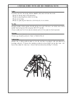
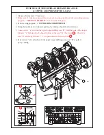
Page 18: ...a HEIGHT AND ALIGNMENT OF CLOTH PRESSER BAR 4a 5 b c 4 7mm...

Page 19: ...of presser foot is in its highest position 5 Turn handwheel towards you and bring feed dog below needle plate 6 Loosen screw c 7 With lever a in its lowered position push cloth presser bar down from...

Page 20: ...12 mm 0 2 R1 Fig 1 Fig 2 Fig 3 5a HEIGHT AND ORIENTATION OF NEEDLE BAR IN RELATION TO THE NEEDLE PLATE HOLES HEIGHT AND ORIENTATION OF NEEDLE BAR IN RELATION TO THE NEEDLE PLATE HOLES 5 b a...

Page 21: ...needle R1 grazes the gauge Fig 2 5 For the orientation of needle bar or needle holder insert new needles in L0 L1 and L2 orientate needle bar so that the needles are centered in the needle plate holes...

Page 22: ...0 in R1 and check height and orientation of needle bar 6 Remove needle plate and machine base 7 Loosen screw b just enough to be able to shift lever c 8 Adjust lever c axially to obtain a clearance of...

Page 23: ...s No 90 in R1 and R2 positions 3 Check height clearance angular position of lower looper 4 Turn the handwheel towardas you and bring needle bar in its lowest position 5 Loosen screws a 6 Shift needle...

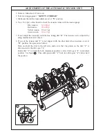
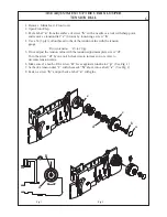
Page 24: ...TIMING OF LOWER LOOPER 8a A B C D b a 5 2mm R1 Fig 1 Fig 2 Fig 3...

Page 25: ...per sketch A 6 If necessary loosen both screws b of lower looper eccentric By means of one screw hold eccentric carefully Fig 1 If in relation to the upper edge of the needle eye the point of the low...

Page 26: ...sition 4 Loosen screw d just enough so that lever e articulates with friction and adjust lever e angularly to obtain a 5 6mm gap between point of looper and the left side of the overlock needle 5 Tigh...

Page 27: ...pivoting axles c and d 5 Clearance Loosen screw e slightly and adjust upper looper to lower looper to obtain a clearance of 0 05 to 0 2mm between them when they pass each other see detailed drawing A...

Page 28: ...11a CHAIN LOOPER ANGULAR POSITION CLEARANCE ORBITAL TIMING CLEARANCE OF CHAIN NEEDLES GUARD 1 5 1 8mm a c Fig 1 d e L2 L0 Fig 2 Fig 5 Fig 3 Motion L2 L0 0 0 05mm 1 0 2 0mm 0 0 05mm Fig 4 e 0 0 1mm f f...

Page 29: ...age 3a 3b for the position of eccentric The eccentric 5 is used for both chain and lower looper timing When adjusting this timing make sure that you also check the adjustment of lower looper stroke Se...

Page 30: ...11c CHAIN LOOPER ANGULAR POSITION CLEARANCE ORBITAL TIMING CLEARANCE OF CHAIN NEEDLES GUARD d c Fig 8 R1 Fig 7 b c g d Fig 6 1 0 1 0mm Fig 9 Motion 2 2 1 1...

Page 31: ...e flush with the needle plate Fig 7 Check if the orbital motion of chain looper from right to left is as per Fig 3 in page 11a If not loosen screws b of eccentric 6 See page 3 and bring eccentric mark...

Page 32: ...the plate b to get the gap 0 5 2 0 as shown in Fig 12 Chain Looper Turn handwheel towards you to bring needle bar to its lowerst position Lift up lever A to disengage chain looper Turn handwheel towar...

Page 33: ...with the following manner In case of too tight stitch formation loosen the screws e and turn adjust c slightly may be about for a small hole in the F direction At the contrary in case of too loose tu...

Page 34: ...gainst needle plate 6 Adjust feed dogs height with eccentric b to touch gauge and tighten screw a Fig 1 7 Turn the handwheel towards you at least 3 complete turns and recheck adjustments 8 Check gap b...

Page 35: ...MOVING CUTTER AND VERTICAL FEED TIMING 14a R1 A a B d c Fig 2 Fig 4 Fig 3 Fig 1 2mm 0 5 0 5mm 1 0 1 5mm...

Page 36: ...s lowest position Then bring up the needle bar to the lower edge of R1 needle eye flush with the needle plate Fig 3 Loosen both screws a bring eccentric mark A close to mark B The distance between mar...

Page 37: ...HORIZONTAL FEED TIMING AGAINST CHAINSTITCH NEEDLE 15a L0 A1 A2 A2 Fig 1 a B 3 A1 A2 Fig 4 2mm A1 A2 Fig 3 B 1 2 3 Fig 2 L0 0 3mm 0 3mm...

Page 38: ...handwheel towards you A2 direction in Fig 4 to bring tip of L0 needle into the paper See Fig 2 1 Turn handwheel towards you further and bring tip of L0 needle flush to the paper See Fig 2 2 Then turn...

Page 39: ...wards you check whether both front and back feed dogs move at equal lengths and the distance between them in motion does not vary as shown on sketch 1 below 4 If not set Stitch Length at 0 5 loosen sc...

Page 40: ...0 2 0 3mm b 0 1 0 3mm 0 1 0 2mm MAX 0 0 05mm POSITION OF FIXED CUTTER AND CUTTING WIDTH DIAL SETTING 17a c a g h f e d j 2mm...

Page 41: ...te edge 7 Re engage moving cutter Turn handwheel towards you and bring moving cutter to its lowest position Make sure if the moving cutter release knob g is not touching the shaft support h the gap be...

Page 42: ...in page 2a 2 Turn the handwheel towards you and bring upper looper thread take up lever a in its highest position 3 Check and make sure that the distance between thread take up lever guide and inside...

Page 43: ...g closing covers If necessary make adjustment in following order Loosen screw a and remove a bracket and push rod c with switch head b Set switch head b upside down by turning push rod c 180 degrees S...

Page 44: ...lever a or swing down needle clamp safety lever c to the right Check if lever b turns on the micro switch 5 If not lower lever a and swing down lever c to the right so that the micro switch is turned...

Page 45: ...Adjustment of the Top Cover Device Model 845 exclusive 21a Fig 1 a b c L0 Fig 2 L2 1 5mm 1 5mm 1 0 mm 1 L1 0 3 0 2...

Page 46: ...oot part No 11636 5 Lower the presser foot 6 Insert the top cover hook into the slot of the holder and fasten screw b 7 Swing down a lever a with triangle thread guide 8 Turn handwheel towards you and...

Page 47: ...Adjustment of the Top Cover Device Model 845 exclusive 21c Fig 3 d e a f Fig 4 Fig 5 4 0 1 0mm 3 0 0 5mm 2 0mm 2 0 0 5mm Fig 6 i g g h...

Page 48: ...the right side edge of the triangle thread guide g comes just below the right side edge of the round thread guide h Those edges must be positioned in parallel See Fig 4 2 3 Tighten screw f 4 Pull out...

Page 49: ...ANNEX TOOLS FOR SETTING SL DF DIALS 1 5 1 0 R2 37 1 0 2 0 Fig 2 84 48 12 10 3 12 2 6 6 Tool A part No 11960 Tool B part No 11961...

Page 50: ...DIALS a 1 For easy adjustment loosen screw a of the upper looper shifting cam first 2 Use tools A and B 3 Insert a tool A into a hole b from the right to the left through holes on Gear Shifting Lever...

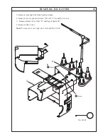
Page 51: ...ANNEX SETTING POSITIONS OF SL DF DIALS b c f d g e 2 1 C B A...

Page 52: ...ure if there is enough space around the area C to install the unit of SL DF dials c Hold on pressing looper follower f from the left side and install the unit of SL DF dials c carefully so that the en...

Page 53: ...d ANNEX SETTING POSITIONS OF SL DF DIALS h i Z k j p SL Dial DF Dial Fig 3 Fig 4 i A n k a Fig 2 view Z view Z...

Page 54: ...tool A goes through 9 Check and make sure if the hook of the looper follower c falls into the V shaped hollow of the upper looper shifting cam b See adjustment of the page F POSITION OF THE PDISPLAY...

Page 55: ...owards you until feed dog moves to far rear position Loosen screw k and move feed bar m back and forth to obtain a clearance F of 0 3 to 0 5 mm Fig 1 Fasten screw k 2 Turn the handwheel towards you un...

Page 56: ...g 1 then check the following points 2 Insert new needles No 90 3 Check and make sure that needles are correctly inserted into the needle clamp 4 Check and make sure that the needle L0 or L1 is not tou...

Page 57: ...2 Fig 3 Fig 4 Fig 5 Fig 6 Red L1 Yellow L2 Red L1 Yellow L2 Blue L0 Yellow L2 Blue L0 Red L1 Yellow L2 Blue L0 Red L1 Yellow L2 ANNEX TROUBLE SHOOTING COVER HEMS irregular loop formation on the chain...

Page 58: ...f L2 needle falls into its needle thread loop Fig 1 2 Check position of chainstitch eccentric 0 5 1 0mm See page 11 for adjustment Check clearance between chain looper and L0 L1 needle If sewing resul...

Page 59: ...ass into neelde thread loops Fabric move forward to the next stitch and chain looper move to the front of the needles Needles go down into the thread triangle and chain looper is moving to the right C...

Page 60: ...ass into neelde thread loops Fabric move forward to the next stitch and chain looper move to the front of the needles Needles go down into the thread triangle and chain looper is moving to the right C...

Page 61: ...M E M O...

Reviews: