background image

User’s Manual No. 980008-001

Rev. B

©1995 Eltron International Inc.

LP/LP+ Series

User’s Manual

Models:

LP2022, LP2042
LP2122, LP2142

Summary of Contents for LP2022

Page 1: ...User s Manual No 980008 001 Rev B 1995 Eltron International Inc LP LP Series User s Manual Models LP2022 LP2042 LP2122 LP2142 ...

Page 2: ......

Page 3: ...inal packing material and mark the RMA number clearly on the outside Ship the equipment freight prepaid to the address listed below Eltron Repair Adminstration 41 Moreland Road Simi Valley CA 93065 1692 805 579 1800 FAX 805 579 1808 COPYRIGHT NOTICE This document contains information proprietary to Eltron International Incorporated This document and the information contained within is copyright by...

Page 4: ...n a commercial environment This equipment generates uses and can radiate radio frequency energy and if not installed and used in accordance with the instructions may cause harmful interference to radio communications However there is no guarantee that interference will not occur in a particular installation Operation of this equipment in a residential area is likely to cause harmful interference i...

Page 5: ...ntrols Indicators 9 Loading Labels or Tags 12 Threading The Label Dispenser 17 AutoSense Gap Sensor Adjustment 19 Cleaning The Print Head 20 Replacing the Printer Memory Backup Battery LP Only 21 Appendix A Troubleshooting 25 Appendix B Supplies and Accessories 37 Appendix C Windows Printer Driver 39 980008 002 Rev B v ...

Page 6: ...vi 980008 002 Rev B ...

Page 7: ...de signed for printing labels tags or continuous receipts with or without bar codes from any DOS or Windows or ASCII based compat ible computer Features Direct thermal printing for reliability Supports over 13 types of bar code sym bologies High resolution print head for sharp graphics and text Download forms fonts and graphics perma nently to removable memory cartridges LP Series 980008 001 Rev B...

Page 8: ...printer Avoid touching the electrical connectors to prevent Electro Static Discharge damage while setting up the printer The discharge of electrostatic energy that accu mulates on the surface of the human body or other surfaces can damage or destroy the print head or electronic components used in this device Getting Started 2 980008 001 Rev B ...

Page 9: ...r LP printer The printer Power Supply Create A Label Tools software disk man ual LP only Printer User s Guide this manual 1 roll of Sample Labels and Spool 1 printer Cleaning Card If any items are missing contact your dealer for replacement parts Getting Started 980008 001 Rev B 3 ...

Page 10: ... in a suitable location preferably on the floor near an electrical outlet Check that the printer power switch is in the OFF 0 position Attach the printer power cable to the jack at the rear of the printer near the power switch Check the label on the power supply for input voltage requirements Attach the power supply line cord to an electrical outlet of the proper volt age The printer and power sup...

Page 11: ...56KB 384KB 512KB The memory cartridge can be damaged if plugged in or unplugged while the printer power is ON 1 Insert the memory cartridge with the label side facing the label roll holder Push firmly to en gage the cartridge Before the additional memory can be ac cessed the printer memory must be reparti tioned Refer to the EPL2 Programming manual for more information on the M com mand Getting St...

Page 12: ... cable from the computer to the DB 9 RS 232 Serial interface connector at the back of the printer For addi tional information on serial cable wiring refer to Appendix A Trouble Shooting When the power switch is moved to the ON 1 position the Power Indicator should light Red indicating that the printer is out of paper If the indicator fails to light refer to Appendix A Trouble Shooting Getting Star...

Page 13: ... floppy disk drive From the DOS prompt enter B INSTALL or A INSTALL if you placed the diskette in drive A Press the Enter key Follow the installation instructions on the screen to install the software Refer to Section 2 Operation for information on loading labels and using your printer Getting Started 980008 001 Rev B 7 ...

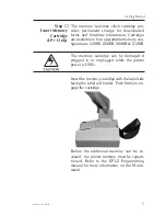
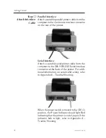
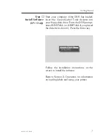
Page 14: ...Getting Started 8 980008 001 Rev B ...

Page 15: ...rear of the unit near the power cord Placing this switch in the 1 ON position will apply power to the printer Place this switch in the 0 OFF position to remove power when you have finished using your printer The printer is equipped with one front panel control switch labeled FEED and one indicator light labeled POWER Refer to Figure 2 1 980008 001 Rev B 9 ...

Page 16: ...Power Switch Figure 2 1 Controls Indicators Power Indicator Feed Control Tension Release Push Back To Release Label Taken Sensor Operation 10 980008 001 Rev B ...

Page 17: ...loading labels in the printer After printing a label holding the FEED control will cause the paper to continuously form feed until the control is released The POWER Indicator When the printer is first switched on the POWER indicator will glow Red If labels are not loaded the indicator will continue to glow Red If labels are loaded the indicator will switch to Green indicating that the printer is r...

Page 18: ... printer causing the label to peel off from the liner Always use high quality Eltron ap proved labels Supplies can be ordered from Eltron by calling 1 800 344 4003 Before loading labels insure that the power supply is connected to a suitable power source and the printer power switch is in the ON 1 position If you should run out of labels while printing Do Not turn the power switch off while reload...

Page 19: ...llows for easier insertion into the feed slot If loading labels place the roll in the top cover so that the end feeds from the top as shown in Figure 2 2 If loading tags place the roll in the top cover so that the end feeds from the bottom as shown in Figure 2 3 Top Feed Figure 2 2 Loading Labels Bottom Feed Figure 2 3 Loading Tags Operation 980008 001 Rev B 13 ...

Page 20: ...n by pushing one or both towards the sides of the printer Step Insert the end of the roll into the feed slot between the guide tabs until resistance is felt approximately 3 Figure 2 4 Open Paper Guides Figure 2 5 Feed Slot Operation 14 980008 001 Rev B ...

Page 21: ...els until the end is visible at the front of the printer Step Press the tension release towards the rear of the printer and center the labels in the slot Adjust the guide tabs so they just touch the edges of the liner Figure 2 6 Press FEED Control Figure 2 7 Center The Labels Operation 980008 001 Rev B 15 ...

Page 22: ...he spindle into the holder slots Step Tap the FEED control 3 times or until the POWER indicator glows Green If you were in the middle of printing labels the printer will automatically resume printing Figure 2 8 Place Roll In Slots Operation 16 980008 001 Rev B ...

Page 23: ...of the Loading Labels pro cedure Step Advance the labels through the printer until at least two full labels approximately 6 are in front of the print head assembly Peel the sec ond and third labels off the backing liner Step Insert the label leader into the peeler slot be tween the peeler bar and the dispenser stopper Peeler Bar Dispenser Stopper Peeler Slot Figure 2 9 Threading The Label Dispense...

Page 24: ...e excess liner through the front until it is tight across the peeler bar Step Activate the Label Taken Sensor by pushing on the top and sliding towards the front of the printer see Figure 2 1 The printer is now ready to dispense automatically peeled labels Push Sensor Out To Activate Figure 2 10 Activate Sensor Operation 18 980008 001 Rev B ...

Page 25: ...ld be activated to adjust the sensitivity of the sensor After loading labels into the printer place the powerswitch in the 0 OFF position Pressand hold the FEED control while placing the power switch in the 1 ON position Release the FEED control when the printer starts feeding labels The POWER indicator will turn off and then switch to Green while the adjustment is being made The printer will adva...

Page 26: ...44 4003 Step Remove any labels loaded in the printer by pressing the tension release towards the rear of the printer and rewinding them onto the roll Step Insert the cleaning card into the feed slot be tween the guide tabs until resistance is felt approximately 3 Step While continuing to gently push the cleaning card into the feed slot press and hold the FEED control until the card is fed through ...

Page 27: ...teps below to replace the battery Battery Replacement Step Turn the printer on with the Memory Cartridge installed for a minimum of 5 minutes This is to prevent data loss while replacing the battery Memory loss will occur if this process is not completed in approximately 5 minutes The discharge of electrostatic energy that accu mulates on the surface of the human body or other surfaces can damage ...

Page 28: ...he old battery out Replace the battery by lifting the battery retaining clip up and inserting the new battery in with the printed side up INSTALL BATTERY WITH PRINTED SIDE UP Improper installation can damage the printer Figure 2 11 Open Cover TOP COVER SRAMS BATTERY TIME DATE CHIP TOP COVER SCREW EPROM BATTERY RETAINING CLIP Figure 2 12 Replace Battery Operation 22 980008 001 Rev B ...

Page 29: ... damage or injury Dispose of the battery according to the manu facturer s instructions Step Re install the cartridge cover and insert the retaining screw Step Re insert the Memory Cartridge into the printer and turn the printer power on WARNING Operation 980008 001 Rev B 23 ...

Page 30: ...Operation 24 980008 001 Rev B ...

Page 31: ...s specifications pricing etc select order a catalog by FAX Internet Web Address http www eltron com eltron e mail techsup eltron com BBS 805 579 3445 The BBS supports data rates up to 28 8 BPS with No Parity 8 data bits and 1 stop bit n 8 1 Communications software should have an ANSI Terminal Mode not MS Win dows Terminal such as Q Modem CompuServe e mail 102251 1164 Customer Service 800 344 4003 ...

Page 32: ...h the thermal side facing up Printing is faded 1 Clean print head with thermal head cleaning card 2 Adjust print speed darkness in software Prints only partial label 1 Label caught on print head Difficult to load labels 1 Label caught on print head or mechanism Printer keeps printing and feed ing labels when it should not be 1 Label caught on label gap sensor inside mechanism 2 Possible software p...

Page 33: ...B 9 Pin DB 9 Pin Female DB 9 to Male DB 9 Cable P N 300017 006 6 or 300017 010 10 N C RxD TxD DTR GND DSR RTS RI CTS Printer Host 1 8 2 3 3 2 4 20 5 7 6 6 7 4 8 5 9 22 DB 25 Pin DB 9 Pin Female DB 25 to Male DB 9 Cable P N 300018 006 6 5 volts at 150 mA for external device e g KDU or scanner 5 Volts TxD RxD N C GND RDY N C N C RDY 5 Volts TxD RxD N C GND RDY N C N C RDY Troubleshooting 980008 001 ...

Page 34: ...stick to the label liner causing the label to peel inside the printer The following pages detail the procedures that must be followed to safely remove a stuck label from the print mechanism When removing a stuck label DO NOT use any type of sharp instrument to scrape the label off the print head or mechanism The best cleaning agent to re move the adhesive residue from the printer surfaces is 91 Is...

Page 35: ...t of the mounting holes Using a 1 Phillips screw driver remove the four screws that secure the top cover Carefully turn the printer right side up and lift off the top cover Use care not to damage the cables leading from the top cover to the main circuit board Disconnect the cables leading from the top cover to the main circuit board noting there positions Troubleshooting 980008 001 Rev B 29 ...

Page 36: ... body or other surfaces can damage or destroy the print head or electronic components used in this device Before touching the print head you should be wearing a grounding wrist strap or should touch a metal part of another piece of equipment that is properly grounded Using a 1 Phillips screwdriver remove the two screws that secure the top print head bracket Remove the bracket and the head tension ...

Page 37: ...ted Do not unplug the print head The cable pro vides ground for E S D protection Carefully clean the print head surface with 91 Isopropyl alcohol and a soft cloth or cotton tipped swab Do not use a sharp or metal instrument to scrape the stuck label from the print head The surface can be easily damaged Print Head CAUTION CAUTION Troubleshooting 980008 001 Rev B 31 ...

Page 38: ...rod drop into the slots on the sides of the carriage Next install the head tension spring aligning it with the two posts on the print carriage Ensure that the label guide near the rear of the print carriage is fully seated Install the top head bracket on top of the spring aligning it with the two posts on the print carriage Insert the two screws removed earlier and tighten to secure the print head...

Page 39: ...n side the mechanism it must be removed from the printer base Remove the three screws that secure the mechanism to the base and the screw that secures the ground wire Carefully lift up the mechanism and disconnect the four cables that lead to the main board noting their positions Troubleshooting 980008 001 Rev B 33 ...

Page 40: ...on both tabs pull the lower sensor assembly away from the mecha nism This provides easy access to the inside of the print mechanism If the clear mylar label guide is damaged it should be replaced Spare parts can be ordered by contacting Eltron at 1 800 344 4003 Troubleshooting 34 980008 001 Rev B ...

Page 41: ...rd Position the print mechanism on the printer base and install the three screws re moved earlier Install the ground wire retaining screw Replace the top cover and secure with the four screws removed earlier Press the four rubber feet into the screw holes Perform the Auto Sense procedure it check for proper operation of the printer Troubleshooting 980008 001 Rev B 35 ...

Page 42: ...Troubleshooting 36 980008 001 Rev B ...

Page 43: ...ccessories Description Part Number Parallel Interface Cable 6 Parallel Interface Cable 10 Serial Interface Cable 6 DB 9 to DB 9 Serial Interface Cable 10 DB 9 to DB 9 Serial Interface Cable 6 DB 25 to DB 9 300016 006 300016 010 300017 006 300017 010 300018 006 Battery Pack Kit 2 battery pack adapter plate Battery Pack Kit 4 battery pack adapter plate 120185 001 120186 001 Cleaning Card 2 single Cl...

Page 44: ...Accessories 38 980008 001 Rev B ...

Page 45: ...utton the printer list is dis played Under the List of Printers select Install Unlisted or Updated Printer When prompted for the location of the driver enter the drive where the diskette is i e A or B Click OK Select the LP driver that represents your printer The printer driver is installed and ap pears in the Installed Printers list in the Printers dialog box Windows For Workgroup Users If you re...

Page 46: ...are accessed through the Printers control panel in the Program Manager Main group Paper Label Size Before creating a label the paper size for the currently loaded labels must be selected in the control panel Setting the proper label size allows the driver to provide accurate printing limits and margin information to other Windows applications in cluding Create A Label Windows Printer Driver 40 980...

Page 47: ...select Options from the printer setup control panel Print Quality Print Density The print darkness or density can be changed by using the Print Quality option If print looks faded when printing at high speed select a higher darkness number for the Print Quality setting If horizontal lines seem to run together select a lower darkness number Print density is also affected by print speed Changing bot...

Page 48: ...41 More la nd Rd Simi Va lle y CA 93065 1692 805 579 1800 ...

Reviews: