

xxxxxxxxxxxxxxxxxx XR44CH ISA GB r1.6 21.11.2016
XR44CH
1/5
Digital controller with defrost and fan management
XR44CH
GENERAL WARNING __________________________________________________________ 1
GENERAL DESCRIPTION ______________________________________________________ 1
CONTROLLING LOADS ________________________________________________________ 1
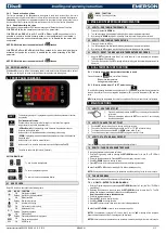
FRONT PANEL COMMANDS ____________________________________________________ 2
MAX & MIN TEMPERATURE MEMORIZATION _____________________________________ 2
DUAL TEMPERATURE FUNCTION _______________________________________________ 2
MAIN FUNCTIONS ____________________________________________________________ 2
PARAMETERS _______________________________________________________________ 3
DIGITAL INPUTS _____________________________________________________________ 4
TTL SERIAL LINE – FOR MONITORING SYSTEMS _________________________________ 4
INSTALLATION AND MOUNTING ________________________________________________ 4
ELECTRICAL CONNECTIONS___________________________________________________ 4
USE THE HOT KEY ___________________________________________________________ 4
ALARM SIGNALS _____________________________________________________________ 4
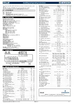
TECHNICAL DATA ____________________________________________________________ 5
CONNECTIONS ______________________________________________________________ 5
DEFAULT SETTING VALUES ___________________________________________________ 5
1.
GENERAL WARNING
1.1
PLEASE READ BEFORE USING THIS MANUAL
This manual is part of the product and should be kept near the instrument for easy and quick
reference.
The instrument shall not be used for purposes different from those described hereunder. It
cannot be used as a safety device.
Check the application limits before proceeding.
Dixell Srl reserves the right to change the composition of its products, even without notice,
ensuring the same and unchanged functionality.
1.2
SAFETY PRECAUTIONS
Check the supply voltage is correct before connecting the instrument.
Do not expose to water or moisture: use the controller only within the operating limits avoiding
sudden temperature changes with high atmospheric humidity to prevent formation of
condensation
Warning: disconnect all electrical connections before any kind of maintenance.
Fit the probe where it is not accessible by the End User. The instrument must not be opened.
In case of failure or faulty operation send the instrument back to the distributor or to “Dixell S.r.l.”
(see address) with a detailed description of the fault.
Consider the maximum current which can be applied to each relay (see Technical Data).
Ensure that the wires for probes, loads and the power supply are separated and far enough from
each other, without crossing or intertwining.
In case of applications in industrial environments, the use of mains filters (our mod. FT1) in
parallel with inductive loads could be useful.
2.
GENERAL DESCRIPTION
Model XR44CH, format 32 x 74 mm, is microprocessor based controller, suitable for applications on
low temperature refrigerating units. It has four relay outputs to control compressor 1 and 2, defrost 1
and 2, which can be either electrical or reverse cycle (hot gas). It is also provided with up to three NTC
or PTC probe inputs, the first one for temperature control, the second and third one, to be located onto
the evaporator, to control the defrost termination temperature on the evaporator 1 and 2.
It allows to program the controller by means the HOT KEY programming keyboard.
3.
CONTROLLING LOADS
3.1
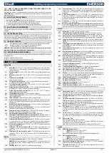
COMPRESSOR
The regulation is performed according to
the temperature measured by the
thermostat probe with a positive
differential from the set point: if the
temperature increases and reaches set
point plus differential the compressor is
started and then turned off when the
temperature reaches the set point value
again.
Time
Temper.
Compr.
SET
ON
In case of fault in the thermostat probe the start and stop of the compressor are timed through
parameters Con and CoF.
3.2
SECOND COMPRESSOR MANAGEMENT
The relay of the second compressor is activated according to the settings of the following parameters.
The 2CC (SEq; HAF), defines how the second compressor is activated.
3.2.1 Sequence activation
With 2CC = SEq the second compressor is activated after a delay counter AC1 ( parameter ). Both
compressor are switched off when the temperature set point is reached.
3.2.2 Dual band activation
With 2CC = HAF the regulation is
changed as follows.
a.
Activation of
compressors
The activation threshold of the first
compressor is (where T is
temperature):
T> SET + Hy
The activation threshold of the
second compressor is (where T is
temperature) :
T>SET+Hy+Hy2
The second compressor is activated in any case only if the AC1 timer has already expired, where AC1
is the delay between the activation of two compressors
b.
Deactivation of compressors
The second compressor is switched off when the temperature drops below
T <SET + Hy
The first compressor is turned off when:
T<SET
ROTATION
Once both the compressors are switched off, the activation order of the 2 compressors is reversed in
order to balance the working hours.
A cycle is considered as completed even if only one compressor is switched on and off: that is, when
the temperature exceeds the first activation threshold, (SET + HY) and then latter returns below the
value of the set point (SET).
STALL PREVENTION
The Mon parameter defines the maximum time a single compressor can run continuously. When the
Mon timer expires the other compressor is activated, to increase capacity and therefore to reduce the
temperature, both the compressors are switched off at the same time when the SET point is reached
3.3
DEFROST
3.3.1 THE PRE-DEFROST CYCLE
A pre-defrost cycle, to cool deeper the goods before the defrost can be managed.
If it is enabled the temperature set point (SET) becomes: SET+Hd1 for Ht1 mins, then the defrost
starts.
The pre-defrost cycle cannot be performed if the defrost is started manually by keyboard.
3.3.2 THE POST- DEFROST CYCLE
After defrost and dripping time, a post defrost cycle can be managed.
If it is enabled the temperature set point (SET) becomes: SET+Hd2 for Ht2 mins, then the standard
regulation starts..
If enabled, the post defrost cycle si always done.
3.3.3 DEFROST MODES
Two defrost modes are available through the tdF parameter: defrost through electrical heater
(tdF=EL) and hot gas defrost (tdF=in). In this case by the parameter StC (0÷15min) the compressor
can be stopped before the defrost. The compressor is stopped after the pre-defrost cycle.
Other parameters are used to control the interval between defrost cycles (idF), its maximum length
(MdF) and two defrost modes: timed or controlled by the evaporator’s probe (P2P).
At the end of defrost dripping time is started, its length is set in the Fdt parameter. With Fdt=0 the
dripping time is disabled.
3.3.4 SECOND EVAPORATOR CONTROL AND EVAPORATORS CYCLING
WITH HOT GAS DEFROST
With tdF = ALt a hot gas defrost with double evaporator is managed. The 2 evaporators are
alternated according to the following indications:
a.
After IdF the COMP+DEF1 are activated
b.
After IdF the COMP+DEF2 are activated
c.
After IdF the COMP+DEF1 are activated
3.4
CONTROL OF EVAPORATOR FANS
The fan control mode is selected by means of the FnC parameter:
FnC=C_n, fans will switch ON and OFF with the compressor and not run during defrost.
FnC=o_n, fans will run even if the compressor is off, and not run during defrost.
After defrost, there is a timed fan delay allowing for drip time, set by means of the Fnd parameter.
FnC=C_Y, fans will switch ON and OFF with the compressor and run during defrost.
FnC=o_Y, fans will run continuously also during defrost.
An additional parameter FSt provides the setting of temperature, detected by the evaporator probe,
above which the fans are always OFF. This is used to make sure circulation of air only if his
temperature is lower than set in FSt.
3.4.1 Forced activation of fans
This function managed by the FCt parameter is designed to avoid short cycles of fans, that could
happen when the controller is switched on or after a defrost, when the room air warms the evaporator.
How it works: if the temperature difference between evaporator probe and room probe is higher than
the FCt parameter value, fans will be switched on. With FCt=0 the function is disabled.
3.4.2 Cyclical activation of the fans with compressor off.
When FnC=C-n or C-Y (fans working in parallel with the compressor), by means of the Fon and FoF
parameters the fans can carry out on and off cycles even if the compressor is switched off. When the
compressor is stopped the fans go on working for the Fon time. With Fon=0 the fans remain always
off, also when the compressor is off.


