background image

Liebert

®

 NXC


f

rom 10 to 20k

VA

User Manual

AC Power for

Business-Critical Continuity

Summary of Contents for Liebert NXC

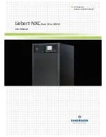
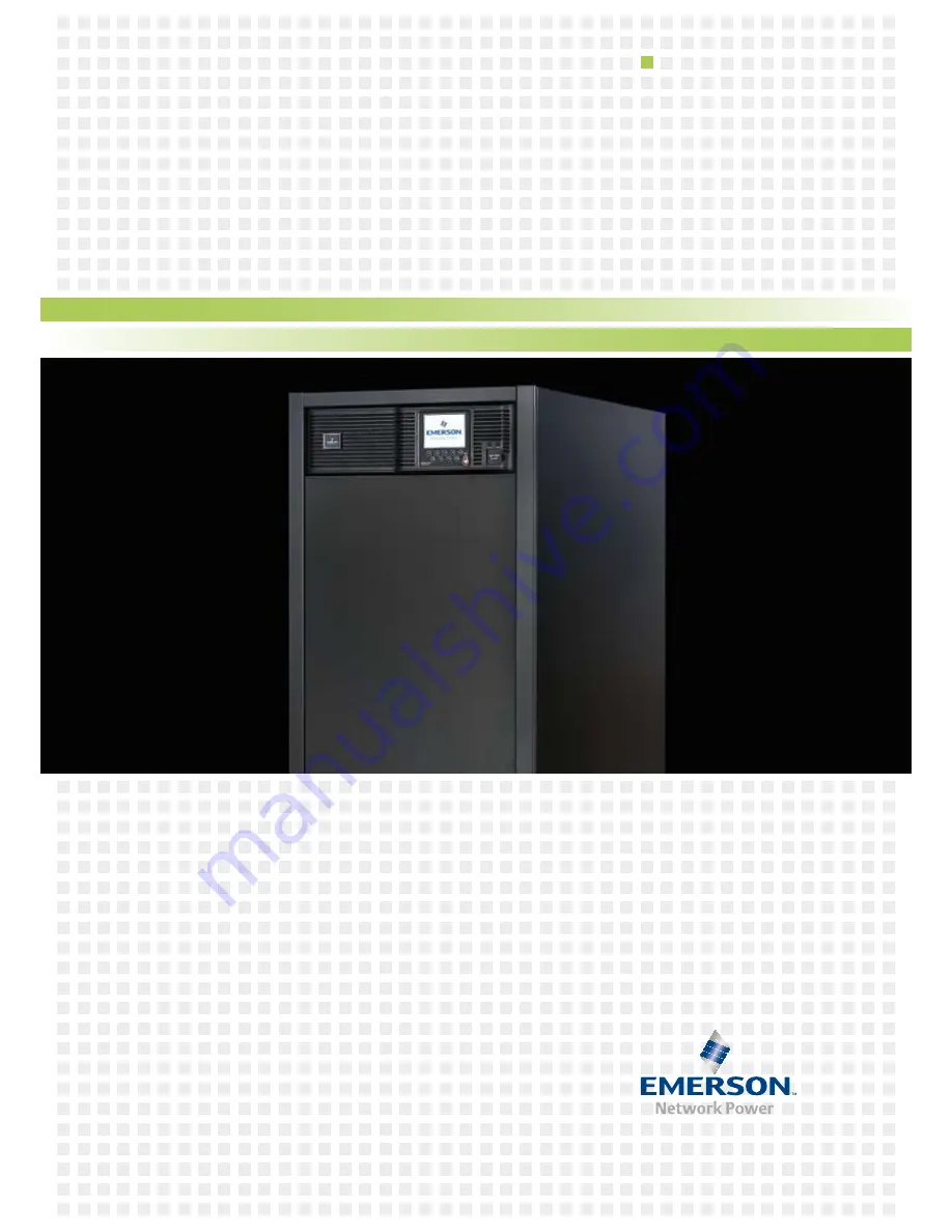
Page 1: ...Liebert NXCfrom 10 to 20kVA User Manual AC Power for Business Critical Continuity ...

Page 2: ...Liebert NXC 10 15 20kVA UNINTERRUPTIBLE POWER SUPPLY USER MANUAL 10H52188UM60 rev 2 ...

Page 3: ... or similar methods even of parts are reserved Offenders will be liable for damages All rights including rights created by patent grant or registration of utility model or design are reserved Delivery subject to availability Right of technical modification reserved Liebert NXC may differ from the one displayed on the front cover ...

Page 4: ... 2 2 Environmental Requirement 20 3 2 3 Installation Tools 21 3 3 External protection devices 22 3 3 1 Rectifier And Bypass Input 22 3 3 2 Battery Input for external Battery 24 3 4 Connecting Power Cables 24 3 4 1 Connecting I O Cables 25 3 4 2 Connecting and Installing External Battery 30 3 5 Single UPS Commissioning 31 3 5 1 Check Before Power On 31 3 5 2 Single UPS Parameters Setting 31 3 5 3 N...

Page 5: ...n 53 6 4 EPO 53 6 5 Auto Restart 53 6 6 UPS Reset 54 6 7 Language Selection 54 6 8 Changing Current Date And Time 54 6 9 Control Password 54 CHAPTER 7 COMMUNICATION 55 7 1 Installing Intellislot cards 55 7 1 1 Intellislot card Port 55 7 2 Connection cables for dry contact port and opto coupled port 55 7 3 Connecting USB Communication Cables 57 CHAPTER 8 MAINTENANCE 58 8 1 Fan Maintenance 58 8 2 Ba...

Page 6: ...tput immunity to grid interference thus suitable for use in areas with unstable mains supply High power density Full digital control technology based on digital signal processor DSP to achieve high system reliability with self protection and fault diagnosis functions Intelligent battery management to extend the battery life Operation and display panel with both LCD and LED indication to help you l...

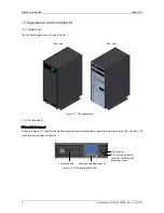
Page 7: ...view Figure 1 1 UPS appearance 1 3 2 Components UPS module front panel As shown in Figure 1 2 the UPS module front panel provides ventilation holes operation and display panel LED indicators DIP switch and battery cold start button Figure 1 2 UPS module front panel Ventilation hole Operation and display panel LED indicator DIP switch and battery cold start button with protective cover ...

Page 8: ...contact ports opto coupled ports USB port and ventilation holes The SIC SNMP card in the Intellislot cards port is optional it is sold separately Figure 1 3 UPS module rear panel Figure 1 4 User dry contact and opto coupled connectors Note Non authorized personnel are prohibited from opening the UPS chassis cover Parallel port LBS port Intelligent card port with protective cover Dry contact port a...

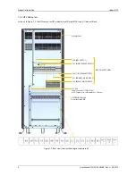
Page 9: ...le Input Output MCBs and I O terminal block Figure 1 5 Rear view terminal housing cover removed INPUT OUTPUT MCBs UPS MODULE I O TERMINAL BLOCK Screw terminals M6 QS4 UPS OUTPUT QS3 MAINTENANCE BYPASS QS6 7 INTERNAL BATTERY QS1 PRIMARY MAINS INPUT QS2 BYPASS MAINS INPUT FU1 FU2 Supply fuses for LIFE AC 230V max cables cross sectional area 2 5mm2 ...

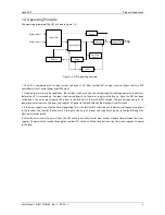
Page 10: ...verter via the rectifier PFC section The inverter then converts DC power into pure sine wave AC power and supplies AC power to the load through the electronic transfer switch 3 If the mains supply is outside the normal operating limits the rectifier PFC circuit boosts the battery voltage and supplies it to the inverter The inverter then converts it into pure sine wave AC power and supplies AC powe...

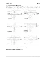
Page 11: ...atic diagrams of Normal mode Bypass mode Battery mode Maintenance Bypass mode ECO mode and FRC mode are shown in Figure 1 7 Figure 1 7 Operation schematic diagram For the LED indicators introduced in this section refer to 5 1 1 Bypass input Mains input Normal mode Output Bypass input Mains input Bypass mode Output Bypass input Mains input Maintenance Bypass mode Output Bypass input Mains input Out...

Page 12: ...to ensure the adequate backup time for battery 2 The battery cold start can also be used to start the UPS from the Battery charged mode upon mains failure Therefore the battery power can be used independently for improving the system availability to some extent 1 5 4 ECO Mode For Single UPS System Only In ECO mode the load is powered by bypass when the bypass voltage is normal and the load is powe...

Page 13: ...eaker and the power to the load is uninterrupted The maintenance bypass Miniature Circuit Breaker is located on the rear panel of the UPS device and the capacity meets the requirements of total load capacities Note If the UPS has a malfunctions and can not work normally please get in touch with the nearest Emerson branch office or local service center It is prohibited to repaire by yourself as the...

Page 14: ... when battery cabinets are used with original accessories If alternative batteries are used you must ensure that the applicable EC directives are met and declare conformity 2 2 Safety Take special care when working with the batteries associated with the UPS When all the blocks are connected together the battery string voltage can be up to 460 Vdc This is potentially lethal Please follow the precau...

Page 15: ...re working on the batteries and ensure that the tools for example wrenches are insulated Failure to do so may result in battery burning explosion human death or injury 8 Do not dismantle modify or damage the battery This may result in a battery short circuit electrolyte leakage or even injury 9 Clean the battery enclosure with a damp cloth To avoid any static or arcing do not use dry cloths or dus...

Page 16: ...using shielded battery cables between the UPS cabinet and the battery cabinet The shielding must be connected to both the UPS and the battery cabinets 3 Make the ground connections PE 4 When multiple battery strings are used they must be connected in series and then in parallel Before applying load and commencing power up be sure to measure the total voltage of the battery strings and make sure th...

Page 17: ...attery Liebert NXC ARRANGE THE BATTERIES AND CONNECT THEM AS ILLUSTRATED IN Figure 2 1 Figure 2 1 Internal Battery Cable Connection BATTERY SHELF BATTERY 8 BATTERY 7 BATTERY 6 BATTERY 5 BATTERY 4 BATTERY 3 BATTERY 2 BATTERY 1 XBS TOP VIEW FRONT ...

Page 18: ...ed on male connector of battery shelf disconnect the female connector in order to connect the XBS male connector of the battery shelf to the female connector on the UPS N B The 3rd and 4th strings may also be installed in the field during the initial installation BATTERY STRING 1 BATTERY STRING 2 BATTERY STRING 3 BATTERY STRING 4 XBS1 XBS2 XBS3 XBS4 XBS5 XBS6 XBS7 XBS8 XBS9 XBS10 XBS11 XBS12 XBS13...

Page 19: ...llution control Storage transportation use and disposal of batteries must comply with the national and local laws and regulations on dangerous waste disused battery pollution prevention and other standards In accordance with the relevant national regulations disused lead acid storage batteries must be recycled and must not be disposed of by other methods Illegal dumping or any other improper dispo...

Page 20: ...ance for transportation damage If any problem is found please notify the carrier immediately 2 Check the accessories and models against the below delivery list If any problem is found please notify the dealer immediately Safety manual User manual Test bulletin Insulating material 28010935 Copper busbar kit 21500904 1x connector 3 PIN pitch 3 81mm 14120115 3x connector 2 PIN pitch 3 81mm 14120116 7...

Page 21: ...ng temperature compliant with the specifications see Table 9 2 for details 3 2 2 Environmental Requirement UPS room The UPS is designed for indoor installation which should be installed in a clean and well ventilated environment so as to keep the ambient temperature within the specifications The internal fans provide the forced air cooling for the UPS Cooling air enters the UPS through the ventila...

Page 22: ...uced by 50 if the battery temperature in operation exceeds 40 C the battery life will be decreased exponentially In general the ideal ambient temperature of the battery is 15 C 25 C The battery should be kept away from heat and ventilation holes When the UPS uses an external battery you must install a battery protective device such as fuse or circuit breaker near to the battery and use the shortes...

Page 23: ...configurations they may trip unexpectedly In order to guarantee correct distribution in the neutral cables installation personnel shall make sure that the lengths of the cables are as equal as possible However if the bypass lines lead from sources that are electrically isolated from each other a differential protection device may be installed on each line In this case and in cases when the load is...

Page 24: ...r RCCB must be sensitive to the DC unidirectional pulse level A in power distribution network but insensitive to the transient current pulse as shown in Figure 3 3 respectively Figure 3 3 RCCB symbols When using the earth RCD in split bypass system or parallel system the RCD should be installed at the upstream input power distribution terminal to avoid generating false alarms The earth leakage cur...

Page 25: ...max allowable voltage drop is 4Vdc Do not ring the cables so as to avoid increasing the electromagnetic interference EMI 1 The mains current input of the rectifier and bypass 2 Non linear load switch mode power affects the neutral cable design of output and bypass The neutral cable current may exceed the rated phase current in general 1 732 times as large as the rated current not applicable when 3...

Page 26: ...lit bypass configuration 3 in 1 out common source configuration 3 in 1 out split bypass configuration Self distribution The four I O cable connection procedures of the self distribution are as follows 3 in 3 out common source configuration factory default 1 Connect the live lines input phase L1 input phase L2 and input phase L3 N line and PE line respectively to the I O terminal block U1 V1 W1 and...

Page 27: ...1 mains input phase L2 and mains input phase L3 N line and PE line respectively to the I O terminal block U1 V1 W1 and N1 and PE terminals of the UPS 3 Connect the live lines bypass input phase L1 bypass input phase L2 and bypass input phase L3 and N line respectively to the I O terminal block U2 V2 W2 and N2 terminals of the UPS 4 Connect the live lines output phase L1 output phase L2 and output ...

Page 28: ... the following section Changing power distribution mode 2 As shown in Figure 3 7 attach the self adhesive insulating film accessory on the copper shorting bar 10 and insert the buckles into the corresponding holes on the copper shorting bar 10 Assembling Completed status Insulating film Copper shorting Buckle bar 10 Figure 3 7 Attaching the insulating film to the copper shorting bar 10 3 As shown ...

Page 29: ...common source configuration Change the power distribution mode of the main UPS to 3 in 1 out according to the steps described in the following section Changing power distribution mode Continue the following input and output power cable connection and power on commissioning after confirming that the change has been successful 1 Confirm that the power distribution mode of the main UPS has been chang...

Page 30: ... to the copper shorting bar 8 6 Connect the bypass input N line to the copper shorting bar 4 with N1 and N2 terminals of the UPS I O terminal block 7 Connect the output L line N line and PE line respectively to the copper shorting bar 5 copper shorting bar 4 with two N3 terminals and the other screw hole of the copper shorting bar 10 of the UPS I O terminal block Warning Before the commissioning e...

Page 31: ...n power on the system again enter this menu to confirm the setting is valid 4 Power off the system completely and replace the EPO jumpers of the dry contact port 4 and remove the main input cable From 3 in 1 out to 3 in 3 out 1 Remove all copper shorting bars shown in Figure 3 8 and Figure 3 9 of the 3 in 1 out system connect the main input cables only It is prohibited to connect the bypass input ...

Page 32: ... Table 3 4 The other settings can be done only by service software ParamSet Table 3 4 Single UPS parameters setting Parameters Default value Parameters setting ParamSet Display Setting Single Group Batt Cap 0014 Set the parameter according to the actual battery capacity x Battery Cells Number 32 Set the parameter according to the actual battery number x Equalize Charge Allowed Enabled Set the para...

Page 33: ...le x Parallel Requisite Units Set the parallel units 1 x Parallel Redundant units Set the redundant units 0 x ECO Mode Working in the normal mode or ECO mode Normal x Output Frequency Level Set the output frequency 50Hz x Output Voltage Level Set the output voltage level 400V x LBS Function Set the LBS function NONE SLAVE or MASTER can be selected NONE x Command password 12345 12345 x Protocol Set...

Page 34: ...ay attention to the personnal safety to avoid electric shock Note whether it is safe to feed power to load 2 LCD displays the self test screen the fault indicator red and inverter indicator green are on at the same time for about 5 seconds After the self test UPS enters the bypass state the fault indicator turns on and the buzzer beeps for 1 second 3 The rectifier runs in normal state about 30 sec...

Page 35: ...ual utilization of all UPS units and compliance with relevant wiring regulations the following requirements must be met 1 All single UPS must have the same capacity and must be connected to the same bypass source 2 The bypass input power and rectifier input power must be connected to the same neutral line input terminal 3 If a residual current detector RCD is required it must be set correctly and ...

Page 36: ...tallations an external bypass rated for the total system load must be installed and the UPS internal maintenance bypass must be locked to prevent it from being operated When planning and installing the system the power cables between input distribution and the Bypass and rectifier must be the same length 10 The same applies to the power cables between the UPS outputs and the parallel connection po...

Page 37: ... mC bB mB bA mA bN mN oN oN oA oB oC PE PE DB9 male port DB9 female port Figure 4 2 Cable connection schematic diagram of 3 1 parallel system Note 1 The Emerson parallel cables must be used for the parallel system 2 The parallel communication fault occurs when carrying out the parallel commissioning check whether the connection of the parallel cables is correct and whether the pin1 pin9 are connec...

Page 38: ...endently the battery cable connection of each UPS in parallel system is the same as that of the single UPS refer to 3 4 2 The schematic diagram of battery strings in 1 1 parallel system when using battery strings independently is shown in Figure 4 3 Note Make sure that the LCD settings are correct when using the battery strings independently refer to 4 4 2 for details Figure 4 3 Connection princip...

Page 39: ...r on the system set each single UPS to shared battery string configuration through the Service Software Settings Shared Battery from each UPS unit set the Service Software Settings Battery Cells Number and Single Group Batt Cap from each UPS unit and each UPS unit setting must be the same Note 1 For the parallel system used the shared battery strings make sure that the Service Software settings ar...

Page 40: ...d to start the inverter Set the parallel parameters according to Table 4 2 Table 4 2 Parallel parameters setting Parameters Default value Parallel parameters setting ParamSet Display Setting Single Group Batt Cap 0014 Set the parameter according to the actual battery capacity x Battery Cells Number 32 Set the parameter according to the actual battery number x Equalize Charge Allowed Enabled Set th...

Page 41: ...rking normally turn off the UPS 8 Repeat the preceding step 1 step7 to power on and commission the other UPS respectively Note Carry out the parallel commissioning after each UPS is working normally Confirm that each UPS has been powered on and working normally commission the parallel system the specific procedures are as follows 1 Close the external output MCB and input MCB and the corresponding ...

Page 42: ...See 3 3 for details of installation and type selection 4 5 3 Connecting Power Cables In double bus system refer to 3 4 and 4 3 to select the power cables for single UPS and parallel system respectively The bypass input power and mains input power must use the same neutral input terminal The leakage current protective device should be installed before the input terminal 4 5 4 Connecting LBS Cables ...

Page 43: ...Using the double bus system formed by 1 1 parallel system as an example set System Configuration to Parallel Parallel requisite units to 1 Parallel Redundant Units to 1 For the master system set LBS Function to MASTER For the slave system set LBS Function to SLAVE Ensure that the setting for 3 Phase Output or 1 Phase Output of each single UPS in the double bus system is same as shown in Figure 4 8...

Page 44: ...RM CLEAR EPO Figure 5 1 Operation and display panel 5 1 1 LED Indicators The LED indicators are composed of inverter indicator and fault indicator Table 5 1 gives the indicators description Table 5 1 Description of LED indicators Indicator Color State Meaning Inverter indicator Green On Load power is supplied by the inverter Blinking Inverter on starting up synchronizing or standing by ECO mode Of...

Page 45: ... buzzer 5 1 4 LCD And Menu Buttons The operation and display panel is composed of an LCD and five menu buttons F1 F2 F3 F4 HELP Table 5 4 gives the menu buttons function description Table 5 4 Menu buttons function description Button F1 F2 F3 F4 HELP Function 1 HOME ESC Escape Left Right Enter Function 2 Up Down LCD provides you with the user friendly interface and the 320 240 dot matrix image disp...

Page 46: ... 0 0 0 0 Power factor 0 00 0 00 0 00 System information window Data window Menu window Keypad window Figure 5 3 Primary screen The current icons on top of the F1 F4 and HELP menu buttons give the explanations of each button From any menu in the primary screen pressing the F1 button will return to the Output menu For details about the primary screen refer to 5 3 5 2 3 Default Screen During the UPS ...

Page 47: ...ltage V Line voltage Power factor Power factor Bypass L N voltage V Phase voltage Frequency Hz Bypass frequency L L voltage V Line voltage Output L N voltage V Phase voltage L N current A Phase current Frequency Hz Output frequency L L voltage V Line voltage Power factor Power factor Load Sout kVA Sout Apparent power Pout kW Pout Active power Qout kVAR Qout Reactive power Load level The percentage...

Page 48: ... level x LBS Function Set LBS function Option NONE SLAVE or MASTER x Command password You can change the command password Default 12345 x Protocol Set the communication protocol of the UPS x 3 in 3 out 3 in 1 out Set the output system 3 in 3 out or 3 in 1 out This setting can only be carried out after the EPO operation After the setting you must power off the system and confirm that the system act...

Page 49: ...on the system again after the wiring is changed according to the settings 5 5 UPS Alarm Message List Table 5 8 gives the UPS alarm message list based on the Event and Records menus Table 5 8 UPS alarm message list Alarm message Description Inverter comm fail Internal communication failure between the monitoring board and the inverter Rectifier comm fail Internal communication failure between the m...

Page 50: ...asurement Inverter fault Inverter output voltage beyond limits Load transfers to bypass Inverter overtemp The temperature of the inverter heat sink is too high to keep the inverter running This alarm is triggered by the signal from a temperature monitoring thermostat on the inverter bridge heat sink The alarm is cleared after about 20 minutes the inverter will start again automatically The UPS wil...

Page 51: ...RM CLEAR Turn on fail Inverter failed to turn on manually The reason may be the invalid operation maintenance bypass breaker closed or DC bus or rectifier not ready Alarm silence cancle Press FAULT CLEAR or ALARM CLEAR Bypass mode The UPS is in Bypass mode Normal mode The UPS is in Normal mode Battery mode The UPS is in Battery mode Check UPS output 1 Whether the EPO terminal is on the dry contact...

Page 52: ...start up refer to 3 5 3 and 3 5 4 for details For the detailed information of the parallel UPS refer to 4 4 3 6 2 Transfer Procedures Between Operation Modes Note The Inverter operation mode include Normal mode mains inverter and Battery module battery inverter 6 2 1 Transfer From Normal Mode To Battery Mode In the event of mains failure the UPS will transfer to Battery mode If you wish to transfe...

Page 53: ...ypass Mode To Inverter Mode After UPS maintenance you can use this procedure to transfer the load from the maintenance bypass to the inverter Warning As no auxiliary contact information of the maintenance bypass MCB QS3 is introduced into the UPS UPS operation restoration after maintenance must be done strictly following this procedure Failure to observe this may cause damage to the equipment 1 Cl...

Page 54: ...itch off the UPS in emergency conditions such as fire flood The system will turn off the rectifier inverter and stop powering the load immediately inverter and bypass output included and the battery stops charging or discharging If the mains input is present the UPS control circuit will remain active however the output is opened To remove all mains power from the UPS the external input switch shou...

Page 55: ...e available in 17 languages English German Italian French Spanish Portuguese Chinese Japanese Swedish Russian Polish Czech Turkish Arabic Dutch Finnish and Norwegian Procedures for selecting the language 1 From the Output menu press F3 or F4 left or right arrow to select the Language menu 2 Press F5 Enter to move the cursor to the data window of the LCD 3 Use F3 and F4 up and down arrow to select ...

Page 56: ... 2 3 4 and 5 The pin layout of each port is shown in Figure 7 2 and the port description is shown in Figure 7 1 Cable cross sectional are 0 1 1 5mm2 12V 12V 12V SALARM GND On_battery GND On_bapass GND Epo_NC 12V 12V Epo_IN BFP_o BFP_s BFP_c Figure 7 2 Pin layout of dry contact and opto coupled ports Port n Description Signal type Who supply the power of signal Rated voltage Rated current 1 Output ...

Page 57: ...ll stop the rectifier inverter and static bypass but it cannot disconnect the UPS mains input inside If you want to disconnect the UPS completely just disconnect the upstream input MCB when generating the EPO In emergency conditions close the REPO switch prepared by users to shut down the rectifier and inverter and the UPS is powered off In normal condition the REPO switch cannot cut off the UPS i...

Page 58: ...h before restart the UPS 7 3 Connecting USB Communication Cables The USB port is located on the rear panel of the UPS as shown in Figure 1 3 The USB port can connect the monitoring software The methods to connect the communication cable are as follows Insert one end of the USB communication cable to the USB port see Figure 1 3 on the rear panel of the UPS and connect the other end to the USB port ...

Page 59: ...months at high ambient temperature Note 1 Make sure that the safety equipment are complete and that the function is normal especially that the settings of the battery management parameters are normal 2 Measure and record the internal temperature of the battery room 3 Check whether the battery terminals are damaged or hot and whether the cases and the covers are damaged If liquid leakage and damage...

Page 60: ... find out the reason such as operator intervention overload internal fault and so on 3 Check if the battery is discharging When AC mains is normal the battery should not discharge if the UPS operates in Battery mode you should find out the reason such as mains failure battery test operator intervention and so on 8 5 Checking UPS Functions Note UPS functional check procedures may cause power interr...

Page 61: ...le 9 2 Environmental Characteristics Item Unit Rated power kVA 10 15 20 Noise within 1 m from the front dBA 58 58 58 Altitude m 2000 derating according to GB T3859 2 when higher that 2000 m Relative humidity RH 5 95 non condensing Operating temperature C 0 to 40 battery life is halved for every 10 C increase above 20 C Storage and transport temperature for UPS C 20 to 70 Recommended battery storag...

Page 62: ... voltage Vdc Nominal 384 VRLA float charge is 436 V range 300 to 576 Quantity of lead acid blocks Nominal 32 Other possible values 30 34 36 38 40 Float voltage V cell VRLA 2 27 selectable between 2 2 V cell and 2 3 V cell Constant current and constant voltage charge mode Ripple voltage V float 1 41 Ripple current C10 5 Boost voltage V cell VRLA 2 35 selectable between 2 3 V cell and 2 4 V cell Con...

Page 63: ...ectable by commissioning engineer Note that the system frequency can be changed only when the UPS is on bypass It is strictly prohibited to change the system frequency when the UPS is on inverter 3 IEC 62040 3 annex E crest factor 3 1 9 7 Electrical Characteristics Bypass Input Table 9 7 Bypass Input Item Unit Rated power kVA 10 15 20 Rated AC voltage1 Vac 380 400 415 three phase five wire sharing...

Page 64: ...0 15 20 Overall efficiency Normal mode double conversion 100 load 94 2 94 1 94 0 66 load 93 9 94 2 94 5 33 load 91 3 93 7 93 9 ECO Mode 98 Battery mode 92 5 92 8 93 Heat losses air exchange Normal mode kW 0 55 0 84 1 15 Eco mode kW 0 18 0 28 0 37 No load kW 0 24 Maximum forced air cooling front intake rear exhaust L sec 208 Note 400Vac input and output battery fully charged full rated linear load ...

Page 65: ...lel system See Table 10 2 for cable description Refer to 4 3 2 for the methods to connect the parallel cables Table 10 2 Description of the communication cable Type Name Description Appearance 00B46158P77 Communiation cable For N 1 parallel system N 1 communication cables are needed For example two communication cables are needed in 1 1 parallel system three communication cables are needed in 2 1 ...

Page 66: ...ility Figure 10 2 UPS with input isolating transformer 10 5 Liebert NXC Output Transformer Version This UPS includes an isolation transformer at the UPS output This transformer is installed in place of the batteries and provides electrical isolation between the UPS output and the load Figure 10 3 UPS with output isolating transformer WARNING remove the connection between neutral and earth on the t...

Page 67: ... Electromagnetic compatibility EOD End of discharge EPO Emergency power off LCD Liquid crystal display LBS Load bus synchronizer MCB Miniature circuit breaker PE Protective earth RCCB Residual current circuit breaker RCD Residual current detector RFI Radio frequency interference SCR Silicon controlled rectifier STS Static transfer switch UPS Uninterruptible power system VRLA Valve regulated lead a...

Page 68: ...esign and manufacturing of environment friendly products It will reduce and eventually eliminate the harzardous substances in the products through unremitting efforts in research However limited by the current technical level the following parts still contain hazardous substances due to the lack of reliable substitute or mature solution 1 All solders in the products contain lead 2 Copper alloy con...

Page 69: ...a Leonardo Da Vinci 16 18 Zona Industriale Tognana 35028 Piove di Sacco PD Italy Tel 39 049 9719 111 Fax 39 049 5841 257 marketing emea emersonnetworkpower com Via Fornace 30 40023 Castel Guelfo BO Italy Tel 39 0542 632 111 Fax 39 0542 632 120 enquiries chloride emerson com United States 1050 Dearborn Drive P O Box 29186 Columbus OH 43229 Tel 1 614 8880246 Asia 7 F Dah Sing Financial Centre 108 Gl...

Reviews: