background image


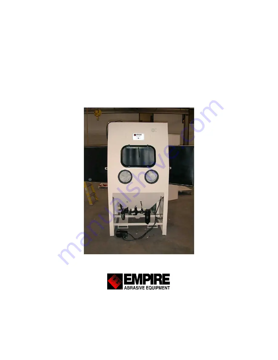
Operating Instructions 

for the 

ProFormer

TM

 Cabinet System 

Pressure and Suction 


2101 West Cabot Boulevard 

Langhorne, PA 19047-1893 

www.empire-airblast.com 


Summary of Contents for ProFormer

Page 1: ...Operating Instructions for the ProFormerTM Cabinet System Pressure and Suction 2101 West Cabot Boulevard Langhorne PA 19047 1893 www empire airblast com...

Page 2: ...ot Boulevard Langhorne PA 19047 1893 Phone 215 752 8800 Fax 215 752 9373 Empire equipment should be properly maintained per the operating instructions For peak performance of your equipment use only g...

Page 3: ...Empire Abrasive Equipment Company Operating Instructions for the ProFormerTM Cabinet System Suction and Pressure Empire Abrasive Equipment Company 10 06 06 Page 3...

Page 4: ...stment 15 3 3 Reclaimer Adjustment 16 4 0 Suggestions for Efficient Blasting 19 4 1 Media Selection and Use 19 4 2 Blast Pattern 20 4 3 Changing the Media 21 4 4 Pneumatic Controls 22 4 5 Helpful Hint...

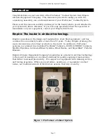
Page 5: ...of air blast equipment and has continued as an industry leader of more than 50 years Today Empire produces the most extensive line of air blast products in the world In addition to ProFormer systems o...

Page 6: ...ystem to the installation location Step 3 Insure there is adequate space on both sides of the cabinet for full opening of part loading unloading and maintenance access doors PF3642 cabinets require 37...

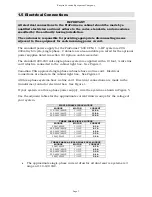
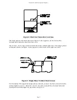
Page 7: ...single phase cabinets have no line cord Electrical connections are made in the cabinet light box See Figures 3 All three phase systems have no line cord Electrical connections are made in the transfor...

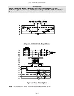
Page 8: ...re line cord is located above the cabinet light box The single phase schematic shown in Figure 4 also appears on the back of the light box cover Figure 3 Single Phase Terminal Board Access For Canadia...

Page 9: ...wer check that the voltage requirements of your ProFormer system are consistent with the voltage available at the installation site Figure 4 220 240 Volt Single Phase Figure 5 Three Phase Option Note...

Page 10: ...si 60 psi 80 psi 100 psi nozzle 1 8 air jet 12 17 21 26 5 16 nozzle 5 32 air jet 19 27 34 42 3 8 nozzle 3 16 air jet 29 39 50 62 7 16 nozzle 7 32 air jet 38 52 66 80 AIR REQUIREMENTS SCFM FOR PRESSURE...

Page 11: ...pressure regulator to 40 psi Check that the optional fan silencer is fully opened Step 4 Turn the cabinet snap switch to the On position The cabinet lights will illuminate and the dust collector fan w...

Page 12: ...component access door After loading the media reinstall the reclaimer door and insure an airtight seal Method 2 With the snap switch ON and the dust collector running load media through the media loa...

Page 13: ...t treated Step 2 Step on the foot treadle to start the blast After a few seconds the abrasive flow will stabilize and you will be ready for blasting Step 3 Do not pump the foot treadle It will decreas...

Page 14: ...and protective equipment when disposing of collector waste Dispose of this waste properly WARNINGS Explosive Dust Explosive dust is generated from blast media removed coatings and substrates An extre...

Page 15: ...re System Media Flow Adjustment The ProFormer pressure blast system is supplied with the patented Sure Flo Media Regulator which is installed at the bottom discharge port of the pressure vessel By rot...

Page 16: ...ted The slot pattern around the reclaimer body has one slot omitted The joined ends of the tuning band must be located over the area of the omitted slot NOTE Dust collectors require a coating of dust...

Page 17: ...the dust collector waste additional reclaimer tuning band adjustment may be required Follow Steps 9 through 13 Step 9 Adjust the tuning band back to the previous reference mark on the reclaimer body...

Page 18: ...rage hopper or pressure vessel This accumulation leads to inefficient blasting Conversely too much secondary air will cause useful media to be carried to the dust collector and be wasted To avoid thes...

Page 19: ...to 80 Mesh 100 to 300 Mesh 25 to 180 Mesh 200 to 300 Mesh G 16 to G 50 G 80 to G 200 S 390 to S 170 S 110 to S 70 Any Size Suction R R R R NR R NR R R Pressure R R R R NR R NR R R R Recommended Recom...

Page 20: ...tains for interior cabinet surfaces are also available Consult your Empire distributor for details 4 2 Blast Pattern The size of the effective blasting pattern varies with the size type and length of...

Page 21: ...inet and press the foot treadle Blast for 30 seconds to remove all media from the suction hose and gun assembly Step 4 Release the foot treadle Using proper safety and protective equipment open one of...

Page 22: ...Step 2 The operator steps on the foot treadle opening a three way control air valve Air enters the door interlock supply tubing continuing to the door air jets If the part load unload doors are close...

Page 23: ...schematic diagrams illustrate the pneumatic control circuits for suction systems Figure 8A and pressure systems Figures 8B For each system type the cabinets are shown in blasting and non blasting mod...

Page 24: ...Empire Abrasive Equipment Company Figure 8B Page 24...

Page 25: ...the media impacts the part being blasted and reusable media is recovered and accumulates in the storage hopper Continuous blasting time is limited by the type and amount of abrasive in the in the ves...

Page 26: ...fter Blasting Overfilling pressure vessels will cause improper operation and premature wear Allow sufficient time after blasting for the pressure vessel to refill 2 minutes When the pressure vessel is...

Page 27: ...s Also if you are blasting small parts it doesn t make sense to use a big nozzle as most of the blast pattern will be overspray Step 2 For faster cleaning use the highest pressure practical for your o...

Page 28: ...the recommended capacity A The media level in suction systems can be observed in the media storage hopper B The media level in pressure systems can be observed by looking through the optional sight gl...

Page 29: ...rocedures Step 2 Inspect all media carrying hoses for wear by feeling along the length of the hose for soft spots Hoses with soft spots should be replaced Step 3 Check the nozzle for wear When the noz...

Page 30: ...emove the media from the storage hopper remove the rubber plug from the bottom of the SAR 2 regulator For pressure systems A Reduce blast pressure to 40 PSI B Close the choke ball valve on the pressur...

Page 31: ...Empire Abrasive Equipment Company E Replace the nozzle washer and nozzle F Return the blast pressure setting to normal Step 2 Drain the general purpose filter Close the drain valve Page 31...

Page 32: ...Cause Remedy Reclaimer not adjusted properly Adjust reclaimer air inlet settings See section 3 0 Equipment Adjustments Clogged dust bag s Shake dust bag or dust collector bags Blinded filters reduced...

Page 33: ...recommended level Parts to be blasted are oily or wet Parts to be processed must be absolutely dry and free of oil grease etc Media has high dust content Blast media breaks down and must be replaced...

Page 34: ...ose from media regulator at the bottom to the media storage hopper bring that end of the hose through an open door and into the cabinet Remove the nozzle from the suction gun insert the blow off gun n...

Page 35: ...roubleshoot the pneumatic control circuit Pressure tester P N 140382 7 16 open end wrench Flat blade screwdriver Step by Step Procedures Refer to the control circuits shown in Figures 15 and 16 and th...

Page 36: ...and disconnect the air supply hose on the left side of the foot treadle Hold the loose hose end away from personnel and switch the system on High pressure air should exit the hose If air exits the hos...

Page 37: ...e Test Remedy Step 1 Restricted flow in control lines Disconnect the control tubing at the pipe string air valve Install a pressure gauge on the open end of the tubing and step on the foot treadle The...

Page 38: ...1 Door gasket X X 1 290182 Exhaust valve X 25 520792 blast hose X 10 524802 5 8 blast hose X 10 520802 NW 5 nozzle washer for ceramic nozzles X 10 524101 QC washer X 1 518661 Foot treadle valve X X 2...

Page 39: ...and indicator warns the operator when the media supply in the pressure vessel is low The indicator sensor consists of an electronic probe in the vessel that activates a signal light mounted on the fr...

Page 40: ...tweight blast media plastics walnut shells etc and high humidity 10 Magnetic Reclaim Separator Magnetic reclaim separator reduces possible damage to delicate substrates by removing steel and other fer...

Page 41: ...767581 Tuning Band steel part only 8 551782 Bolt 1 4 20 x 2 9 552392 Wing nut 1 4 20 10 509581 Latch and keeper requires welding 11 544122 Plug 1 NPT Suction systems only 12 551842 Bolt 3 8 16 x 1 8...

Page 42: ...zles 5 8 ID 10 pack 3 524052 NW 2 Nozzle Washer Di Carb Boron 1 2 ID 10 pack 4 505222 QC 1 2 Quick Coupling with washer screw package item 4 5 6 5 505782 UF 100 Tank Coupling 1 FPT with AHCW 6 524101...

Page 43: ...end 5 520512 Hose clamp 2 1 each end Pressure Vessel Item Part Number Description 140802 Pressure vessel assembly 1 cu ft 6 760813 Pressure vessel only 1 cu ft ProFormer 7 760739 Hopper 1 cubic foot...

Page 44: ...olt 1 2 525782 Metering tube 1 2 ID Small Med Fine Med Back out roller 1 2 523592 Metering tube 3 4 ID Medium Medium Supplied as standard 523512 Metering tube 3 4 ID Medium Medium Use below 32 F red 5...

Page 45: ...292 Flange 2 MPT 8 552052 Bolt carriage 3 8 16 x 2 1 2 10 9 552762 Lock washer 3 8 ID 12 10 552542 Nut hex 3 8 16 8 11 552672 1 2 Jam nut 1 2 13 12 N A Not shown in drawing 13 N A Not shown in drawing...

Page 46: ...81 Boron carbide upgrade replacement restrictor Exhaust Valve Components Item Part Number Description 290183 Rebuild Kit MG 78 Seat gasket ball diaphragm 3 screws drawing items 2 3 4 14 Note MG 78 cas...

Page 47: ...Parts 290218 Ceramic Restrictor kit standard 502431 Ceramic nozzle standard 502081 Boron carbide upgrade for restrictor kit customer installed extended wear 17 290184 Boron carbide upgrade for restric...

Page 48: ...to hopper 4 520502 Hose clamp 1 2 air hose 2 per hose 5 523921 Grommet air hose 3 4 x 1 1 16 6 523931 Grommet blast hose 1 x 1 3 8 Blast Air Hoses Item Bulk 3642 4652 Description 522841 522851 Air ho...

Page 49: ...H 2 SHORT handle 505651 Air jet 3 32 orange 505661 Air jet 1 8 yellow 505671 Air jet 5 32 green 505681 Air jet 3 16 blue 505691 Air jet 7 32 white 2 505701 Air jet 1 4 red 3 520402 Hose barb 1 2 FPT x...

Page 50: ...tor Components Item Part Number Description 1 532523 Filter Assembly 2 2 516329 Diaphragm Valve 2 2A 516328 Rebuild Kit Diaphragm Valve 3 516104 Hose 7 ID x 6 long 4 516106 Cover 5 515710 Gasket Neopr...

Page 51: ...numbers shown in BOLD are supplied as standard most often 2 753661 Impeller fan blade 11 1 2 dia 5 8 ID 3 753511 Housing fan top 4 753521 Housing fan bottom 5 523251 Gasket fan housing 1 8 x 1 4 5 se...

Page 52: ...Duty Conveying Hose w clamps I D x length Dust Hose Item Part Number Description 2 516103 6 x 31 Standard Dust Hose w o clamps I D x length 3 526413 4 Urethane Elbow 90 degrees 4 769917 Adapter Ductwo...

Page 53: ...r Pressure Regulator Norgren 2 508102 508161 Diaphragm O ring kit for Norgren regulator 517042 Main Air Valve 1 Aquamatic 517582 Diaphragm and seal kit for 1 Aquamatic 518512 Special wrench for 1 Aqua...

Page 54: ...524441 Gasket x 20 for 3642 24 for 4652 12 525041 Bumper urethane 13 521561 Interlock Hose 14 509371 Latch Door w o Handle Hole 15 751242 Catch Door 16 509381 Spacer Catch Shim Only 16A 300016 Latch K...

Page 55: ...required 43 509005 Latch Compression 4 required 44 523523 Filter SEM 2 2 required 45 760151 Z strip reclaimer mount 46 140802 Pressure Vessel Assembly 47 140796 Reclaimer Assembly 48 113036 Dust Colle...

Page 56: ...chedules see Operating Instruction on prior pages 3 Does not apply to misapplication of product 4 Unauthorized service repair improper installation improper operation improper maintenance alternations...

Reviews: