EMS Signal point, Installation Manual
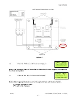
The EMS Signal point Installation Manual is a comprehensive user guide for our cutting-edge product. It provides step-by-step instructions on setting up and utilizing the EMS Signal point effectively. This manual is available for free download on our website, ensuring easy access and hassle-free installation for all users.
Share
Download

Reviews:
No comments
Related manuals for Signal point

SC-CH72
Brand: Panasonic Pages: 89

MAS22S
Brand: FARFISA INTERCOMS Pages: 4

CDV-43M
Brand: Commax Pages: 14

ZCX10
Brand: CAME Pages: 28

GH5T
Brand: Sumner Pages: 10

VIPA SLIO SDI
Brand: YASKAWA Pages: 135

DECOR CHIME CHM10157
Brand: SImx Pages: 6

MoveAround MA50
Brand: Safelift Pages: 20

SC600 Marcopolo
Brand: Valeo Pages: 12

V4R51
Brand: ZEBSBOARDS Pages: 9

Multicom CLASSIC 106-889
Brand: iCentral Pages: 37

PISO-P64 Series
Brand: ICP DAS USA Pages: 6

AV-04AFD
Brand: BAS-IP Pages: 8

9217967
Brand: Nedap Pages: 24

PR-2120
Brand: Hama Pages: 76

HVS-GPIO128
Brand: FOR-A Pages: 18

DECS125-15
Brand: Powerdist Pages: 7

KTP02
Brand: Dahua Pages: 32


