


Summary of Contents for BC-F20HWR2-200L
Page 2: ......
Page 29: ...26 l Mode settings Click on the main interface to switch modes select what you need ...
Page 32: ...29 ...
Page 33: ...30 ...
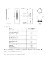
The Enertik BC-F20HWR2-200L is a high-performance air conditioning unit designed for residential spaces. Ensure a hassle-free installation with our comprehensive Installation Instructions Manual. Download the manual for free at 88.208.23.73:8080, where you'll find user-friendly instructions to help you set up and optimize your new Enertik AC unit.
Page 2: ......
Page 29: ...26 l Mode settings Click on the main interface to switch modes select what you need ...
Page 32: ...29 ...
Page 33: ...30 ...


