background image


www.enfora.com 


Spider® AT


User's Guide


GSM5108UG001 


Revision: Draft 


1/23/2009 


Summary of Contents for Spider AT

Page 1: ...www enfora com Spider AT User s Guide GSM5108UG001 Revision Draft 1 23 2009 ...

Page 2: ...als The user shall have only a revocable and limited license to use such New Materials in connection with the products for which they are intended Distribution or modification of any New Materials without Enfora s consent is strictly prohibited IN NO EVENT WILL ENFORA BE RESPONSIBLE FOR ANY INCIDENTAL INDIRECT CONSEQUENTIAL OR SPECIAL DAMAGES AS A RESULT OF THE USE OF ANY NEW MATERIALS ENFORA S MA...

Page 3: ... between Enfora and such other party HARDWARE During the warranty period applicable to the product hardware Enfora at its expense and in its sole discretion will repair or replace the product if it is determined to have a covered hardware defect provided that the purchaser first notifies Enfora of any such defect furnishes Enfora with a proof of purchase requests and obtains a return merchandize a...

Page 4: ... defect that is i discovered by purchaser during the warranty period but purchaser does not notify or request an RMA number from Enfora as required above until after the end of the warranty period ii caused by any accident misuse abuse improper installation handling or testing or unauthorized repair or modification of the product iii caused by use of any software other than any software supplied b...

Page 5: ...ic legal rights and the purchaser may have other legal rights that vary from jurisdiction to jurisdiction In some instances certain aspects of the product warranty may also be covered in a separate written agreement between Enfora and the distributor or reseller if any from whom purchaser purchased the product That agreement may provide for example a different product return procedure that may als...

Page 6: ...eryday use within 20cm of the body However the Spider AT is designed and manufactured not to exceed the emissions limits for exposure to radio frequency RF energy set by the Federal Communications Commission FCC of the U S Government These limits are part of comprehensive guidelines and establish permitted levels of RF energy for the general population These guidelines are based on the safety stan...

Page 7: ...Enfora strongly recommends that all installations hookups transmissions etc be performed by persons who are experienced in the fields of radio frequency technologies Enfora acknowledges that the installation setup and transmission guidelines contained within this publication are guidelines and that each installation may have variables outside of the guidelines contained herein Said variables must ...

Page 8: ...ts 10 2 Physical Description 11 2 1 Overview 11 2 2 Controls and Indicators 12 2 3 Dimensions 13 2 4 Environmental Specifications 14 2 4 1 Temperature 14 2 4 2 Water Resistance 14 2 5 Radio Performance Specifications 14 2 6 GSM GPRS Compliance Specifications 14 2 7 Battery Specifications 15 3 Initial Setup 16 3 1 Verify the Com Port 17 3 2 Configure the Device 19 3 2 1 Configure the Spider Asset T...

Page 9: ... 31 Install the USB Drivers 31 Appendix B SIM Card Installation 48 SIM Card Holder 48 SIM Card Installation 48 Appendix C Terminal Configuration 49 Set up HyperTerminal to Configure the Module 49 Test the HyperTerminal Setup 52 TABLE OF FIGURES Figure 1 Spider Asset Tag Circuit Board and Battery Pack 11 Figure 2 Top View of Spider Asset Tag 11 Figure 3 Bottom View of Spider Asset Tag 12 Figure 4 S...

Page 10: ...rdware Wizard Search for best driver 39 Figure 19 Hardware Wizard Windows Logo testing 40 Figure 20 Hardware Wizard Installation Progress 41 Figure 21 Hardware Wizard Installation Complete 42 Figure 22 Hardware Wizard New Hardware 43 Figure 23 Hardware Wizard Install from List 44 Figure 24 Hardware Wizard Search for best driver 45 Figure 25 Hardware Wizard Windows Logo testing 46 Figure 26 Hardwar...

Page 11: ...ensitivity Geofencing Simplified Over the Air Configuration Provisioning The Spider AT is based on Enfora s innovative Enabler III Low Power Platform with a built in programmable software environment Designed for the intelligent monitoring of non powered mobile and fixed assets the Spider AT is easily installed and managed The Spider AT can be provisioned through the Enfora Services Gateway and co...

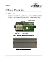
Page 12: ... quad band integrated platform Inside the black plastic case is a Enfora Enabler LPP0108 modem USB connector SIM holder and battery connector for the attached battery The figures below show an opened Spider AT Figure 1 Spider Asset Tag Circuit Board and Battery Pack Figure 2 Top View of Spider Asset Tag ...

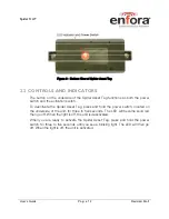
Page 13: ...ch To deactivate the Spider Asset Tag press and hold the power switch located on the underside of the unit for three to five seconds The LED will become solid red then go off When the light is off the unit is deactivated When you are ready to activate the Spider Asset Tag press and hold the power switch for three to five seconds until you see a blinking light The LED will then go off When the ligh...

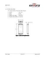
Page 14: ...a g e 13 Revision Draft 2 3 DIMENSIONS The measurements of the Spider Asset Tag are Length 146 7 mm Width 63 mm Height 20 4 mm Weight with battery 168 grams Weight without battery 110 grams Figure 4 Spider Asset Tag Dimensions ...

Page 15: ... that the device is protected against dust and low pressure jets of water This device cannot be immersed in water 2 5 RADIO PERFORMANCE SPECIFICATIONS Frequency 850 900 1800 1900 MHz Sensitivity 108 dBm typical Transmit Power Class 4 2W 850 900 MHz Class 1 1W 1800 1900 MHz 2 6 GSM GPRS COMPLIANCE SPECIFICATIONS The following list shows the certifications for the Spider Asset Tag FCC Parts 15 22 24...

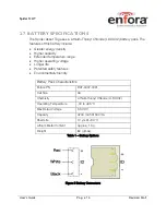
Page 16: ...tended temperature range Higher operating voltage Longer life Patented safety features Environmentally friendly Battery Pack Characteristics Enfora PN BAT 0007 0001 Cell Size AA Chemistry Lithium thionyl Chloride LI SOCl2 Operating Temperature 40 to 85 C Max Rated Voltage 3 9 VDC Capacity 4200 mAh 500 mA Shelf Life 10 yrs 30 C Lithium Metal Content Approx 1 3 g Weight 80 g max Table 1 Battery Opti...

Page 17: ...n the screws and separate the two halves of the unit 4 Make sure the battery is connected refer to Connecting the battery in section 5 1 2 Figure 6 Internal View of Spider Asset Tag with Circuit Board and Battery Pack 5 Remove the battery pack from the half of the Spider Asset Tag that contains the circuit board You don t need to disconnect the battery connector just move the battery pack out of t...

Page 18: ...now activated and will begin transmitting data Note Verify the Server is receiving messages from the device Note If you are ready to deploy the Spider Asset Tag mount the unit on the asset you need to locate refer to Section 4 If you are not ready to deploy deactivate the unit until you are ready refer to Section 2 2 3 1 VERIFY THE COM PORT In order to send commands to the Spider Asset Tag you wil...

Page 19: ...r s Guide P a g e 18 Revision Draft Figure 7 Device Manager Window In this case the Enfora Enabler IIIG LPP Modem has been assigned to COM9 You can now use a terminal program to send commands to the Spider Asset Tag ...

Page 20: ... Provisioner to configure the device over the air basic communication parameters must be configured using a terminal program and USB connection 3 2 1 CONFIGURE THE SPIDER ASSET TAG MANUALLY USING A TERMINAL EMULATOR Any terminal emulator program such as ProComm or HyperTerminal can be used to send AT commands to the device Configure the terminal emulator with the following settings Baud rate is fi...

Page 21: ...is User s Guide Below are the basic commands required to establish communication between a device and the Gateway Provisioner server AT Command Command Description AT MDMID MDMID Choose a unique identifier for your modem ID AT CGDCONT 1 IP APN Configure Carrier APN where APN APN specific to the SIM used AT UDPAPI PORT Configure Server Port where PORT Port that the Gateway server is monitoring for ...

Page 22: ...ng to the server the device will be in sleep mode and will not receive commands from the Provisioner server until it wakes up for its daily report Note If you require the device to maintain contact with the Provisioner server for testing include the following commands AT WAKEUP 1 1 AT W This will result in the device reporting to the server once per minute This configuration will drain the battery...

Page 23: ... procedure describes the mounting of the Spider AT Please read this entire procedure and ensure that all equipment is available and personnel are trained before starting the work 4 1 HARDWARE NEEDED TO MOUNT DEVICE The following is a list of mounting hardware that may be used with the Spider AT Appropriate Mounting Screws Qty 4 Screws shown in Figure 8 Spider AT and Mounting Hardware are 8 Self Dr...

Page 24: ...ng surface must not allow water to pool around the device Care should be taken to avoid damaging wiring electronics plumbing etc when drilling holes to mount the device The device should be mounted where it is protected from being impacted during operation The supported material of the mounting location includes but is not limited to Metal Plastic Wood 4 3 PRE DRILLING OF MOUNTING HOLES After sele...

Page 25: ... with the remaining three Screws Figure 10 Spider AT and Mounting Hardware Insure the Device is turned on Flashing light indicates that the Device is turned on Align the Device with the pre drilled screw holes Insert one of the screws assembled above through one of the screw holes in the Device Partially tighten the Screw into the mounting surface Repeat this process until all four screws are star...

Page 26: ...also be mounted using Wire Tie Wraps The screw holes are sized so the Tie Wraps can be inserted through them as shown in Figure 11 Mounting Cable Ties Figure 11 Mounting Cable Ties Warning Take care not to fasten Tie Wraps over sharp edges as this may cause excesive wear causing the Tie Wraps to break ...

Page 27: ...NECT THE BATTERY 1 Remove the Spider Asset Tag from its mounted location 2 Fully loosen the two screws so the two halves of the unit are separated Figure 12 Open Unit 3 Disconnect the old battery by grasping the battery cable close to the connector and gently pull upwards as shown in Figure 13 Remove Battery Figure 13 Remove Battery 4 Remove the battery from the case ...

Page 28: ... Insert New Battery Figure 14 Insert New Battery 2 Connect the new battery by attaching the connector to the battery terminals 3 The correct orientation of the battery cable prior to insertion into the PCB mounted battery connector is with the red wire positioned closest to the wall of the plastic housing Shown in Figure 15 Battery Cable Orientation Figure 15 Battery Cable Orientation ...

Page 29: ...the connector jack and apply pressure straight down on to the battery cable connector until the connectors are fully engaged Shown in Figure 16 Connect the cable Figure 16 Connect the cable 5 Close the Spider Asset Tag and replace the screws 6 Remount the device in its original location ...

Page 30: ...ld deactivate the Asset Tag so as not to drain the battery To deactivate the Spider Asset Tag press and hold the power switch located on the underside of the unit for three to five seconds The LED will become solid red then go off When the light is off the unit is deactivated Figure 17 LED Indicator and Power Switch When you are ready to activate the Spider Asset Tag press and hold the power switc...

Page 31: ...nfiguration is approximately 1 year Other configuration factors that will affect the battery life include but are not limited to Report Frequency Device Temperature Length of awake time Atmospheric conditions The following graph shows estimated battery life for a typical configuration reporting 1 to 7 times per week This estimate is based on a device operating at room temperature Figure 18 Battery...

Page 32: ...T TAG TO A USB PORT Supported Operating Systems include Windows 2000 Windows XP and Windows Vista When you connect the Spider Asset Tag to the computer you will be prompted to install the drivers Note In order to access the USB port on the Spider Asset Tag you will need to remove the cover The USB connector is located on the circuit board inside the unit Follow the steps in the next section to ins...

Page 33: ...ete the process will automatically begin again The second step will install the Enabler III G LPP Trace The third step will install the Enabler IIIG LPP Modem 1 The Windows Operating System will detect the new USB device 2 You will see the following screen Figure 19 Found New Hardware Wizard Window 3 Click on No not this time 4 Click Next 5 You will see the following screen ...

Page 34: ...uide P a g e 33 Revision Draft Figure 20 Hardware Wizard Install from specific location 6 Click the radio button next to Install from a list or specific location Advanced 7 Click Next 8 You will see the following screen ...

Page 35: ...Hardware Wizard Search for best driver 9 Click on the check box marked Include this location in the search 10 Browse to the location on your computer where the USB drivers are located 11 Click Next 12 You will see the screen that shows the installation progress ...

Page 36: ...Spider AT User s Guide P a g e 35 Revision Draft Figure 22 Hardware Wizard Install Progress 13 When the installation of the Locosto USB device is complete you will see the following screen ...

Page 37: ...er s Guide P a g e 36 Revision Draft Figure 23 Hardware Wizard Completing 14 Click Finish When this installation is complete the installation process for the USB device will begin You will see the following screen ...

Page 38: ...Spider AT User s Guide P a g e 37 Revision Draft Figure 24 Hardware Wizard Install from specific location 15 Click on No not this time 16 Click Next 17 You will see the following screen ...

Page 39: ...r s Guide P a g e 38 Revision Draft Figure 25 Hardware Wizard Install from List 18 Click the radio button next to Install from a list or specific location Advanced 19 Click Next 20 You will see the following screen ...

Page 40: ...ft Figure 26 Hardware Wizard Search for best driver 21 Click on the check box marked Include this location in the search 22 Browse to the location on your computer where the USB drivers are located 23 Click Next 24 You may see the following screen ...

Page 41: ... AT User s Guide P a g e 40 Revision Draft Figure 27 Hardware Wizard Windows Logo testing Note If you see this warning click on Continue Anyway 25 You will see the screen that shows the installation progress ...

Page 42: ...pider AT User s Guide P a g e 41 Revision Draft Figure 28 Hardware Wizard Installation Progress 26 When the installation of the Enfora Enabler IIIG LPP Trace is complete you will see the following screen ...

Page 43: ...Guide P a g e 42 Revision Draft Figure 29 Hardware Wizard Installation Complete 27 Click Finish When this installation is complete the installation process for the USB device will begin You will see the following screen ...

Page 44: ...Spider AT User s Guide P a g e 43 Revision Draft Figure 30 Hardware Wizard New Hardware 28 Click on No not this time 29 Click Next 30 You will see the following screen ...

Page 45: ...r s Guide P a g e 44 Revision Draft Figure 31 Hardware Wizard Install from List 31 Click the radio button next to Install from a list or specific location Advanced 32 Click Next 33 You will see the following screen ...

Page 46: ...ft Figure 32 Hardware Wizard Search for best driver 34 Click on the check box marked Include this location in the search 35 Browse to the location on your computer where the USB drivers are located 36 Click Next 37 You may see the following screen ...

Page 47: ...Spider AT User s Guide P a g e 46 Revision Draft Figure 33 Hardware Wizard Windows Logo testing Note If you see this warning click on Continue Anyway ...

Page 48: ...Spider AT User s Guide P a g e 47 Revision Draft Figure 34 Hardware Wizard Installation Complete 38 Click Finish to complete the installation of the Enfora Enabler IIIG LPP Modem drivers ...

Page 49: ...cure connection Figure 35 Spider Asset Tag SIM Holder SIM CARD INSTALLATION 1 Slide the SIM card into the open SIM holder 2 Make sure the SIM card notch is lined up properly see Figure 35 3 Close the holder and slide it until it is completely closed Note The SIM card is not provided with the Spider Asset Tag device The SIM must be obtained from the GSM GPRS service provider and must be provisioned...

Page 50: ...onfigure the modem However any standard terminal emulator program can be used SET UP HYPERTERMINAL TO CONFIGURE THE MODULE These instructions illustrate how to correctly configure HyperTerminal in Windows XP Setup HyperTerminal 1 On Windows XP click on Start Programs Accessories Communications HyperTerminal The Connection Description window appears Figure 36 Figure 36 Connection Description Window...

Page 51: ... AT User s Guide P a g e 50 Revision Draft Figure 37 Connect To Window 4 Change the Connect Using setting to the Com port that was determined in Step 2 5 Click OK The Port Properties window appears Figure 38 ...

Page 52: ...Spider AT User s Guide P a g e 51 Revision Draft Figure 38 Port Properties Window 6 Make sure the settings match the example 7 Click OK The HyperTerminal Program Window appears Figure 39 ...

Page 53: ...e main window 2 Type AT and press Enter 3 The modem should respond back with 0 or OK in the Main Window 4 If this happens the COM port is configured correctly If not go back and check your settings 5 At this point you are ready to start configuring your device with AT commands Section 3 2 of this guide provides details about configuring your device ...

Reviews: