background image


EN-898X USER MANUAL 

1. Introduction…………………………………………….2 

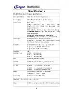
2. Specification………………..…………………………..6 

3. Setup 

3-1. Installing the server board………………………….

7


3-2. Adding components to the server board……12 

3-3. Reattaching the cover…………………………..12 

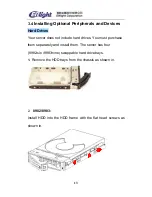
3-4. Installing optional peripherals and devices 

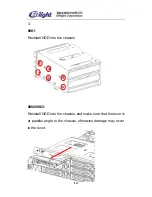
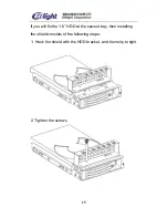
Hard Drives………………………………………….

13


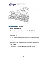
CD-ROM/FDD………………………………………..

16


Power Supply………………………………………..

17


Fan……………………………………………………..

18


PCI Slot……………………………………………………

22


3-5. Installing 2U in the cabinet……………………..25 

4. About the Back Plane………………………………...25 

5. Connecting the control plane……………………….29 

6. About the LED panel and front panel………………30 

7. About Screws…………………………………………..32 

9. About SAF-TE…………………………………………..33 

10.SCSI MANAGER……………………………………….34 

11. Addenda (

898X series compare)………………………45


Summary of Contents for EN-898X

Page 1: ...hing the cover 12 3 4 Installing optional peripherals and devices Hard Drives 13 CD ROM FDD 16 Power Supply 17 Fan 18 PCI Slot 22 3 5 Installing 2U in the cabinet 25 4 About the Back Plane 25 5 Connec...

Page 2: ...h hard disk in tray and slim CD ROM and standard floppy disk drive bay 5 25 drive bay you can stack the 2U units inastandard19 rackcabinet Witha300W 8982 8983 460 W for single and redundant power supp...

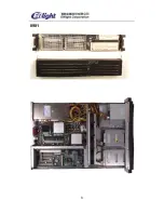
Page 3: ...3 8981...

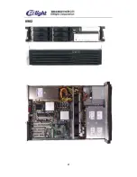
Page 4: ...4 8982...

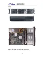
Page 5: ...5 8983 notice this pictures are just for reference...

Page 6: ...82 8983 4 x internal 80 x 80 x 38mm Easy swap cooling fans 3 x rear 40 x40 x 20mm cooling fans Back Plane 8982 1 2 8983 SCSI Back plane support Ultra 320 Support up to 15 000 RPM SCSI hard disk Suppor...

Page 7: ...teps 1 Removing the cover 2 Removing the riser card Fan pole 3 Mounting the server board in the chassis 4 Cabling the server board to the other chassis components 5 Adding processors and memory to the...

Page 8: ...lable To mount the server board 1 Fix the motherboard s screws And save the screws 2 Fix the I O shields To position the shield correctly the outline of the connectors on the I O shield should be view...

Page 9: ...supplied with the chassis through the holes on the server board CPU Bracket To remove the CPU bracket Nip the hook of the bracket and pull the bracket and then the bracket is divorced from the hole of...

Page 10: ...10 Notice The white screw is used to support the motherboard M B Insulation PAD The M B Insulation PAD above the pedestal will be used without the CPU bracket...

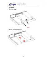
Page 11: ...11 as follows aim at the holes holes Affix the tape to the pedestal...

Page 12: ...r installing the server board you must add the desired number of processor sand memory cards 3 3 Reattaching the Cover Once the server board and its components are installed you are assembling the sys...

Page 13: ...oes not include hard drives You must purchase them separately and install them The server has four 8982 six 8983 nine swappable hard drive bays 1 Remove the HDD trays from the chassis as shown in 2 89...

Page 14: ...14 3 8981 Reinstall HDD into the chassis 8982 8983 Reinstall HDD into the chassis and make sure that the lever is at parallel angle to the chassis otherwise damage may occur to the lever...

Page 15: ...15 If you will fix the 1 6 HDD at the second tray then installing the shield consists of the following steps 1 Hook the shield with the HDD bracket and then slip to right 2 Tighten the screws...

Page 16: ...o fix the CD ROM shield 2 Remove the CD ROM shield from the chassis the slide is at the OPEN 3 Fix the CD ROM bracket to the pedestal using the mounting screws 4 Slip the CD ROM drive to the CD ROM br...

Page 17: ...x82 2mm W D H To fix power supply 1 Slide the power supply into the chassis and make sure it is seated in the chassis connector 2 Connect the power cord to the power cord receptacle and plug the cord...

Page 18: ...ert the fan assembly into the chassis 2 Plug the fan cables back into the connectors on the power Back plane cooling fans 8982 8983 1 Insert the fan assembly into the chassis 2 Plug the fan cables bac...

Page 19: ...Installing the Cooling fans consists of the following steps 1 Fix the I O shields 2 Nip the left hook to the pedestal 3 Fix the right button to the pedestal 4 Fix the three fans into the back of the...

Page 20: ...20 as follows L1 R1 the left fan L2 R2 the second fan L3 R3 the right fan...

Page 21: ...21 Notes If installing the Enlight s I O shield make sure that the three hooks is at 80 angle to the chassis then fix the three fans...

Page 22: ...an add three PCI cards to this server Installing PCI SCSI add in card Insert the riser card to the PCI slot Insert the daughter board to the PCI slot And the PCI slot of daughter board MUST same with...

Page 23: ...23 898X D01 You can add Low profile PCI cards to this server...

Page 24: ...24 898X E01 You can add two PCI cards to this server...

Page 25: ...abinet 5 About the Back Plane 8982 8983 6HDD Front panel Connector 8983 9 HDD divided into two SCSI channels 1 back plane 6 HDD 1 back plane 3 HDD 6HDD Back Plane The back plane allows you to control...

Page 26: ...eight device slots Table 3 13 describes the states that are displayed Table 3 13 Visual Indicator State Device Status Indicator Light No Error Faulty or rebuild stopped Rebuild Identify Off Steady on...

Page 27: ...or lights 3HDD Back Plane 1 SCSI Connector Connect SCSI cable 2 Front panel Connector Connector for LED board with cable 3 Switch there is one button at the back plane This is function of noise elimin...

Page 28: ...l be blinking Power Both red and green LED will be blinking Visual Indicators The GEM318 controls status indicator lights for up to eight device slots Table 3 13 describes the states that are displaye...

Page 29: ...dentify LED indicates which slot is housing the faulty device and shows the user in which slot a replacement drive should be installed Note Issuing a SCSI reset message or SCSI bus device reset messag...

Page 30: ...green Fan Fail LED When the Fan error or not active the LED will be show in and annunciator will start HDD Activity LED When the hard disk access the LED will be show in green Volt Alarm LED When the...

Page 31: ...ll be show in and annunciator will start NIC Activity LED When the NIC is run the LED will be access green System Fail LED When the system is abnormity the LED will be show in 2 Front panel Power Swit...

Page 32: ...mory dump can be performed to determine the cause of the problem ACPI Switch Advanced power management 8 About Screws A Four of them are to fix the power Two of them are to fix the shield B Two of the...

Page 33: ...82 supports part of SAT TE commands The objective of the SAF TE Interface is to provide a standard non proprietary way for third party disk and RAID controllers to be automatically integrated with per...

Page 34: ...e first time the SCSI Manager is being used it will require a serial number to be entered then it will ask the user to set his own password Fig 13 Thereafter it will require the user to enter the pass...

Page 35: ...ghtcorp Click on the Operation menu a drop down menu will be displayed Modify Password Modify user password Expert mode Enter professional display setting the default setting is Common user mode Under...

Page 36: ...n Server Address Program Updating Server Address Auto Update Auto updating Operation Guide Using the examples of operations under the Common user mode some information displaying on the screen will be...

Page 37: ...sk Tagged Queuing Adapter Scans Down Adapter Used PIO When clicked on the specific settings under every controlling card the right panel will display Vendor ID Product ID Firmware Revision Level SCSI...

Page 38: ...of Device Slots Door Lock Installed Number of Temperature Sensor Audible Alarm Installed Celsius When click on the Enclosure Status the right panel will display some information Device Slot n SCSI ID...

Page 39: ...ower Failure Status Drive Failure Status Drive Warning Status When under the Expert mode users can see all the information returned from the hard drive click on the settings under one of the control c...

Page 40: ...Slot Operation 7 Send Global Flags When double click one of them the dialog box will display This dialog box is for users who are very familiar with the SAF TE rules when performing the write command...

Page 41: ...ram Updating While the program is running it will detect if there is the updated version can be used at any moment If so the program will be updated automatically The program will be updated automatic...

Page 42: ...management is needed If the AutoUpdate is no need just disable the AutoUpdate item Detect program updating version manually Show as the following menu When clicks the Check Version item the program wi...

Page 43: ...in the 8721 8982 or 8983 device and those devices could be automatically installed 2 If the machine is installed the device of 8721 8982 or 8983 and then setup this compress package the device manage...

Page 44: ...44 4 We can update the software if we need to set up new equipment...

Page 45: ...1E01 4IDE HDD 2PCI same as 8981C01 4 80 80 25 mm 8982C01 3PCI Provide64bits PCI Riser card option 32bits PCI Riser card 8982D01 Low profile 8982E01 6Hot Sw ap SCSI HDD 1slimCD ROM 1standard FDD 1 5 25...

Reviews: