background image

Single Wallbox

Installation manual

SWB_4xx_22_T2
SWB_4xx_22_C7
SWB_4xx_22_T2S
SWB_4xx_22_T2SE

English

Summary of Contents for Single Wallbox

Page 1: ...Single Wallbox Installation manual SWB_4xx_22_T2 SWB_4xx_22_C7 SWB_4xx_22_T2S SWB_4xx_22_T2SE English ...

Page 2: ...tallation Manual please scan the QR code or use the link https www enovates com manual pedestal installation To access the Single Wallbox User Manual please scan the QR code or use the link https www enovates com manual user manual To access the Single Wallbox Acessories Manual please scan the QR code or use the link https www enovates com manual accessoire manuals ...

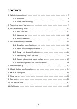
Page 3: ...ols 13 4 Installation requirements 14 4 1 Installer specifications 14 4 2 General cable specifications 14 4 3 Power cord specifications 14 4 4 Grounding specifications 15 4 5 Required nominal input voltage 15 4 6 Electrical protection specifications 16 5 Wall mounting 17 6 Check before configuration 24 7 How to configure 25 8 Final note 26 9 Support 26 10 Abbreviations 27 11 Software 29 3 ...

Page 4: ......

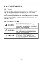
Page 5: ...ad the safety instructions in this document before installing and using the product 1 2 Safety terminology Danger texts provide important information to avoid situations with a high chance to cause severe malfunction damage injuries or death Warning texts provide important information to avoid situations with a significant chance to cause malfunction damage injuries or death Caution texts provide ...

Page 6: ...ctrical supply Do not use the product if one or more of its components may have become damaged or compromised Always make sure the product is not submerged in water and is not located near water Do not handle the product with wet hands and make sure no liquid is sprayed on it or comes into contact with it Store the charging cable in the socket to prevent unnecessary exposure to contamination or mo...

Page 7: ...h temperatures may impair functionality cause damage or cause hazards Damage to the product may cause injury or death Respect the product s operating parameters and technical specifications and make sure damage is not inflicted or allowed to accumulate on the product Do not use the product if it fails to operate normally or appears cracked frayed broken or otherwise damaged If you suspect the prod...

Page 8: ... magnetic devices away from the product as their use in the vicinity of the product may negatively affect the product s functionality even to the point of causing damage to the product Use the product only in temperatures within its operating range of 30 C to 50 C Only transport and store the product in its original packaging Do not subject the product to strong force impact pull twist tangle or d...

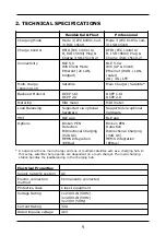
Page 9: ...ter Load Balancing Supported via optional hardware Supported via optional hardware HMI BLE app BLE app Options Broken PEN Detection BiDirectional Charging V2G AC HEMS Integration EEBus Broken PEN Detection BiDirectional Charging V2G AC HEMS Integration EEBus A network with one main charger and one or multiple satellites acts as a charging hub In this setup satellite charge points are dependent on ...

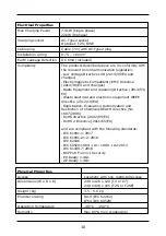
Page 10: ...2014 53 EU Waste electrical and electronic equipment WEEE directive 2012 19 EU Registration Evaluation Authorization and Restriction of Chemicals REACH directive No 1907 2006 RoHS directive 2002 95 EC RoHS 2 Directive 2011 65 EU and are compliant with the following standards IEC 61851 1 2017 IEC 61851 21 2 2018 IEC 62196 IEC 60529 1989 A1 1999 A2 2013 IEC 61439 7 2018 OCPP1 6 Full incl Security EV...

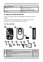
Page 11: ...e necessary tools for installation are delivered with the product Before you start please check that all tools and components required for an easy installation are available 3 1 Box content 1 2 3 4 5 6 7 8 9 11 10 12 Description Amount 1 Charger unit T2 version or C7 version with fixed cable x1 2 Cover contains socket lid x1 Cable block x1 3 Cable bridge x1 11 ...

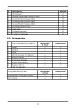
Page 12: ...lation Manual x1 12 C sticker hexagonal x1 3 2 Accessories Can be additionally purchased Residential Fleet Professional 1 eDSBI x x 2 eDSBIII x x 3 eDLB x 4 eDP1B Dynamic P1 Balancer x x 5 External Coil set x x 6 Single Side Pedestal x x 7 Double Side Pedestal x x 8 Pedestal Anchor flat for solid soil x x Compatible external tools Residential Fleet Professional Potential free on off peak contact x...

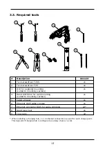
Page 13: ...ace x1 4 Hand drill 8mm for wall mounting suited to mounting surface x1 5 Cable stripper x1 6 Ethernet RJ45 cable crimper x1 7 Ethernet connector RJ45 for cable crimping x2 8 Spirit level tool x1 9 Tie wraps x2 When installing a charging hub 1 or 2 ethernet connectors are used for each charge point This depends if charging hub is configured as a daisy chain or a star 13 ...

Page 14: ...the charge point with the internet Wifi and 4G only professional are also possible to connect the charge point with the internet The ethernet cable is not to be used underground unless through a holding tube or reinforced STP cable in order to prevent corrosion by moisture or rupture by ground shifts Insofar as is possible the cables should already be present and ready to connect to the product at...

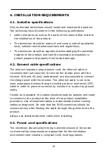
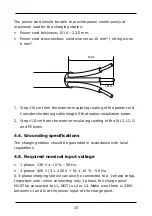
Page 15: ...n easier 2 Strip 1 8 cm from the exterior insulating coating of the N L3 L2 L1 and PE wires 4 4 Grounding specifications The charging station should be grounded in accordance with local regulations 4 5 Required nominal input voltage 1 phase 230 V 10 50 Hz 3 phase 400 V 3 400 V N 10 50 Hz A 3 phase charging station can also be connected to a 1 phase setup Important note when connecting only 1 phase...

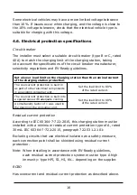
Page 16: ...of other electrical components in an existing consumer unit Set the load limit to 80 of the rated current The overcurrent protection is built into a special case with adequate cooling A simultaneity factor of 1 was used in the design of the consumer unit Set the load limit to 90 of the rated current Residual current protection According to IEC 60364 7 722 2015 this charging station must be install...

Page 17: ...al see the installation booklet which is accessible through the QR code or web link on the first page of this manual The wall mounting procedure consists of a few steps 1 Install the wall bracket 2 Secure the cable block to the wall bracket 3 Slide the charger onto the wall bracket 4 Secure the charger to the wall bracket 5 Connect the cables 6 Attach and secure the cover 7 Attach and secure the s...

Page 18: ...vides at least 30 centimeters of space around the charger when the charger is attached to it Lead the cables through the circular holes at the bottom of the bracket Use either the holes in the back support or the holes in the bottom support as is most convenient for your cable setup 2 If the mounting surface consists of concrete or brick fix the bracket securely to the wall using the provided 3 8m...

Page 19: ...ve the bridge component from the cable block Pull the cables through the circular holes and through the cable block 2 Use the provided 2 M5x16 Torque 1 2Nm screws to secure the cable block to the wall bracket Keep the bridge component nearby 1 2 1 cable from back wall 2 cable from below ground Slide the charger onto the wall bracket 1 Align the niche with the wall bracket 19 ...

Page 20: ... the wall bracket so that the wall bracket slots into the back of the charger unit Lead the cables into the charger unit through the hole at the bottom Secure the charger to the wall bracket Use the provided 2 M6x14 Torque 1 2Nm screws to secure the charger unit to the wall bracket through the clearance holes and tapped holes inside of the mounted charger 20 ...

Page 21: ... later Threephaseconfiguration Onephaseconfiguration 1 2 3 4 Threephaseconfiguration NoN cable 2 Connect each cable to its corresponding cable slot using the locking system lift the slot lid insert the cable and close the slot lid The charger unit contains labelled cable slots In order from left to right cables should be attached to the slots as follows N slot blue cable L3 slot grey cable L2 slot...

Page 22: ...the unstripped portion under the slot The unstripped cable portion should protrude from the bridge by 1 centimeter Professional edition only Install a SIM card in the SIM card slot at the top right of the charger unit 4 Lead the ethernet cable through the 3 cable grommet in the cable block and pinch the connector onto the cable 5 Connect the ethernet cable to the top ethernet slot marked ETH1 at t...

Page 23: ...les around the charger socket and at the bottom of the cover Note It is recommended to use copper grease when securing the cover with the screws Attach and secure the socket lid The socket lid is attached and secured using a bayonet locking system 1 Place the socket lid diagonally onto the charger socket frame and turn clockwise to slot the socket lid in place 2 Lift the socket lid to reveal a tap...

Page 24: ...charger is installed in a public place attach a C sticker adhering to the EN 17186 standard to the front of the lid in line with the hexagonal indentation on the lid 6 CHECK BEFORE CONFIGURATION Checks before switching on 1 Check that all screws and connections are attached firmly 2 Check that all phase cables have been connected correctly 24 ...

Page 25: ...nt protection may be caused by a grounding error leakage or faulty relay If after resetting the protections the product cannot be reactivated or the protections are tripped again contact the installer or relevant provider s You are now ready to configure the charger 7 HOW TO CONFIGURE The charger can be configured using the My eNovates app available in the App Store and Play Store The app is compa...

Page 26: ...s https play google com store apps details id com enovates myeNovates 8 FINAL NOTE The box contains an extra Installer and User QR sticker The User QR code should be kept by the user and should not be displayed publicly The Installer QR code should be pasted above the miniature circuit breaker MCB in the electrical control cabinet 9 SUPPORT If you require customer support please contact the instal...

Page 27: ...ers storages and logical managing consumers producers storages and logical managing EMC Electromagnetic Compatibility EN European Norm EU European Union EV Electric Vehicle HEMS Home Energy Management System HMI Human Machine Interface Hz Hertz IEC International Electrotechnical Commission IK Impact Protection rating IP Ingress Protection code ISO International Organization for Standardization kW ...

Page 28: ...ce RoHS Restriction of the use of certain Hazardous Substances in electrical and electronic Equipment SIM Subscriber Identity Module STP Shielded Twister Pair T2 Type 2 socket T2S Type 2 socket shutter T2SE Type 2 socket shutter schucko UTP Unshielded Twisted Pair V Volt V2G Vehicle To Grid WAN Wide Area Network WEEE Waste Electrical and Electronic Equipment Wifi Wireless Fidelity XVB Cable with i...

Page 29: ...BSD 2 Clause BSD 3 Clause BSD 4 Clause bzip2 CLOSED EPL 1 0 GFDL 1 2 GPL 2 0 GPL 2 GPL 3 0 with GCC exception GPLv2 GPLv2 GPLv3 GPLv3 ISC LGPL 2 1 LGPL 2 1 LGPLv2 LGPLv2 1 LGPLv2 1 LGPLv2 LGPLv3 LGPLv3 MICROCHIP_CRYPTOAUTHLIB_LICENSE MIT MIT style MPL 1 1 MPL 2 0 29 ...

Page 30: ...NTP openssl PD Proprietary PSFv2 Zlib 30 ...

Page 31: ...NOTES 31 ...

Page 32: ...Manufacturer eNovates N V Brandstraat 13 9160 Lokeren Belgium KBO 0833 289 547 Paste Installer App sticker here Paste User App sticker here EN I WL 2 00 0 ...

Reviews: