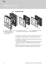
background image

Druck-Nr.:

2902 5037

Stand:

25/19

EN

Made in Germany

26

Operation Mode

15:37

09:12

InfraStyle / InfraStyle i

Control unit for infrared cabins

Operating Instructions

Summary of Contents for InfraStyle

Page 1: ...Druck Nr 2902 5037 Stand 25 19 EN Made in Germany 26 Operation Mode 15 37 09 12 InfraStyle InfraStyle i Control unit for infrared cabins Operating Instructions ...

Page 2: ... ted Compensation will be claimed in the event of infringements All rights reserved with regard to patent claims or submission of design or utility patent Characters symbols and illustrations Revision history EOS Saunatechnik GmbH Schneiderstriesch 1 35759 Driedorf Germany Tel 49 2775 82 0 Fax 49 2775 82 431 Web www eos sauna com Additional information about an operating step Cross reference to a ...

Page 3: ...he system on off 19 4 2 Switching the lighting on off 20 4 3 Configuration upon commissioning or after a reset 21 4 4 Adjusting the IR emitters 24 4 5 Basic settings 25 4 5 1 IR operating mode 27 4 5 2 IR temperature 28 4 5 3 IR intensity 29 4 5 4 Automatic start time 30 4 5 5 Dimming the cabin lighting 32 4 5 6 One time heating period 34 4 5 7 Recurring heating periods 36 4 5 8 Switching ECO mode...

Page 4: ...intenance 63 5 1 3 Switching hysteresis for the IR temperature 64 5 1 4 Reset function 65 5 1 5 Temperature control 66 5 1 6 Configuring the channel groups 68 5 1 7 Setting the ECO runtime 71 5 2 Defining the light source manually 72 5 3 Heating period limiter 75 5 4 Updating firmware 76 6 General terms and conditions of service 80 7 Disposal 83 ...

Page 5: ...withthe following terms and symbols DANGER Danger Indicates a hazardous situation which if not avoided will result in death WARNING Warning Indicates a hazardous situation which if not avoided could result in death or serious injury CAUTION Caution Indicates a hazardous situation which if not avoided could result in minor or moderate injury NOTICE Notice Indicates a hazardous situation which if no...

Page 6: ...0 part 701 The system must be disconnected and removed entirely from the mains supply before commencing installation and repair work The housing cover must only be removed by a specialist Do not install the control panel relay boxes or modules in en closed cabinets or wood panelling Fire hazard from overheating Infrared emitters and heating foils without overheat protection can lead to overheating...

Page 7: ... shock A risk to life and limb from electric shock and fire arises in the event of improper repair work This risk also applies after work is com pleted The housing cover must only be removed by a specialist Repairs and installations must only be performed by a trained specialist The system must be disconnected and removed entirely from the mains supply before commencing repair work Use only origin...

Page 8: ...re each use Operation by children or persons with reduced mental capacity Children and persons with reduced mental capacity can be a risk Children must be supervised to ensure they do not play with the unit Children under 8 should not operate the infrared cabin The settings for the heating period must only be used by chil dren under 8 years of age if they are supervised by an adult The infrared ca...

Page 9: ...ld and similar electrical appliances safety Part 2 30 Particular require ments for room heaters DIN EN 60335 2 53 Household and similar electrical appliances safety Part 2 53 Particular require ments for sauna heating appliances and infrared cabins DIN EN 60335 2 96 Household and similar electrical appliances safety Part 2 96 Particular require ments for heating equipment DIN EN 55014 1 Electromag...

Page 10: ... EmoStyle i for mounting in the cabin in black maple or black walnut and in white maple or white walnut Software version R 3 50 or higher must be installed in the control panel Update your software if it does not match the specifications above See 4 6 5 Operating data 51 5 4 Updating firmware 76 2 1 Control panels Nameplate The nameplate is located on the inside of the front panel next to the circ...

Page 11: ...eased risk of mechanical damage InfraStyle InfraStyle i control panels The InfraStyle InfraStyle i control panels are suitable for private and com mercial use to control infrared cabins They must only be mounted on a wall Foreseeable misuse The following are considered instances of foreseeable misuse The infrared heating foils do not have an integrated temperature sensor with overheat protection T...

Page 12: ...ntrol panel InfraStyle for mounting outside of the cabin either in or on the wall InfraStyle i for mounting inside the cabin in the wall A InfraStyle control panel with housing for mounting in the wall B InfraStyle i control panel with housing for mounting in the wall C Voltage regulator for InfraStyle i control panel D Removal tool for front panel E Installation and operating Instructions F Contr...

Page 13: ... 5861 25 m connecting cable for sauna bus RJ12 RJ12 94 4647 50 m connecting cable for sauna bus RJ12 RJ12 94 4648 IR module as installation add on 94 6966 IR plug in module with adapter cable 94 2046 IR plug in module without adapter cable 94 4960 2 5 m connecting cable for IR plug in module 94 4396 Set SBM ECO push button 94 6980 SBM WCI 01 web app module 94 5987 SBM remote start 94 5782 SBM FL75...

Page 14: ...o options are available Model for mounting in the wall A The housing is mounted in the wall Model for mounting on the wall F The housing is mounted on the wall The connecting cable for the relay box is fed through the back of the hous ing of all control panels The circuit board is affixed to the front panel A Housing for mounting in the wall B Front panel with display C Icons for program selection...

Page 15: ...uit board connections InfraStyle i InfraStyle i circuit board connections A Front panel back B Sauna bus connection C Circuit board diagram D Memory card microSD connection A Front panel back B Insulation C Circuit board diagram D Sauna bus connection E Voltage regulator connection F Memory card microSD connection B D A C B F A E D C ...

Page 16: ...Connection for lighting Min 5 W 20 mA resistive load max 100 W Dimmable energy saving bulbs max 35 W Light source with conventional transformers max 60 VA Use only dimmable light sources Sensor system Digital sensor for ambient temperature Heating period limiter Up to 6 hrs 12 hrs infinite Ambient temperature InfraStyle 10 C to 40 C InfraStyle i 10 C to 110 C Storage temperature 20 C to 60 C Housi...

Page 17: ...nel All functions must be configured to commission the system Add on modules or accessories are detected after the unit is switched on again and their corresponding icons appear in the sub menus Control panels A Front panel B Display C Status bar D Function buttons 09 12 D B 09 12 B D InfraStyle InfraStyle i A A C C ...

Page 18: ...irmed values are displayed in green Example Entering values The home screen standby appears after the display has not been touched for 15 seconds Settings that have not been saved are lost Date and time are saved if the built in battery is in working order All other settings are saved permanently Tap the icon buttons to select and confirm functions Scroll back through functions On off Close sub me...

Page 19: ... approx 3 seconds until the cabin is switched on The cabin is switched on with the pre set parameters after the countdown Switching the system off 1 Press Position I Relay box is switched on The relay box is ready for operation in standby mode Position 0 Relay box is completely switched off Parts of the circuit board are still energised Position II Cabin lighting is switched on relay box is switch...

Page 20: ...stive loads max 100 W Dimmable energy saving bulbs max 35 W Light sources with conventional transformers max 60 VA Dimmable LED bulbs max 60 W Lighting can be mounted anywhere however not in the emitting range of an IR emitter NOTICE Material damage Lighting and the control panel could become damaged if non dimmable light sources are installed In this case the warranty be comes void Do not install...

Page 21: ...ff 1 Press 4 3 Configuration upon commissioning or after a reset The settings must be redefined upon commissioning and after a complete system reset The program guides you through the required steps Defining the user interface language 1 Select a language and confirm 09 12 DE EN FR IT NL PL RU SLO SP Language 10 01 ...

Page 22: ... line appears under the active place value The confirmed place value appears green 2 Set the minutes and confirm Setting the date 1 Set the year month and day and confirm your settings Once a setting is confirmed the next place value is selected Time Setting hour 09 21 08 21 Date Setting year 09 22 03 01 2019 ...

Page 23: ...gulations apply to the commercial setting See 1 3 Operator instruction 7 This completes configuration of the IR cabin The standby screen is displayed once configuration is complete You must now set the channel groups and operating mode for infrared operation Configuring the IR channel groups 68 Setting the operating mode 27 Usage Select Usage commercial use 09 23 08 27 ...

Page 24: ...mode but rather is switched off when the ambient temperature reaches 70 C In Foil operating mode it is controlled via the ambient temperature sensor Note that the intensity and temperature settings impact the duration of the heat up phase Operating mode Temperature Intensity Ambient temperature can be set via temper ature sensors Emitters heat until the temperature has been reached All channel gro...

Page 25: ... is in operation In addition to cabin specific settings the following settings are also availa ble one time and recurring heating periods and remote control functions such as remote start app home The following descriptions apply to both private and commercial opera tion Menus The default screen appears on the display if there is no activity for 15 seconds You can end standby mode by tapping on on...

Page 26: ...f you can close a sub menu by pressing 26 C IR C IR IR Operation mode 09 01 IR operating mode selection 4 5 1 IR operating mode 27 IR temperature 4 5 2 IR temperature 28 IR intensity 4 5 3 IR intensity 29 Auto start 4 5 4 Automatic start time 30 Light 4 5 5 Dimming the cabin lighting 32 Timer 4 5 6 One time heating period 34 4 5 7 Recurring heating periods 36 Settings 4 6 Advanced settings 43 ECO ...

Page 27: ...etting the operating mode 1 Select and confirm 2 Select the IR operating mode and confirm a IR temperature In this operating mode both the IR temperature and the intensity of the IR emitters can be set b IR intensity In this operating mode only the intensity of the IR emitters can be set Depending on the IR operating mode you select you can now set the temperature and or intensity C IR 26 C IR C I...

Page 28: ...IR operating mode for temperature See 4 5 1 IR operating mode 27 Setting the IR temperature 1 Select and confirm 2 Set the temperature and confirm 3 Confirm the set value The value is saved and the display returns to the screen for operating mode selection C IR 09 01 C IR IR C IR IR intensity 09 07 65 C Temperature Setting for operation IR mode ...

Page 29: ... intensity You can set the intensity only after you have defined the channel groups See 5 1 6 Configuring the channel groups 68 Setting the IR emitter intensity 1 Select and confirm 2 Select the channel and confirm IR 09 01 C IR IR C IR IR intensity 09 05 B Back Middle ...

Page 30: ...Confirm the set value The value is saved and the display returns to the screen for operating mode selection The channel group emitters are immediately set to the new intensity This means the emitters for this channel group are not set to the target temperature 5 Repeat steps 1 to 4 for the next channel 4 5 4 Automatic start time This function allows you to set the automatic start time up to 24 hou...

Page 31: ... time 1 Select and confirm 2 Set the hours and minutes and confirm A line appears under the active place value Confirmed numbers are displayed in green The start time flashes in the status bar next to the time Auto Start 09 02 26 C IR C IR IR Auto Start Setting Time 09 21 6 00 09 10 14 15 ...

Page 32: ...g the cabin lighting The lighting is dimmed only if the cabin is switched on If the cabin is switched off you can switch on the light for cleaning purposes at the relay box by choosing setting II on the switch See 4 1 Switching the system on off 19 5 2 Defining the light source manually 72 Setting the brightness of the cabin lighting 1 Select and confirm 09 01 C IR IR C IR Light ...

Page 33: ...e InfraStyle i Operating Instructions 33 Operation 2 Set the brightness and confirm The value can be set in 1 increments between 0 and 10 and in 5 increments between 10 and 100 09 02 Setting brightness Light 100 ...

Page 34: ...ne a one time heating period for a single day You can also set recurring heating periods if the system is used commer cially Setting a one time heating period 34 Deleting timer settings 36 Setting a one time heating period 1 Select and confirm 2 Select and confirm 26 09 01 C IR IR C IR Timer 26 09 02 Timer Select single event ...

Page 35: ...ee 5 3 Heating period limiter 75 You can set a temperature or the emitter s intensity for the date set depending on the operating mode a Setting the IR temperature 28 b Setting the IR emitter intensity 29 In addition to the time the date and the time of the next heating period flashes in the status bar 09 03 Start date Setting Year 10 01 2019 09 04 Start time Setting Hour 10 15 09 10 Monday 14 15 ...

Page 36: ... For exam ple you can set only one heating period for all days of the week and 2 3 additional heating periods on specific days of the week These could be weekend days on which the sauna is often used You can set a different temperature for each heating period Please observe any applicable standards for intermissions between heat ing periods Setting the time for the first heating period of the seri...

Page 37: ...InfraStyle InfraStyle i Operating Instructions 37 Operation 2 Select and confirm 3 Select the day of the week and confirm 09 02 Timer Select series event 09 04 Monday ...

Page 38: ...t the number for the first heating period of the series and confirm Enter the start time and runtime for each heating period 5 Set the hours and minutes for the start time and confirm 09 05 Monday Setting Start time num 1 2 3 4 09 06 Start time Setting Hour Monday 1 14 15 ...

Page 39: ...ing period and confirm If used commercially the setting depends on the pre set heating time limit See 5 3 Heizzeitbegrenzung 78 The maximum heating period can be pre set See 5 3 Heizzeitbegrenzung 78 You can set a temperature for the set period Setting the IR temperature 28 09 07 Auto stop Setting Hour Monday 1 4 00 ...

Page 40: ...eating period are displayed in green a Choose the recurring heating period b Choose the day of the week c Choose the next number Green numbers already have a heating period defined d Set the start time and runtime e Confirm the operating mode f Set the temperature In addition to the time the date and the time of the next heating period flashes in the status bar 09 04 Monday 09 10 Monday 14 15 ...

Page 41: ... 8 Switching ECO mode on off ECO mode is activated during intermissions in operation to lower the tem perature and prevent the cabin from cooling down completely The heat ing must be switched on to activate ECO mode ECO mode can be activated as follows From the main menu Activating ECO mode in the main menu 42 Using a push button that is available as an option ECO mode can be deactivated as follow...

Page 42: ...u 1 Select and confirm ECO mode is activated The ECO icon is displayed in the status bar Cancelling ECO mode from the main menu 1 Select and confirm ECO mode is deactivated The heating is started up again as defined in the settings 26 C IR C IR IR ECO start 09 51 09 10 26 C IR C IR IR ECO stop 09 51 ...

Page 43: ... 21 Time Setting the time 22 Date Setting the date 22 Screen saver Setting the time for screen saver activation 44 Standby Setting the time for standby mode activation 45 Operational lock child lock Entering the PIN for the operational lock child lock and activating it 47 Auto stop heating period Setting the heating period 49 Operating data Chapter 4 6 5 Operating data 51 Display brightness Settin...

Page 44: ...he display The screen saver is activated only when the system is switched off Setting the time for screen saver activation 1 Select and confirm 2 Select and confirm 3 Set the hours and minutes and confirm The time is saved The home screen with date and time is displayed as the screen saver 09 01 Screensaver 08 21 Setting Hour 6 00 Start time ...

Page 45: ...er which the con trol panel switches from the screen saver to standby mode Standby mode is activated only when the system is switched off In standby mode the display is completely black Tap on one of the icon buttons to end standby mode Setting the time for standby mode activation 1 Select and confirm 2 Select and confirm 09 01 Standby ...

Page 46: ...t cannot be operated You may choose the PIN It must contain 4 digits It is no longer possible to operate the system if you lose the PIN Entering the PIN for the operational lock child lock and activating it 47 Deactivating the operational lock child lock 48 Resetting the PIN for the operational lock child lock 48 NOTICE No access to the control unit The control unit cannot be used if the PIN is no...

Page 47: ...Enter the PIN and confirm Enter the numbers and confirm each number Confirmed numbers are displayed in green The display switches to the standby screen and is locked In this mode it is only possible to switch off the heat if it is running and switch on the lighting You must enter the PIN to use any of the other functions 09 01 Keypad lock Keypad lock Setting Code 09 11 1234 ...

Page 48: ... 2 Select and confirm 3 Enter the PIN and confirm The display switches to the standby screen All functions are available again Resetting the PIN for the operational lock child lock 1 Tap or 2 Confirm the first zero 0 The cursor appears under the second zero Keypad lock Setting Code 09 14 0000 Keypad lock Setting Code 09 14 0000 ...

Page 49: ...o the standby screen The lock is removed and all functions are available again 4 6 4 Heating period auto stop You can set a heating period for the IR emitters If the system is used in a private setting the heating period is limited to 6 hours If the system is used commercially there is no limit for the heating period Please observe the statutory intermission times 5 3 Heating period limiter 75 Set...

Page 50: ... place value If the system is used in a private setting the heating period is limited to 6 hours Therefore it is only possible to decrease the heating period If the system is used commercially you must observe the statutory intermission times The end of the heating period is displayed in the top bar 08 21 Setting Hour 6 00 Auto stop 13 18 5 55 25 ...

Page 51: ... version the modules and the service interval Retrieving the firmware version and unit serial number 51 Retrieving the next service date 52 Retrieving contact data 54 Retrieving the firmware version and unit serial number 1 Select and confirm 2 Select and confirm 3 Select and confirm 09 01 Operation data 09 11 Operation data Firmware version ...

Page 52: ... or to choose the display for the control panel or for the re lay box Retrieving the next service date 1 Select and confirm 2 Select and confirm 09 11 Firmware version Serial 123456789 Panel R 3 29 09 11 Firmware version Serial 001234567 L IR R 1 15 09 01 Operation data ...

Page 53: ...3 Select and confirm The amount of time remaining until the next service date is displayed The operation time is set to 500 hours by the factory 09 13 Operation data Service Maintenance 09 15 Service Maintenance Time remaining until recommended maintenance 500 h ...

Page 54: ...4 Operating Instructions InfraStyle InfraStyle i Operation EN Retrieving contact data 1 Select and confirm 2 Select and confirm 3 Select and confirm 09 01 Operation data 09 15 Operation data Contact data ...

Page 55: ...y s brightness to accommodate environmental conditions Setting the contrast 1 Select and confirm 2 Select and confirm 09 15 Contact data EOS Saunatechnik GmbH Schneiderstriesch 1 35759 Driedorf Germany Tel 49 0 2775 82 514 Fax 49 0 2775 82 431 servicecenter eos sauna de www eos sauna de 09 01 Display brightness ...

Page 56: ...ff Switch the IR emitters heating on off Select the IR operating mode Set the IR temperature Set the IR intensity You may choose the PIN It must contain 4 digits It is no longer possible to operate the system if you lose the PIN Entering the PIN for holiday cottage mode and activating it 57 Deactivating holiday cottage mode 58 Resetting the PIN for holiday cottage mode 58 NOTICE No access to the c...

Page 57: ...g the main switch The pre selection is EN Entering the PIN for holiday cottage mode and activating it 1 Select and confirm 2 Select and confirm 3 Enter the PIN and confirm Enter the numbers and confirm each number Confirmed numbers are displayed in green The display switches to the standby screen and is locked Holiday home mode 09 01 Holiday home mode Setting Code for locking 09 11 1000 ...

Page 58: ... to the standby screen All functions are available again Resetting the PIN for holiday cottage mode 1 Select and confirm 2 Select and press and hold for approx 1 minute 3 Confirm all four white zeros The zeros are displayed in green The display switches to the standby screen The lock is removed and all functions are available again Holiday home mode Setting Code for unlocking 09 16 0000 ...

Page 59: ... set Define channel groups IR emitters do not heat Unit not detected Set unit address for the module Channel groups not defined Define channel groups Jumpers not set Set JP1 and JP2 for connections IR 1 and IR 2 Thermo fuse tripped Temperature too high Check cause of excess temperature Replace fuse Unknown error Restart unit Contact technical support No bus communication Too many add on modules co...

Page 60: ...hapter entitled Operation 17 CAUTION Health risks Incorrect settings can raise the cabin temperature to a level that is prohibited and extend the heating period to an impermissible amount of time This can lead to serious health risks or even death in persons with health impairments Only trained personnel may change settings at the service level Service level code 5349 should be given only to train...

Page 61: ...ns 09 12 Back 09 11 Service Maintenance Service maintenance Defining the service interval 63 Hysteresis Setting the hysteresis 64 Use Defining the type of use 23 Reset function Resetting the settings 65 Display manufacturer contact data Temperature control Setting the cabin temperature 67 IR setup Configuring the IR channel groups 68 ECO Setting the ECO function runtime 71 HOME function See separa...

Page 62: ...ng the service settings menu 1 Select and press and hold until the code entry is displayed 2 CAUTION Only trained personnel may change settings at the service level Enter code 5349 and confirm Increase or decrease the individual numbers and confirm Confirmed numbers appear green 3 Select the desired icon and confirm 10 01 C IR Settings Code Setting Code 09 11 5349 ...

Page 63: ...he service settings See 5 1 1 Opening service settings 62 2 Select and confirm 3 Increase or decrease the displayed interval The value can be increased or decreased by increments of 250 4 Confirm the set value When it is time for service again a reminder with the saved contact data is displayed when the unit starts For information about the amount of time remaining before service is required again...

Page 64: ...thin which the IR emitters are switched on and off The hysteresis has no effect on dimmable IR emitters connected to connec tions IR 1 and IR 2 Example 46 C target temperature and hysteresis 4 K The heater is switched off at 48 C and switched on at 44 C Setting the hysteresis 1 Open the service settings See 5 1 1 Opening service settings 62 2 Select and confirm C IR hysteresis 09 21 ...

Page 65: ...et to 5 K by the factory The value is saved and the display returns to the selection screen for advanced settings 5 1 4 Reset function You can perform a factory reset to restore the operating data or all of the settings Resetting the settings 1 Open the service settings See 5 1 1 Opening service settings 62 hysteresis Setting Switch hysteresis 09 22 3K ...

Page 66: ...bin settings must be reset 5 1 5 Temperature control This function allows you to adjust the displayed actual temperature in rela tion to the actual ambient temperature This offset can be set to a higher or lower value between 10 K to 10 K Example 2 K The temperature is displayed approx 2 K lower than it would be if a different measuring device were used 09 11 Reset Reset Reset to default settings ...

Page 67: ...nd must be sufficiently tested since it is easy for cabin temperatures to become too high Setting the cabin temperature 1 Open the service settings See 5 1 1 Opening service settings 62 2 Select and confirm 3 Set the desired offset and confirm C C IR temperature adaption 09 21 temperature adaption Setting Temperature 09 22 3K ...

Page 68: ... to a channel group are controlled together The following icons are used to assign the IR emitters Configuring the IR channel groups 1 Open the service settings menu Opening the service settings menu 62 Front middle Front right Front left Back middle Back left Back right Leg Ceiling Floor Side right Side left IR group 1 IR group 2 IR group 3 IR group 4 IR group 5 IR A1 IR A2 IR A3 IR A4 IR A5 ...

Page 69: ...InfraStyle InfraStyle i Operating Instructions 69 Service settings 2 Select and confirm 3 Select the channel and confirm IR C IR IR setup 09 11 A B C D E Assignment channel A 09 15 ...

Page 70: ...nly once 6 Follow the same steps to configure the next channel group Once the channel groups are configured the IR temperature and IR intensity can be set Setting the IR temperature 28 Setting the IR emitter intensity 29 Assignment channel A Output not assigned 10 45 Assignment channel A Controller output 10 45 A Back Middle 10 55 IR A1 IR A2 IR A3 IR A4 IR A5 A Back Middle 10 55 ...

Page 71: ...rating mode The intensity is reduced by half IR emitters connected to IR 3 are shut off completely The window of time can be set to a value between 0 and 240 minutes in 30 minute increments The setting is useful if there are intermissions in operation to prevent the cabin from cooling down completely The ECO function is switched on via the control panel or via a push button that is available as an...

Page 72: ...pressing a push button 5 2 Defining the light source manually The control panel is set to inductive loads by the factory so that resistive loads can also be controlled by the control panel If required the light out put can also be manually set to capacitive loads If light bulbs are used the load for lighting must remain as an inductive load The current setting is shown on the display 09 15 ECO Set...

Page 73: ...tting the lighting must be disconnected Setting the load for lighting to resistive load 1 Disconnect the relay box from the power supply 2 Open the relay box s housing Refer to the installation instructions 3 DANGER Ensure that the relay box is disconnected from the power sup ply Disconnect the light source from the main circuit board 4 Reconnect the power supply and switch on the relay box again ...

Page 74: ... load Code 8002 Capacitive load 7 Disconnect the relay box from the mains supply and reconnect the light source 8 Close the housing again 9 Reconnect the power supply and switch on the relay box again 10 Dim the cabin lighting 11 Check the setting on the display Code Setting Code 09 11 8001 R L Light Setting brightness 09 02 80 ...

Page 75: ...g period can be set to 6 h 12 h or infinite The number of hours applies to a continuous heating period The heating automatically switches off once the heating period has ended Setting the heating period limiter 1 Select and press and hold until the code entry is displayed Heating period Code 6 hours 8206 12 hours 8212 Unlimited 24 hours 7 days a week 8224 10 01 C IR Settings ...

Page 76: ...AT32 file sys tem You can obtain the update from EOS as follows Card with firmware ZIP file with the zipped update files as a download from the EOS home page NOTICE Equipment damage due to a faulty update The device can become unusable if the update is interrupted Ensure that the power supply is not interrupted during the up date process The update must be performed by trained personnel only Ensur...

Page 77: ...Preparing the memory card on a PC or laptop 77 Preparing the update 77 Dismantling the front panel 78 Installing the update 78 Repeating the update if unsuccessful 79 Preparing the memory card on a PC or laptop 1 Insert the unformatted card in the card reader 2 In Windows Explorer select the card reader drive 3 Open the context menu right mouse click and choose Format The SD card must be formatted...

Page 78: ...the removal tool against the wall until the front panel comes loose from the bottom piece 4 Remove the front panel with a consistent amount of force from the housing 5 Rotate the front panel to the side until the circuit board is easy to access Installing the update 1 NOTICE Ensure that the power supply is not interrupted during the up date process Insert the memory card in the card slot on the co...

Page 79: ...successful 79 3 Remove the memory card after the update 4 Place the front panel directly in front of the housing Ensure that it is aligned properly The S Bus connection must face downward Position the connecting cable in the bottom piece so that it is not pinched 5 Press the front panel carefully with a consistent amount of pressure into the housing until it audibly snaps into place Repeating the ...

Page 80: ...nd conditions included in the customer s General Terms and Conditions of Business or order confirmation Unconditional acceptance of order acknowledgments or deliveries shall not be construed as any form of acknowledgment of such terms and conditions Ancillary agreements or amendments must be confirmed in writing II Costs The customer shall bear the following costs in connection with services rende...

Page 81: ... apply only if installation operation and maintenance have been carried out in full accordance with the manufac turer s specifications in the installation and operating instructions The warranty period shall commence from the date on which proof of purchase is provided and shall be limited in all cases to 24 months Warranty services shall be performed only if proof of purchase of the equipment can...

Page 82: ... Electrical assembly and installation work including service visits and parts replacements shall be carried out at the customer s expense costs shall not be borne by the manufacturer Complaints in respect of our products shall be reported to the responsible distributer and shall be handled exclusively by said distributer The manufacturer s General Terms and Conditions of Business in the ver sion a...

Page 83: ...am material Electronic waste Electronic waste must be disposed of at the designated local collection point for electronic waste Electrical devices that are no longer needed must be recycled at a recycling station as per EU guideline 2012 19 EU or as per the Electrical and Electronic Equipment Act ElektroG Observe local provisions laws regulations standards and direc tives when disposing of the uni...

Page 84: ...in a safe place Please always provide us with nameplate data such as model item num ber and serial number so we can provide fast and efficient support Date of sale Stamp retailer signature EOS Saunatechnik GmbH Schneiderstriesch 1 35759 Driedorf Germany Tel 49 2775 82 0 Fax 49 2775 82 431 Web www eos sauna com ...

Reviews: