background image


Rev.13 

EM208R4413F 

6-Axis Robots 

C8 series 

MANIPULATOR MANUAL 


Summary of Contents for C8 Series

Page 1: ...Rev 13 EM208R4413F 6 Axis Robots C8 series MANIPULATOR MANUAL ...

Page 2: ...Manipulator manual C8 series Rev 13 ...

Page 3: ...C8 Rev 13 i 6 Axis Robots C8 series Manipulator Manual Rev 13 Copyright 2015 2020 SEIKO EPSON CORPORATION All rights reserved ...

Page 4: ...rranty period information However customers will be charged for repairs in the following cases even if they occur during the warranty period 1 Damage or malfunction caused by improper use which is not described in the manual or careless use 2 Malfunctions caused by customers unauthorized disassembly 3 Damage due to improper adjustments or unauthorized repair attempts 4 Damage caused by natural dis...

Page 5: ...spective holders NOTICE No part of this manual may be copied or reproduced without authorization The contents of this manual are subject to change without notice Please notify us if you should find any errors in this manual or if you have any comments regarding its contents MANUFACTURER CONTACT INFORMATION Contact information is described in SUPPLIERS in the first pages of the following manual Rob...

Page 6: ...ler where you purchased this product Use of the chemical symbols Pb Cd or Hg indicates if these metals are used in the battery This information only applies to customers in the European Union according to DIRECTIVE 2006 66 EC OF THE EUROPEAN PARLIAMENT AND OF THE COUNCIL OF 6 September 2006 on batteries and accumulators and waste batteries and accumulators and repealing Directive 91 157 EEC and le...

Page 7: ...0 Ver 7 2 0 or later wall mounting Setting by Software EPSON RC This manual contains setup procedures using the software Those sections are indicated by the symbol on the left Turning ON OFF Controller When you see the instruction Turn ON OFF the Controller in this manual be sure to turn ON OFF all the hardware components Photos and Illustrations Used in This Manual The appearance of some parts ma...

Page 8: ...vi C8 Rev 13 ...

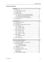
Page 9: ...nd Motion Range of Each Arm 15 2 4 Outer Dimensions 17 2 4 1 C8 A701 C8 17 2 4 2 C8 A901 C8L 18 2 4 3 C8 A1401 C8XL 19 2 5 Standard Motion Range 20 2 5 1 C8 A701 C8 20 2 5 2 C8 A901 C8L 21 2 5 3 C8 A1401 C8XL 22 2 6 Specifications 23 2 6 1 Specifications table 23 2 6 2 Option 27 2 7 How to Set the Model 28 3 Environment and Installation 29 3 1 Environmental Conditions 29 3 2 Unpacking Transportati...

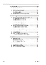
Page 10: ...of Joint 5 63 5 1 6 Max Pulse Range of Joint 6 63 5 2 Motion Range Setting by Mechanical Stops 64 5 2 1 Motion Range Setting of Joint 1 64 5 2 2 Motion Range Setting of Joint 2 65 5 2 3 Motion Range Setting of Joint 3 66 5 3 Restriction of Manipulator Operation by Joint Angle Combination 67 5 4 Coordinate System 71 5 5 Changing the Robot 72 5 6 Setting the Cartesian Rectangular Range in the XY Coo...

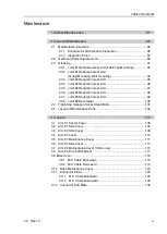
Page 11: ...ion Gear Unit 97 2 3 6 Joint 5 Reduction Gear Unit 98 2 3 7 Joint 6 Reduction Gear Unit 99 2 3 8 Joint 6 Bevel Gear 100 2 4 Tightening Hexagon Socket Head Bolts 101 2 5 Layout of Maintenance Parts 102 3 Covers 103 3 1 Arm 1 Center Cover 106 3 2 Arm 1 Side Cover 107 3 3 Arm 2 Side Cover 109 3 4 Arm 3 Cover 110 3 5 Arm 3 Maintenance Cover 111 3 6 Arm 4 Side Cover 113 3 7 Arm 4 Maintenance Cover C8XL...

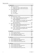
Page 12: ...nt 1 201 5 2 1 Joint 1 Replacing the Motor M C Cable Downward 201 5 2 2 Joint 1 Replacing the Reduction Gear Unit M C Cable Downward 205 5 2 3 Joint 1 Replacing the Timing Belt M C Cable Downward 208 5 2 4 Joint 1 Replacing the Electromagnetic Brake M C Cable Downward 213 6 Joint 2 216 6 1 Joint 2 Replacing the Motor 217 6 2 Joint 2 Replacing the Reduction Gear Unit 226 6 3 Joint 2 Replacing the T...

Page 13: ...the Joints 5 6 Reduction Gear Unit Set 297 10 3 Joint 6 Replacing the Timing Belt 298 10 4 Joint 6 Replacing the Electromagnetic Brake 299 11 Replacing the Battery Unit 301 11 1 Replacing the Battery Unit Lithium Battery 303 11 2 Replacing the Battery Board 305 12 Replacing the Control Board 308 12 1 Replacing the Control Board 1 309 12 2 Replacing the Control Board 2 311 13 Replacing the LED Lamp...

Page 14: ...Table of Contents xii C8 Rev 13 ...

Page 15: ...Setup Operation This volume contains information for setup and operation of the Manipulators Please read this volume thoroughly before setting up and operating the Manipulators ...

Page 16: ......

Page 17: ...nsiderations are indicated throughout the manual by the following symbols Be sure to read the descriptions shown with each symbol WARNING This symbol indicates that a danger of possible serious injury or death exists if the associated instructions are not followed properly WARNING This symbol indicates that a danger of possible harm to people caused by electric shock exists if the associated instr...

Page 18: ... or constructing the robot system without understanding the safety requirements is extremely hazardous and may result in serious bodily injury and or severe equipment damage to the robot system The Manipulator and the Controller must be used within the environmental conditions described in their respective manuals This product has been designed and manufactured strictly for use in a normal indoor ...

Page 19: ...problems in case that the Manipulator moves unexpectedly Immediately press the Emergency Stop switch whenever the Manipulator moves abnormally during operation Continuing the operation while the Manipulator moves abnormally is extremely hazardous and may result in serious bodily injury and or severe equipment change to the robot system WARNING Be sure to connect the AC power cable to a power recep...

Page 20: ...ss than 5 degrees they may get damaged early because the bearings are likely to cause oil film shortage in such situation To prevent early breakdown move the joints larger than 30 degrees for about five to ten times a day Oscillation resonance may occur continuously in low speed Manipulator motion Speed approx 5 to 20 depending on combination of Arm orientation and end effector load Oscillation ar...

Page 21: ... the Robot Controller manual for instructions on how to wire the Emergency Stop switch circuit Do not turn OFF the Controller while the Manipulator is operating If you attempt to stop the Manipulator in emergency situations such as Safeguard Open make sure to stop the Manipulator using the Emergency Stop switch of the Controller If the Manipulator is stopped by turning OFF the Controller while it ...

Page 22: ...ation cannot stop immediately after the Emergency Stop switch is pressed However time angle and distance of the free running vary by following factors Hand weight WEIGHT Setting ACCEL Setting Workpiece weight SPEED Setting Posture etc Approximate time and distance of the free running are as follow Conditions of Measurement C8 series ACCEL Setting 100 SPEED Setting 100 Load kg 8 WEIGHT Setting 8 Ro...

Page 23: ...lease unit Follow the method when you just unpack the delivered boxes or when the Controller does not start up yet 1 5 2 Moving the arm using the software Follow the method when you can use the software While the electromagnetic brake is ON such as in emergency mode you cannot move any arm by pushing manually Arm Motion Joint 1 Base Arm 1 Lower Arm Arm 2 Arm 4 Joint 6 Joint 3 Joint 4 Joint 5 Arm 6...

Page 24: ...nt damage to and or malfunction of the Manipulator EPSON RC After releasing the Emergency Stop switch execute the following command in Command Window Reset Brake Off the number from 1 to 6 corresponding to the arm whose brake will be turned off Execute the following command to turn on the brake again Brake On The number from 1 to 6 corresponding to the arm whose brake will be turned on 1 6 Precaut...

Page 25: ... B Do not enter the work space when the Manipulator is operating It is extremely hazardous since the Arm may collide and cause serious safety problems C Do not touch the current carrying parts inside the Manipulator while the power is ON It may cause electrical shock D When releasing the brakes be careful of the arm falling due to its own weight This warning label is attached on the Manipulator an...

Page 26: ...caught when bringing your hand close to moving parts Location Warning Label Note Location Label G HOT Be careful not to burn yourself H I Location of Labels Top View Back View Lateral View Front View C C C C C C A B C H Cable Downward model Bottom View C Lateral View D E F C I G G Figure C8 A1401 C8XL ...

Page 27: ... 0 48 s C8 A901 C8L About 0 35 s About 0 43 s About 0 50 s C8 A1401 C8XL About 0 53 s About 0 62 s About 0 72 s Slim Body High space efficiency Less interference with peripherals walls and ceiling permits more compact installation The system cost and installation cost can be reduced Manipulator weight C8 A701 C8 49 kg 108 lbs C8 A901 C8L 52 kg 115 lbs C8 A1401 C8XL 62 kg 137 lbs Skillful Wrist Com...

Page 28: ... Table Top mounting R Ceiling mounting W Wall mounting M C cable installation direction Cable backward B Cable downward Environment S Standard model C Cleanroom ESD electrostatic discharge model P Protection model IP67 Brake equipment 1 Brakes on all joints Arm length 7 710 mm C8 A701 C8 9 900 mm C8 A901 C8L 14 1400 mm C8 A1401 C8XL Example ...

Page 29: ...int 2 The lower arm swings Joint 3 The upper arm swings Joint 4 The wrist revolves Joint 5 The wrist swings Joint 6 The hand rotates Figure C8 A701 C8 When the LED lamp is lighting or the Controller power is on current is being applied to the Manipulator The LED lamp may not be seen depending on the Manipulator s posture Be very careful Performing any work with the power ON is extremely hazardous ...

Page 30: ...lean room model Exhaust port For ø12 mm pneumatic tube Cable downward model Power cable Signal cable Standard model Cover Clean room model Exhaust port For ø12 mm pneumatic tube User cable connector 15 pin D sub connector For ø6 mm pneumatic tubes Air1 Air2 F sensor cable connector Ethernet cable connector Cable backward model Cable downward model Signature label Serial No of Manipulator Bolt hole...

Page 31: ...Setup Operation 2 Specifications C8 Rev 13 17 2 4 Outer Dimensions Unit mm 2 4 1 C8 A701 C8 ...

Page 32: ...Setup Operation 2 Specifications 18 C8 Rev 13 2 4 2 C8 A901 C8L ...

Page 33: ...Setup Operation 2 Specifications C8 Rev 13 19 2 4 3 C8 A1401 C8XL ...

Page 34: ...m top with Joint 3 declining 61 Joint 1 center P point center 2 P point from top with Joint 3 tilting up 202 Joint 1 center P point center 3 P point from lateral with Joint 3 declining 61 Joint 2 center P point center 4 P point from lateral with Joint 3 tilting up 202 Joint 2 center P point center CAUTION Pay attention to the arm pose of the basic arms Arms 1 2 and 3 when operating the Manipulator...

Page 35: ...enter P point center 2 P point from top with Joint 3 tilting up 202 Joint 1 center P point center 3 P point from lateral with Joint 3 declining 61 Joint 2 center P point center 4 P point from lateral with Joint 3 tilting up 202 Joint 2 center P point center CAUTION Pay attention to the arm pose of the basic arms Arms 1 2 and 3 when operating the Manipulator Arm 5 moves keeping a constant angle reg...

Page 36: ...center P point center 2 P point from top with Joint 3 tilting up 202 Joint 1 center P point center 3 P point from lateral with Joint 3 declining 61 Joint 2 center P point center 4 P point from lateral with Joint 3 tilting up 202 Joint 2 center P point center CAUTION Pay attention to the arm pose of the basic arms Arms 1 2 and 3 when operating the Manipulator Arm 5 moves keeping a constant angle re...

Page 37: ...s 1 to 6 0 02 mm 0 03 mm 0 05 mm Max motion range Joint 1 240 Joint 2 158 to 65 158 to 65 135 to 55 Joint 3 61 to 202 Joint 4 200 Joint 5 135 Joint 6 360 Max pulse range Joint 1 9507090 10695600 15736800 Joint 2 6245685 to 2569428 6903178 to 2839915 10616940 to 4325420 Joint 3 1776754 to 5883677 2220949 to 7354618 3997696 to 13238272 Joint 4 5461400 Joint 5 3932280 Joint 6 6553800 Resolution Joint...

Page 38: ...x setting values SPEED 3 100 ACCEL 10 5 5 120 120 SPEEDS 50 2000 ACCELS 11 200 35000 120 25000 FINE 10000 10000 10000 10000 10000 10000 130000 130000 130000 130000 130000 130000 WEIGHT 3 8 INERTIA 0 03 0 15 Safety standard CE Marking EMC Directive Machinery Directive KC Marking KCs Marking UL standards In case of UL specification UL1740 ANSI RIA R15 06 NFPA 79 1 Mounting types other than Table Top...

Page 39: ...sibility of dust water and water soluble cutting oil falling of the Manipulator exists However please be careful of the following The Manipulator is not rust proofed Do not use the Manipulator in environment where corrosive liquids exist Fluids that deteriorate the sealing materials such as organic solvents acids alkalis and chlorine cutting fluids cannot be used The Manipulator cannot be used for...

Page 40: ... value varies depending on the load Refer to the table below for details Setting the value which exceeds the maximum AccelS causes an error In such a case check the setting value Maximum AccelS setting value Table Top mounting Ceiling mounting 40000 35000 30000 25000 20000 15000 10000 5000 0 2 4 6 8 kg End effector weight 30000 20000 35000 13000 12000 C8 A701 C8 C8 A901 C8L C8 A1401 C8XL 17000 110...

Page 41: ...a mounting tool common for C3 and C4 series Brake release box 1 For EU power supply voltage 200 V short connector included For US JP power supply voltage 100 V short connector included Short connector for the brake release box 1 When using the brake release box with C8 series it is necessary to connect the short connector to the M C power cable or connect the M C power cable with the Controller Th...

Page 42: ...and or cause safety problems If the custom specifications number MT is described on MODEL of the signature label S N label the Manipulator has custom specifications A label with only the custom specifications number may be attached depending on shipment time The custom specifications may require a different configuration procedure check the custom specifications number MT and contact the supplier ...

Page 43: ...es Keep away from water Keep away from shock or vibration Keep away from sources of electric noise 1 The ambient temperature conditions are for the Manipulators only For the Controller which the Manipulator is connected to refer to the Robot Controller manual When using the Manipulators in inadequate environments that do not meet the above conditions please contact the distributor For the Protecti...

Page 44: ...inside the Manipulator If your requirements specify that the Manipulator handles food please the supplier of your region to check whether the Manipulator will damage the food or not The Manipulator cannot be used in corrosive environments where acid or alkaline is used In a salty environment where the rust is likely to gather the Manipulator is susceptible to rust The Controller used with the Prot...

Page 45: ...hands fingers or feet caught as the Manipulator may fall To transport the Manipulator secure it to the delivery equipment or have at least 2 people to hold it by hand Also do not hold the bottom of the base the screened parts in the figure Holding these parts by hand is extremely hazardous and may cause your hands and fingers caught Figure C8 A901 C8L DO NOT hold the bottom of the base by hand Man...

Page 46: ...e the mechanical stops if using them to limit the motion range For details on the motion range refer to the Setup Operation 5 2 Motion Range Setting by Mechanical Stops 2 Unscrew the anchor bolts Then remove the Manipulator from the base table 3 Position the Manipulator as shown in the figure Then secure the Manipulator to the delivery equipment or have at least 2 people to carry the Manipulator R...

Page 47: ...ge on the covers and arms it is recommended to protect the contacting parts of the wire and arm with a cloth Be very careful not to damage the covers since they are made of plastic Holes for eye bolt 2 M12 depth 25 Figure C8 A1401 C8XL Locations of the screw holes for eyebolts are common to all models Manipulator weight C8 A701 C8 C8 A901 C8L C8 A1401 C8XL Standard Cleanroom 49 kg 108 lbs 52 kg 11...

Page 48: ...eaching points Space for maintenance and inspections for installing jigs Space for cables The minimum bend radius of the power cable is 90 mm When installing the cable be sure to maintain sufficient distance from obstacles In addition leave enough space for other cables so that they are not bent forcibly In case of C8 A1401 C8XL Make sure to leave 35 mm or more space around the fan cover Unit mm 3...

Page 49: ...Setup Operation 3 Environment and Installation C8 Rev 13 35 C8 A901 C8L ...

Page 50: ...Setup Operation 3 Environment and Installation 36 C8 Rev 13 C8 A1401 C8XL 3 3 2 Cable Downward Model The following part differs from the cable backward model C8 A701 B C8 C8 A901 B C8L C8 A1401 B C8XL ...

Page 51: ...nd may result in serious bodily injury and or severe equipment damage to the robot system as the Manipulator may fall down Before installing and operating the Manipulator make sure that all parts of the Manipulator are in place and have no external defects Missing or defective parts may cause improper operation of the Manipulator Improper operation of the Manipulator is extremely hazardous and may...

Page 52: ... as follows Model number C8 A701 C8 A901 C8 A1401 Model name C8 C8L C8XL Max Horizontal rotating torque N m 1 600 1 800 2 600 Max Horizontal reaction force N 1 200 1 300 1 300 Max Vertical rotating torque N m 1 900 2 200 3 400 Max Vertical rotating torque N 6 600 6 000 7 800 The plate for the Manipulator mounting face should be 30 mm thick or more and made of steel to reduce vibration The surface ...

Page 53: ...e cleanroom follow the steps below before the installation 1 Unpack the Manipulator outside of the cleanroom 2 Secure the Manipulator to delivery equipment such as a pallet with bolts so that the Manipulator does not fall over 3 Wipe off the dust on the Manipulator with a little alcohol or distilled water on a lint free cloth 4 Transport the Manipulator into the cleanroom 5 Secure the Manipulator ...

Page 54: ...th the power ON is extremely hazardous and may result in electric shock and or malfunction of the robot system Grounding the Manipulator is done by connecting with the Controller However it is recommended to use the grounding hole on the base to ground directly for more secure grounding If the ground wire is improperly connected to ground it may result in the fire or electric shock When connecting...

Page 55: ... the signal connector of the M C cables to the Controller Grounding WARNING Ground resistance must be 100 Ω or less Improper ground resistance may result in fire and or electric shock Do not use the ground line for the Manipulator in common with other ground lines or grounding electrodes for other electric power motor power welding devices etc Using the ground line for the Manipulator in common wi...

Page 56: ...r Detail of B A Detail of A Cable backward model Standard model Cover Clean room model Exhaust port One touch fitting for ø12 mm pneumatic tube ワンタッチ継手 B Force Sensor cable connector Ethernet cable connector Force Sensor cable connector Ethernet cable connector User cable connector 15 pin D sub connector One touch fitting for ø6 mm pneumatic tube Air1 Air2 Figure C8 A701 C8 Power cable Signal cabl...

Page 57: ...lamp Hood HRS HDA CTH 4 40 10 Connector setscrew 4 40 UNC Two parts are attached for each Attached connector for the user wires protection model Maker Standard 15 pin Connector HARTING 09 67 015 5615 Solder type Clamp Hood HARTING 09 67 015 0538 Connector setscrew 4 40 UNC Two parts are attached for each 8 pin RJ45 Cat 5e or equivalent For the standard and cleanroom model Manipulators commercially...

Page 58: ...ole size for installing the Arm 4 fitting M6 For the protection model see the following precautions as well CAUTION Be sure to use IP67 compliant wires and tubes when using the Manipulator under special environmental conditions adverse condition with dust and oily smoke Using unprotected wires and tubes may cause equipment damage to and or malfunction of the Manipulator as proper operation of the ...

Page 59: ...ibration At the time of shipment the basic orientation of the Manipulator shown below is set as the origin position After installing the Manipulator and setup the operating environment move the Manipulator to the origin position and check if it moves to the basic position properly To make the Manipulator move to the origin position select Tool Robot Manager Control Panel and click Home If the gap ...

Page 60: ...switch or the safety features of the robot system Wrist Flange Arm 6 Attach an end effector to the end of the Arm 6 using the M5 bolts Layouts When you operate the Manipulator with an end effector the end effector may interfere with the Manipulator body depending on the outer diameter of the end effector the size of the work piece or the position of the arms When designing your system layout pay c...

Page 61: ...ctors C8 Rev 13 47 C8 A701 C8 C8 A901 C8L Unit mm Rotation Center of the Upper Arm Arm 3 Deck Arm 5 Deck Rotation Center of the Upper Arm Arm 3 Deck Arm 5 Deck C8 A1401 C8XL Rotation Center of the Upper Arm Arm 3 Deck Arm 5 Deck ...

Page 62: ...ng parameters makes the operation of the Manipulator optimal reduces vibration to shorten the operating time and improves the capacity for larger loads In addition it reduces persistent vibration produced when the inertia moment of the end effector and work piece is bigger The allowable load for C8 series Manipulators is 8 kg at the maximum Due to the limitations of the moment and inertia moment s...

Page 63: ...vity of load from the Arm 5 rotation center mm Center of gravity of load from the Arm 6 rotation center mm 300 250 200 150 100 50 0 0 50 100 150 200 250 300 1 kg 2 kg 3 kg 4 kg 5 kg 6 kg 7 kg 8 kg Max Eccentric Quantity of Load Distance between the joint rotation center and the load s center of gravity Joint 1 kg 2 kg 3 kg 4 kg 5 kg 6 kg 7 kg 8 kg 4 300 mm 300 mm 300 mm 300 mm 300 mm 280 mm 242 mm...

Page 64: ... the maximum payload The C8 series Manipulators can operate without limitations on the condition unless and until the load exceeds this maximum payload Always set the Weight parameters of the WEIGHT command according to the load Setting a value that is smaller than the actual load may cause errors excessive shock insufficient function of the Manipulator and or shorten the life cycle of parts mecha...

Page 65: ...on the fore end of Arm 6 C8 A1401 C8XL Arm 3 Deck Arm 5 Deck Load on the fore end of Arm 6 Details of the deck 2 M4 depth8 4 M4 depth8 Arm 5 Deck Arm 3 Deck Unit mm When you attach the equipment to the decks on the upper arm convert its weight into equivalent weight assuming that the equipment is attached to the end of theArm 6 Then this equivalent weight added to the load will be a Weight paramet...

Page 66: ... deck Length of the upper arm 315 mm Distance between the Joint 3 and the center of gravity of the air valve on the Arm 3 deck mm Distance between the Joint 3 and the center of gravity of the camera on the Arm 5 deck mm Example The fore end of the Arm 6 is 730 mm L away from the Joint 3 of C8 A1401 C8XL Load on the fore end of Arm 6 is 5 kg Mw Load on the Arm 3 deck is 1 5 kg Ma The deck is 0 mm L...

Page 67: ... Acceleration Deceleration 130 65 45 35 100 C8 A901 C8L 140 120 100 80 60 40 20 0 2 4 6 8 kg Weight Parameter 110 100 100 Speed 100 100 100 Acceleration Deceleration 130 60 45 35 100 C8 A1401 C8XL 140 120 100 80 60 40 20 105 100 100 100 100 100 120 72 51 45 100 0 2 4 6 8 kg Weight Parameter Speed Acceleration Deceleration Maximum AccelS setting value varies depending on Weight setting value For mo...

Page 68: ...nertia moment Setting a value that is smaller than the actual inertia moment may cause errors excessive shock insufficient function of the Manipulator and or shorten the life of parts mechanisms The acceptable inertia moment of load for C8 series Manipulators is 0 03 kg m2 nominal rating and 0 15 kg m2 maximum Change the setting of the inertia moment according to the inertia moment of the load usi...

Page 69: ...imum When the eccentric quantity of the load exceeds the rating change the setting of eccentric quantity parameter using the INERTIA command After changing the setting the maximum acceleration deceleration speed of Manipulator corresponding to eccentric quantity is set automatically Position of Load s Center of Gravity Rotation Center a b Eccentric Quantity 300 mm or less Flange a b To set the par...

Page 70: ... m2 Inertia moment 150 140 120 100 80 60 40 20 140 100 50 15 The percentage in the graph is based on the acceleration deceleration at rated eccentricity 0 03 kg m2 as 100 Automatic setting by eccentricity setting common to C8 series 120 100 80 60 40 20 0 100 200 300 mm Eccentricity 50 25 15 100 100 The percentage in the graph is based on the acceleration deceleration at rated eccentricity 50 mm as...

Page 71: ... Moment of Inertia of End Effector a Moment of Inertia of Work Piece b Moment of Inertia of Work Piece c Whole Moment of Inertia The methods for calculating the inertia moment for a b and c are shown in this and the next page Figure out the whole inertia moment using the basic formulas below a Inertia moment of a rectangular parallelepiped h b L m Rectangular Parallelepiped s Center of Gravity Rot...

Page 72: ...Setup Operation 4 End Effectors 58 C8 Rev 13 c Inertia moment of a sphere m r 2 m L2 2 5 Sphere s Center of Gravity r m L Rotation Center ...

Page 73: ...ng The acceleration deceleration of Arm 6 are controlled according to the inertia moment set by the INERTIA command The acceleration deceleration of the whole Manipulator are controlled according to the eccentricity set by the INERTIA command The more the inertia moment and eccentricity of the load increase the more the acceleration deceleration are reduced Auto Acceleration Deceleration According...

Page 74: ...nged due to layout efficiency or safety follow the descriptions in 5 1 through 5 4 to set the range 5 1 Motion Range Setting by Pulse Range for Each Joint Pulses are the basic unit of Manipulator motion The motion range of the Manipulator is controlled by the pulse range the lower limit and the upper limit of each axis Pulse values are read from the encoder output of the servo motor The pulse rang...

Page 75: ...ion direction C8 A701 C8 C8 A901 C8L C8 A1401 C8XL Angle 240 Pulse pulse 9507090 10695600 15736800 5 1 2 Max Pulse Range of Joint 2 Pulse values in clockwise direction are positive and values in counterclockwise direction are negative Arm 2 0 pulse position direction direction C8 A701 C8 C8 A901 C8L C8 A1401 C8XL Angle 158 to 65 135 to 55 Pulse pulse 6245685 to 2569428 6903178 to 2839915 10616940 ...

Page 76: ...rection direction C8 A701 C8 C8 A901 C8L C8 A1401 C8XL Angle 61 to 202 Pulse pulse 1776754 to 5883677 2220949 to 7354618 3997696 to 13238272 5 1 4 Max Pulse Range of Joint 4 From the angle of arm end clockwise pulse values are positive and counterclockwise pulse values are negative The max pulse range of the Arm 4 is common to C8 series Manipulators Arm 4 0 pulse position 5461400 pulse 5461400 pul...

Page 77: ... max pulse range of theArm 5 is common to C8 series Manipulators Arm 5 0 pulse position 3932280 pulse 3932280 pulse deg 5 1 6 Max Pulse Range of Joint 6 From the angle of arm end clockwise pulse values are positive and counterclockwise pulse values are negative The max pulse range of the Arm 6 is common to C8 series Manipulators Arm 6 0 pulse position 6553800 pulse 6553800 pulse deg ...

Page 78: ...ration 5 1 Motion Range Setting by Pulse Range for All Arms Be sure to set the pulse range not to exceed the setting angles of the mechanical stop 5 2 1 Motion Range Setting of Joint 1 Install the adjustable mechanical stop J1 to the threaded hole corresponding to the angle you want to set Normally the mechanical stop is not installed Hexagon socket head cap bolt M12 30 2 bolts Tightening torque 4...

Page 79: ...tall the adjustable mechanical stop C8 C8L_J2 Joint 2 standard motion range 158 to 65 Hexagon socket head cap bolt M10 35 1 bolt Tightening torque 32 0 1 6 N m 326 16 kgf cm d e d e Angle 158 30 158 65 Pulse pulse C8 A701 C8 6245685 1185890 6245685 2569428 C8 A901 C8L 6903178 1310730 6903178 2839915 Adjustable mechanical stop C8 C8L_J2 Applied Applied standard ...

Page 80: ...6940 4325420 Adjustable mechanical stop C8XL_J2 Applied Applied standard 5 2 3 Motion Range Setting of Joint 3 Remove the mechanical stop installed as standard and install the adjustable mechanical stop J3 Joint 3 standard motion range 61 to 202 Hexagon socket head cap bolt M6 15 2 bolts Tightening torque 13 0 0 6 N m 133 6 kgf cm f g f g Angle 51 192 61 202 Pulse pulse C8 A701 C8 1485483 5592406 ...

Page 81: ...or stops when the joint angles of the Arm are within the gray areas in the following figure The restriction to Manipulator operation is enabled During CP motion command execution When you attempt to execute the motion command for moving the Manipulator to a target point or pose in the specified motion range The restriction to the Manipulator operation is disabled The Arms of the Manipulator moment...

Page 82: ...3 50 deg J1 50 deg Joint 2 Angle Joint 3 Angle 120 deg J1 50 deg or 50 deg J1 120 deg Joint 2 Angle Joint 3 Angle 240 deg J1 120 deg or 120 deg J1 240 deg Joint 2 Angle Joint 3 Angle Combination of Joints 1 and 2 240 deg J1 100 deg or 100 deg J1 240 deg Joint 1 Angle Joint 2 Angle deg ...

Page 83: ...3 50 deg J1 50 deg Joint 2 Angle Joint 3 Angle 120 deg J1 50 deg or 50 deg J1 120 deg Joint 2 Angle Joint 3 Angle 240 deg J1 120 deg or 120 deg J1 240 deg Joint 2 Angle Joint 3 Angle Combination of Joints 1 and 2 240 deg J1 100 deg or 100 deg J1 240 deg Joint 1 Angle Joint 2 Angle deg ...

Page 84: ...Combination of Joints 2 and 3 110 deg J1 110 deg Joint 2 Angle Joint 3 Angle 140 deg J1 110 deg or 110 deg J1 140 deg 240 deg J1 220 deg or 220 deg J1 240 deg Joint 2 Angle Joint 3 Angle 220 deg J1 140 deg or 140 deg J1 220 deg Joint 2 Angle Joint 3 Angle deg ...

Page 85: ...e manual Table Top mounting Ceiling mounting Wall mounting Z X Y Z X Y X Y Z X X Y Y BASE setting is suitable for install the robot obliquely BASE setting can change a specific coordinate system of the robot and match the World coordinate system of the Jog Teach and the coordinate system of the equipment For procedure of the BASE setting refer to SPEL Language Reference BASE Command With BASE sett...

Page 86: ...on data by following the procedure below 1 Select the EPSON RC 7 0 menu Setup System Configuration 2 Select Controller Robots Robot Calibration from the tree list Then click Save 1 Select the EPSON RC 7 0 menu Setup System Configuration 2 Select Controller Robots Robot from the tree list 3 Click the Change button The following dialog box will be displayed 4 Input the robot name and serial number p...

Page 87: ...M setting The limited Manipulator operation area is defined so that the end effector does not interfere with the rear side of the Manipulator The XYLIM setting that you can determines the upper and lower limits of the X and Y coordinates The limited Manipulator operation area and the XYLIM setting apply only to the software Therefore these settings do not change the physical range The maximum phys...

Page 88: ...power to the Controller and the brake release unit Inserting and removing the connector while the power is ON may result in electrical shock CAUTION Normally release the brake of joints one by one Take extra care if you need to release the brakes of two or more joints simultaneously Releasing the brakes of two or more joints simultaneously may cause hands and fingers to be caught and or equipment ...

Page 89: ...nnot be released and it may cause damage on them After using the brake release unit be sure to connect the external short connector to the Manipulator or check connection of the connector for the brake release unit Keep the external short connector Otherwise you cannot release the brakes If you turn ON the brake release unit while the brake release switch is being pressed an unintended arm may mov...

Page 90: ...ler Go to the step 3 3 Remove the external short connector External short connector 4 Connect the brake release unit to the connector of the connection cable Connection cable Connector Remove the brake release unit 1 Turn OFF the brake release unit 2 Remove the power cable of the brake release unit 3 Disconnect the brake release unit from the connector of the connection cable 4 If the M C short co...

Page 91: ...perating the Manipulator it may lead to the breakdown of the Manipulator or you may get your hand or fingers caught Power cable Power switch Brake release switches Power lamp 1 Plug the power cable into the brake release unit 2 Plug the power cable into the power supply plug 3 Turn ON the brake release unit When the brake release unit is enabled the power lamp lights up 4 Press the switch of the a...

Page 92: ...s included Qty A Camera adapter plate 1 B Camera mid plate 1 C Camera base plate 1 D Hexagon socket head screws M4 12 6 E Hexagon socket head screws M4 20 2 F Plain washer for M4 small washer 2 Installation Mounting holes for the camera base plate on the C8 series Manipulator Camera base plate mounting hole For the installation steps refer to the following manual EPSON RC Option Vision Guide 7 0 H...

Page 93: ... mounting position of camera mid plate and the camera you are using The table below shows the motion range reference values based on the available cameras for this option and the mounting positions of the camera mid plate The values in the table may vary depending on how to secure the cables By changing the Y position you can extend the distance from the end effector mounting surface to the camera...

Page 94: ...th 12 at 90 pitch depth 5 depth 4 To mount the ISO flange 1 Press fit the pin to the Arm 6 end flange Pin projection 4 mm from the flange Pin 2 Align the pin and the pin hole on the flange and then mount the flange Hexagon socket head screw 4 M5 15 Hexagon socket head screw 4 M5 15 Flange 3 Press fit the pin to the installed flange Pin protrusion 4 mm from the flange Pin 4 Align the pin and the pi...

Page 95: ...ical Stops Adjustable mechanical stop J1 Item Qty Adjustable mechanical stop J1 1 Hexagon socket head screw M12 30 2 Adjustable mechanical stop C8 C8L_J2 Item Qty Adjustable mechanical stop C8 C8L_J2 1 Hexagon socket head screw M10 35 1 Adjustable mechanical stop C8XL_J2 Item Qty Adjustable mechanical stop C8XL_J2 1 Hexagon socket head screw M10 35 2 Adjustable mechanical stop J3 Item Qty Adjustab...

Page 96: ...er Standard Connector 2 JAE DA 15PF N Solder type Clamp hood 2 HRS HDA CTH 4 40 10 Connector setscrew 4 40 UNC Attached to standard and cleanroom model Manipulators as standard The parts can be additionally purchased in case of lost or shortage Waterproof User Connector Kit D sub Item Qty Manufacturer Standard Connector 2 HARTING 09 67 015 5615 Solder type Clamp hood 2 HARTING 09 67 015 0538 Conne...

Page 97: ...Maintenance This volume contains maintenance procedures with safety precautions for C8 series Manipulators ...

Page 98: ......

Page 99: ...oblems as the Manipulator may move even it seems to be stopped When you check the operation of the Manipulator after replacing parts be sure to check it while you are outside of the safeguarded area Checking the operation of the Manipulator while you are inside of the safeguarded area may cause serious safety problems as the Manipulator may move unexpectedly Before operating the robot system make ...

Page 100: ...otors Be careful when performing maintenance 2 General Maintenance This chapter describes maintenance inspection procedures Performing maintenance inspection properly is essential to prevent trouble and ensure safety Be sure to perform the maintenance inspections in accordance with the schedule 2 1 Maintenance Inspection 2 1 1 Schedule for Maintenance Inspection Inspection points are divided into ...

Page 101: ...ess of connectors If the connectors are loosen push it securely or tighten External connectors on Manipulator on the connector plates etc Manipulator cable unit Visually check for external defects Clean up if necessary External appearance of Manipulator External cables Check for bends or improper location Repair or place it properly if necessary Safeguard etc Check tension of timing belts Tighten ...

Page 102: ...heck whether unusual sound or vibration occurs Whole Measure the accuracy repeatedly by a dial gauge Whole When brake release unit is installed Connect the brake release unit and check the sound of the electromagnetic brake with the brake released If there is no sound replace the brake When brake release unit is not installed Execute Brake off command brake off joint from the command window of the...

Page 103: ...erhauls is 20 000 operation hours of the Manipulator as a rough indication However it may vary depending on usage condition and degree of the load such as when operated with the maximum motion speed and maximum acceleration deceleration in continuous operation applied on the Manipulator For the EPSON RC 7 0 Ver 7 2 x or later firmware Ver 7 2 x x or later the recommended replacement time for the p...

Page 104: ...ontroller Status button to open the Browse For Folder dialog 3 Select the folder where the information is stored 4 Click OK to view the Controller Status Viewer dialog 5 Select Robot from the tree menu on the left side For the parts subject to overhaul refer to Maintenance 17 Maintenance Parts List For details of replacement of each part refer to the Maintenance section Please contact the supplier...

Page 105: ... will be required for the repairs If grease gets into your eyes mouth or on your skin follow the instructions below If grease gets into your eyes Flush them thoroughly with clean water and then see a doctor immediately If grease gets into your mouth If swallowed do not induce vomiting See a doctor immediately If grease just gets into your mouth wash out your mouth with water thoroughly If grease g...

Page 106: ...lts Cross point screwdriver 2 1 For cross recessed head screws Flat head screwdriver 1 For grease plug Before greasing move the Manipulator so that the grease inlet is not directed down Do not remove the grease plug while the grease inlet is directed down Otherwise the oil content separated from the grease may leak out Do not use any tool to install and remove the grease nipple and grease line ext...

Page 107: ... inlet located inside the Arm 1 3 Attach the grease nipple to the Joint 1 grease inlet 4 Inject grease from the grease nipple using a grease gun Grease SK 1A Grease amount 11g 5 Remove the grease nipple from the Joint 1 grease inlet 6 Attach the grease plug to the Joint 1 grease inlet If the grease plug is damaged or deteriorated replace it with a new one 7 Install the Arm 1 side cover For details...

Page 108: ...ig and grease nipple to the Joint 1 grease inlet 5 Inject grease from the grease nipple using a grease gun Grease SK 1A Grease amount 11g 6 Remove the grease nipple and grease line extension jig from the Joint 1 grease inlet 7 Attach the grease plug to the Joint 1 grease inlet If the grease plug is damaged or deteriorated replace it with a new one 8 Apply a thin coat of grease SK 1A to the O ring ...

Page 109: ...ove the grease plug from the Joint 2 grease inlet of the Arm 1 2 Attach the grease nipple to the Joint 2 grease inlet 3 Inject grease from the grease nipple using a grease gun Grease SK 1A Grease amount 6g C8 C8L 12g C8XL 4 Remove the grease nipple from the Joint 2 grease inlet 5 Attach the grease plug to the Joint 2 grease inlet If the grease plug is damaged or deteriorated replace it with a new ...

Page 110: ...nlet of the Arm 2 2 Attach the grease nipple to the Joint 3 grease inlet 3 Inject grease from the grease nipple using a grease gun Grease SK 1A Grease amount 3g 4 Remove the grease nipple from the Joint 3 grease inlet 5 Attach the grease plug to the Joint 3 grease inlet If the grease plug is damaged or deteriorated replace it with a new one ...

Page 111: ...ole located near the label with 4 printed is the Joint 4 grease inlet The grease inlet position differs depending on the model Carefully identify the correct position 3 Inject grease from the grease nipple using a grease gun Grease SK 1A Grease amount 2g 4 Remove the grease nipple from the Joint 4 grease inlet 5 Attach the grease plug to the Joint 4 grease inlet If the grease plug is damaged or de...

Page 112: ...r the label with 5 printed is the Joint 5 grease inlet Be careful not to confuse it with the Joint 6 grease inlet 3 Inject grease from the grease nipple using a grease gun Grease SK 1A Grease amount 1g Be careful not to mix with the grease used in the Joint 6 SK 2 4 Remove the grease nipple from the Joint 5 grease inlet 5 Attach the grease plug to the Joint 5 grease inlet If the grease plug is dam...

Page 113: ... the label with 6 printed is the Joint 6 grease inlet Be careful not to confuse it with the Joint 5 grease inlet 3 Inject grease from the grease nipple using a grease gun Grease SK 2 Grease amount 0 5g Be careful not to mix with the grease used in the Joint 5 SK 1A 4 Remove the grease nipple from the Joint 6 grease inlet 5 Attach the grease plug to the Joint 6 grease inlet If the grease plug is da...

Page 114: ...ly grease to the mating surface of the bevel gear inside the Arm 5 Grease SK 2 Grease amount 2g 4 Apply a thin coat of grease SK 2 to the O ring Fit the O ring into the base groove Do not allow the O ring to come out of the groove If the O ring is swollen damaged or deteriorated replace it with a new one 5 Install the Arm 5 grease inlet cover Hexagon socket head cap bolts 4 M3 6 Tightening torque ...

Page 115: ...set screw M3 2 0 0 1 N m 21 1 kgf cm Set Screw Tightening Torque M4 4 0 0 2 N m 41 2 kgf cm M4 2 4 0 1 N m 26 1 kgf cm M5 8 0 0 4 N m 82 4 kgf cm M5 3 9 0 2 N m 40 2 kgf cm M6 13 0 0 6 N m 133 6 kgf cm M6 8 0 0 4 N m 82 4 kgf cm M8 32 0 1 6 N m 326 16 kgf cm M10 58 0 2 9 N m 590 30 kgf cm M12 100 0 5 0 N m 1 020 51 kgf cm It is recommended to fasten the bolts aligned on a circumference in a crissc...

Page 116: ...1 Reduction gear unit Joint 3 Reduction gear unit Joint 3 Motor Electromagnetic brake Joint 3 Timing belt LED lamp Joint 5 Motor Electromagnetic brake Joint 5 Timing belt Joint 6 Motor Electromagnetic brake Joint 6 Timing belt Joint 5 6 Reduction Gear Unit Set Joint 4 Electromagnetic brake Joint 4 Motor Joint 4 Reduction gear unit Joint 4 Timing belt Battery board Battery Control board 2 Control b...

Page 117: ...e robot system To shut off power to the robot system disconnect the power plug from the power source Be sure to connect the AC power cable to a power receptacle DO NOT connect it directly to a factory power source Before performing any replacement procedure turn OFF the Controller and related equipment and then disconnect the power plug from the power source Performing any replacement procedure wi...

Page 118: ... cover Arm 3 maintenance cover Arm 4 D sub attachment Arm 4 side cover Arm 2 side cover Arm 1 side cover Arm 2 side cover Arm 1 side cover Arm 4 maintenance cover Arm 1 maintenance cover Figure C8 A1401 C8XL Fan C8 A1401 C8XL only Cable downward model Connector plate Connector sub plate Fan C8 A1401 B C8XL only Figure C8 A1401 B C8XL Base cover ...

Page 119: ...ter gasket 1 1665238 Protection model Side gasket 2 1665240 Arm 2 Side gasket 2 1665241 Arm 3 Cover gasket 1 1665242 Maintenance gasket 1 1665254 Arm 4 Side gasket 2 1665243 Maintenance gasket 1 1665257 D sub attachment gasket 1 1665255 Base Rear gasket 1 1665244 Bottom gasket 1 1665247 Maintenance gasket 1 1665248 Sub plate gasket 1 1665246 Installation gasket 1 1668377 Gasket For heat sink 1 169...

Page 120: ...Removal Remove the screws and then remove the Arm 1 center cover S C models Cross recessed truss head small screws 5 M4 10 P model Hexagon socket head cap bolts with captive washer 5 M4 12 Remove the Arm 1 center gasket together Installation S C models Install the Arm 1 center cover to the Manipulator Cross recessed truss head small screws 5 M4 10 Tightening torque 0 9 0 1 N m P model Install the ...

Page 121: ... in electric shock and or improper function of the robot system When routing the cables check the cable locations at removing the cover Be sure to place the cables back to their original locations Removal Remove the screws and then remove the Arm 1 side cover S C models Cross recessed truss head small screws 4 M4 10 one side P model Hexagon socket head cap bolts with captive washer 8 M4 12 one sid...

Page 122: ... side cover Install the Arm 1 side cover to the Manipulator Hexagon socket head cap bolts with captive washer 8 M4 12 one side Tightening torque 4 0 0 2 N m Be careful not to get the gasket and cables caught between the cover and the Manipulator Replace the gasket if there are flaws or deteriorations When replacing the side cover for the right side of the Arm 1 attach the electrical shock warning ...

Page 123: ... models Cross recessed truss head small screws 4 M4 10 one side P model Hexagon socket head cap bolts with captive washer 8 M4 12 one side Remove the Arm 2 side gasket together Note that the Arm 2 side covers and Arm 2 side gaskets are different between right and left Installation S C models Install the Arm 2 side cover to the Manipulator Cross recessed truss head small screws 4 M4 10 one side Tig...

Page 124: ...val Remove the screws and then remove the Arm 3 head cover S C models Cross recessed truss head small screws 4 M4 10 P model Hexagon socket head cap bolts with captive washer 4 M4 12 Remove the Arm 3 gasket together Installation S C models Install the Arm 3 cover to the Manipulator Cross recessed truss head small screws 4 M4 10 Tightening torque 0 9 0 1 N m P model Install the gasket to the grove ...

Page 125: ...proper function of the robot system When routing the cables check the cable locations at removing the cover Be sure to place the cables back to their original locations Removal 1 Before removing the Arm 3 maintenance cover move the arm to the position where you can remove the cover easily 2 Remove the screws and then remove the Arm 3 maintenance cover S C models Cross recessed truss head small scr...

Page 126: ...ance gasket Install the Arm 3 maintenance gasket to the Arm 3 maintenance cover See the figure for gasket applying points Arm 3 maintenance gasket Gasket applying point 4 Spacer 4 Arm 3 maintenance cover After applying the liquid gasket leave the gasket until the liquid gasket becomes solid and the gasket is fixed 3 Install the Arm 3 maintenance cover to the Manipulator Hexagon socket head cap bol...

Page 127: ...ons at removing the cover Be sure to place the cables back to their original locations Removal 1 Remove the screws and then remove the Arm 4 side cover S C models Cross recessed truss head small screws 7 M4 10 one side P model Hexagon socket head cap bolts with captive washer 7 M4 12 one side Remove the Arm 4 side gasket together The Arm 4 side cover and Arm 4 side gasket are the same between righ...

Page 128: ... M4 10 one side Tightening torque 0 9 0 1 N m P model Install the Arm 4 side gasket to the grove on the Arm 4 side cover Install the Arm 4 cover to the Manipulator Cross recessed truss head small screws 7 M4 12 one side Tightening torque 4 0 0 2 N m Be careful not to get the gasket and cables caught between the cover and the Manipulator Replace the gasket if there are flaws or deteriorations When ...

Page 129: ...or improper function of the robot system When routing the cables check the cable locations at removing the cover Be sure to place the cables back to their original locations Removal 1 Before removing theArm 4 maintenance cover move the arm to the position where you can remove the cover easily 2 Remove the screws and then remove the Arm 4 maintenance cover S C models Cross recessed truss head small...

Page 130: ...ance gasket Install the Arm 4 maintenance gasket to the Arm 4 maintenance cover See the figure for gasket applying points Arm 4 maintenance gasket Gasket applying point 4 Spacer 4 Arm 4 maintenance cover After applying the liquid gasket leave the gasket until the liquid gasket becomes solid and the gasket is fixed 3 Install the Arm 4 maintenance cover to the Manipulator Hexagon socket head cap bol...

Page 131: ...s and may result in electric shock and or improper function of the robot system When routing the cables check the cable locations at removing the D sub attachment Be sure to place the cables back to their original locations Removal Remove the screws and then remove the D sub attachment Hexagon socket head cap bolts 2 M4 10 P mode Remove the D sub attachment gasket together Installation S C models ...

Page 132: ...the bottom face of the base Removal Remove the bolts and then remove the base cover Hexagon socket head cap bolts 8 M4 10 P model Remove the base bottom gasket together Installation S C models Install the base cover to the Manipulator Hexagon socket head cap bolts 8 M4 10 Tightening Torque 4 0 0 2 N m P model Install the gasket to the grove on the base bottom face and then install the base cover t...

Page 133: ...may result in electric shock and or improper function of the robot system When routing the cables check the cable locations at removing the cover Be sure to place the cables back to their original locations The base cover of the M C cable downward model is located on the backside of the base C8 A701 B C8 C8 A901 B C8L Removal Remove the bolts and then remove the base cover Hexagon socket head cap ...

Page 134: ... Apply the liquid gasket to the base rear gasket Install the base rear gasket to the base cover See the figure for gasket applying points Base rear gasket Gasket Applying point 11 Spacer 11 Base cover After applying the liquid gasket leave the gasket until the liquid gasket becomes solid and the gasket is fixed 3 Install the base cover to the Manipulator Hexagon socket head cap bolts 11 M4 10 Tigh...

Page 135: ...ove the base cover and the base rear gasket Hexagon socket head cap bolts 11 M4 10 The gasket has the spacers Be careful not to lose them C8 A1401 B C8XL Installation 1 Install the spacers to the holes on the gasket 11 places 2 Apply the liquid gasket to the base rear gasket Install the base rear gasket to the base cover See the figure for gasket applying points Base rear gasket Gasket Applying po...

Page 136: ... and cables caught between the cover and the Manipulator Replace the gasket if there are flaws or deteriorations For cleanroom and protection models install the gasket between the heat sink and the base cover 4 Install the heat sink Hexagon socket head cap bolts 4 M4 15 Tightening torque 4 0 0 2 N m 5 Install the fan For details refer to Maintenance 15 Replacing the Fan NOTE NOTE ...

Page 137: ...ables check the cable locations at removing the cover Be sure to place the cables back to their original locations Removal Remove the screws and then remove the base maintenance cover S C models Cross recessed truss head small screws 6 M4 10 P model Hexagon socket head cap bolts 6 M4 10 Remove the base maintenance gasket together The gasket has the spacers Be careful not to lose them Installation ...

Page 138: ...ase maintenance gasket Gasket applying point 6 Spacer 6 Base maintenance plate After applying the liquid gasket leave the gasket until the liquid gasket becomes solid and the gasket is fixed 3 Install the base maintenance cover to the Manipulator Hexagon socket head cap bolts 6 M4 10 Tightening torque 4 0 0 2 N m Be careful not to get the gasket and cables caught between the cover and the Manipula...

Page 139: ... forcibly to push into the cover Unnecessary strain on cables may result in damage to the cables disconnection and or contact failure These are extremely hazardous and may result in electric shock and or improper function of the robot system When routing the cables check the cable locations at removing the connector plate Be sure to place the cables back to their original locations C8 A701 C8 C8 A...

Page 140: ...the liquid gasket to the base rear gasket Install the base rear gasket to the connector plate See the figure for gasket applying points Base rear gasket Gasket Applying point 11 Spacer 11 Connector plate After applying the liquid gasket leave the gasket until the liquid gasket becomes solid and the gasket is fixed 3 Install the connector plate to the Manipulator Hexagon socket head cap bolts 11 M4...

Page 141: ...ove the connecter plate and the base rear gasket Hexagon socket head cap bolts 11 M4 10 The gasket has the spacers Be careful not to lose them C8 A1401 C8XL Installation 1 Install the spacers to the holes on the gasket 11 places 2 Apply the liquid gasket to the base rear gasket Install the base rear gasket to the base cover See the figure for gasket applying points Base rear gasket Gasket Applying...

Page 142: ... and cables caught between the cover and the Manipulator Replace the gasket if there are flaws or deteriorations For cleanroom and protection models install the gasket between the heat sink and the connector plate 4 Install the heat sink Hexagon socket head cap bolts 4 M4 15 Tightening torque 4 0 0 2 N m 5 Install the fan For details refer to Maintenance 15 Replacing the Fan NOTE NOTE ...

Page 143: ...oper function of the robot system When routing the cables check the cable locations at removing the connector plate Be sure to place the cables back to their original locations Removal Remove the bolts and then remove the connector plate Hexagon socket head cap bolts 8 M4 10 P model Remove the base bottom gasket together Installation S C models Install the connector plate to the Manipulator Hexago...

Page 144: ...of the robot system When installing the connector sub plate be careful not to get the cables caught in it or bend them forcibly to push into the cover Unnecessary strain on cables may result in damage to the cables disconnection and or contact failure These are extremely hazardous and may result in electric shock and or improper function of the robot system When routing the cables check the cable ...

Page 145: ...ll the base sub plate gasket to the connector sub plate See the figure for gasket applying points Sub plate gasket Gasket applying point 4 Spacer 4 Connector sub plate After applying the liquid gasket leave the gasket until the liquid gasket becomes solid and the gasket is fixed 3 Install the connector sub plate to the Manipulator Hexagon socket head cap bolts 4 M4 10 with a seal washer Tightening...

Page 146: ...ctric shock and or malfunction of the robot system Be careful not to get any foreign substances in the Manipulator connectors and pins during maintenance Turning ON the power to the robot system when any foreign substances exist in them is extremely hazardous and may result in electric shock and or malfunction of the robot system Be sure to connect the cables properly Do not allow unnecessary stra...

Page 147: ... including a mask protective goggles and oil resistant gloves If alcohol or adhesive gets on your skin wash the area thoroughly with soap and water If alcohol or adhesive gets into your eyes or mouth flush your eyes or wash out your mouth with clean water thoroughly and then see a doctor immediately Wear protective gear including a mask protective goggles and oil resistant gloves during grease up ...

Page 148: ...or Long nose pliers 1 For removing an air tube Nippers 1 For cutting a wire tie Cross point screwdriver 2 1 For cross recessed head screws Torque rench 1 For tightening torque control Belt tension meter 1 Refer Unitta U 505 The belt tensile jig is an assembly jig Use this jig when adjusting belt tension The brake is mounted on each joint to prevent the arm from lowering due to its own weight while...

Page 149: ...over Arm 2 side covers both sides Arm 1 side covers both sides Arm 1 center cover Base maintenance cover Connector plate M C cable backward 4 Remove the two air tubes inside the base 5 Remove the two D sub connectors 6 Disconnect the cables from the base and disconnect the following connectors Connectors X11 X12 X14 BR010 BR011 X010 X020 X040 LED GS01 BT1 Hold the clip to remove 7 Disconnect the f...

Page 150: ... 2 M3 6 10 Remove the brake power supply Cross recessed head screws with washer 2 M3 6 11 Disconnect the following cables through the opening of the base D sub cable Ground wire RJ45 connector F sensor connector 12 Remove the Joint 1 motor unit For details refer to Maintenance 5 1 1 Joint 1 Replacing the Motor M C Cable Backward Removal steps 6 and 7 13 Remove the plate for preventing cable interf...

Page 151: ...ket head cap bolts 2 M3 6 15 Remove the Joint 1 timing belt 16 Remove the battery from the battery box 17 Disconnect the battery connector Hold the board by hand and pull up the battery cable to disconnect the connector 18 Remove the plate to which the battery board is fixed Hexagon socket head cap bolts 2 M4 10 NOTE ...

Page 152: ... and 5 to 9 22 Cut off the wire tie that binds the cables inside the Arm 1 and remove the connector connected to the control board 1 Connector GS01 23 Remove the Joint 1 cable fixing plate Arm 1 side Hexagon socket head cap bolts 2 M4 10 24 Disconnect the internal cables from the base side to the Arm 1 side Protect the connectors with masking tapes To protect the connector s clips To avoid adheren...

Page 153: ...1 cable brackets C2 and S2 one each and cable protection tube Hexagon socket head cap bolts 2 M3 6 C2 2 M4 10 S2 27 Remove the Arm 2 cable bracket C2 and cable protection tube Hexagon socket head cap bolts 2 M3 6 28 Remove the Arm 2 cable fixing plate Hexagon socket head cap bolts 2 M4 10 29 Cut off the wire tie that binds the cable protection coils inside the Arm 2 ...

Page 154: ... Hexagon socket head cap bolts 2 M4 8 C3A 2 M4 8 S3 33 Remove the two air tubes inside the Arm 3 Remove the air tube fittings from the air tubes The air tube fittings will be used again Be careful not to lose them 34 Remove the two ground wire terminals from the Arm 3 Cross recessed head screws with washer 2 M4 8 35 Disconnect the connectors inside the Arm 3 Connectors X141 X151 X161 BR041 BR051 X...

Page 155: ...d cap bolts 2 M4 10 38 Remove the Arm 3 cable bracket C3B Hexagon socket head cap bolts 2 M3 6 39 Remove the Arm 3 cable fixing plate 1 Hexagon socket head cap bolts 2 M4 10 40 Cut off the wire tie that binds the cable protection coils inside theArm 3 41 Disconnect the cables from the Arm 3 side to the Arm 2 side ...

Page 156: ...he connectors with a plastic bag Then pass the cable unit through the arm 43 Remove the Arm 3 cable fixing plate 2 Hexagon socket head cap bolts 2 M4 10 44 Remove theArm 3 cable bracket C4 and the cable protection sheet Hexagon socket head cap bolts 2 M3 6 C8XL Remove the cable bracket C4 and the cable protection sheet at the Arm 4 maintenance cover Hexagon socket head cap bolts 2 M3 6 ...

Page 157: ... wire tie that binds the cables of the Arm 4 47 Loosen the bolts that fix the cable protection plate attached on the Arm 4 and disconnect the cables Hexagon socket head cap bolts 2 M4 10 48 Remove the ground wire terminals from the cable protection plate Cross recessed head screws with washer 4 M4 8 ...

Page 158: ...ith the Joint 5 motor unit will be used again Be careful not to lose them 50 Remove the Arm 4 D sub attachment Hexagon socket head cap bolts 2 M4 10 For details refer to Maintenance 3 Covers 51 Remove the following parts from the Arm 4 D sub attachment S C models D sub connector D sub connector fixing plate P model D sub connector 52 Remove the Arm 4 cable fixing plate Hexagon socket head cap bolt...

Page 159: ...Maintenance 4 Cable Unit C8 Rev 13 145 54 Disconnect the following cables that have no relays from the Arm 4 side to the Arm 3 side Ethernet cable X052 X062 cable Ground wire green yellow ...

Page 160: ...3 sheets 25 mm 120 mm 2 Remove the Ethernet cable from the connector Protect the cable ends with masking tapes to prevent the clip from damage 3 Remove the locking screws and nuts of the D sub connector The screws and nuts will be used again for fixing the connector Be careful not to lose them 4 Disconnect the following connectors to separate the cables Connectors X051 X061 X151 X161 XGND BR051 BR...

Page 161: ...the connector end Air tube 210 mm from the end 130 mm 6 Pass the separated cable unit base side from theArm 2 to theArm 1 To protect the connectors and facilitate the work first cover the connectors with a plastic bag Then pass the cable unit through the arm Pass the following cables that have no relays through the arm to the Arm 3 side Ethernet cable X052 X062 cable Ground wire green yellow ...

Page 162: ...rt the connectors through the braid tube as shown in the photo and fix the tube with the wire tie so that connectors are not to be pulled out Then pull the braid tube from the Arm 4 side while pushing the cables from the Arm 3 side to pass the cables through See the photo 8 Pass the separated cable unit Arm 4 side from theArm 4 to theArm 3 C8 C8L No silicone tube is provided C8XL Silicone tube is ...

Page 163: ...photo 9 Install the cable fixing plate to the Arm 4 Hexagon socket head cap bolts 2 M4 10 Tightening torque 4 0 0 2 N m 10 Use a cable bracket C4 to fix the cables Hexagon socket head cap bolts 2 M3 6 Tightening torque 2 4 0 1 N m C8 C8L Wrap the cables with the attached silicone sheet Use a cable bracket to fix the wrapped silicone sheet C8XL Place the silicone tube to the position where it is fi...

Page 164: ... and fix them with the locking screws removed in step 3 above The nuts and washers are not used P model No D sub connector fixing plate is provided The D sub connector has screw holes Fix the D sub connector using the locking screws removed in step 3 above 12 Install the D sub attachment to the Arm 4 Hexagon socket head cap bolts 2 M4 10 Tightening torque 4 0 0 2 N m Do not to let the cables caugh...

Page 165: ...lled incorrectly and no cable is caught between components For details refer to Maintenance 9 1 Joint 5 Replacing the Motor Installation steps 4 to 8 and Maintenance 10 1 Joint 6 Replacing the Motor Installation steps 4 and 7 Use the air tube fittings removed in the cable removal steps again 14 Mount the brake power supply to the plate Mount the power so that the cables are directed down Cross rec...

Page 166: ...imately 6g Divide the above grease into halves and apply each half from the Arm 4 side and the Arm 3 side respectively Pay attention so that the grease does not get into the cable fixing area in the Arm 3 and connectors 18 Use a cable bracket C4 to fix the cables to the Arm 3 cable fixing plate 2 Wrap the cables with the attached silicone sheet Use a cable bracket to fix the wrapped silicone sheet...

Page 167: ...2 M4 10 Tightening torque 4 0 0 2 N m 22 Use a cable bracket C3B to fix the cables Place the two air tubes at the bottom part of the cables Place the silicone tube to the position where it is fixed with a cable bracket Use a cable bracket to fix the silicone tube Hexagon socket head cap bolts 2 M3 6 Tightening torque 2 4 0 1 N m 23 Install the control board 2 fixing plate to the Arm 3 Hexagon sock...

Page 168: ...D BT51 BT4 Hold the clip to remove 26 Install the two ground wire terminals to the Arm 3 Green yellow Left side Green Right side Cross recessed head screws with washer 2 M4 8 Tightening torque 0 9 0 1 N m 27 Use air tube fittings elbows to connect air tubes of the same color Remove the air tube fittings from the old cables to use them again Adjust the connector protrusion so that the cover can be ...

Page 169: ... can be pushed up even after fixing the cables 30 Push up the whole cables by 10 mm to the direction indicated with the arrow in the photo to allow for some space 31 Fix the cables to the Arm 2 by fixing the cable brackets C3A Check that the silicone tube is not shifted away from the fixed position Hexagon socket head cap bolts 2 M4 8 Tightening torque 4 0 0 2 N m 32 Install the Joint 3 motor unit...

Page 170: ...n where it is fixed with a cable bracket Use a cable bracket to fix the silicone tube temporarily Hexagon socket head cap bolts 2 M3 6 Rough guide of temporary fixing The cables can be pushed up even after fixing the cables 36 Install the Arm 2 cable fixing plate to the Arm 2 After fitting the two U shaped grooves to the fixing bolts tighten the bolts Hexagon socket head cap bolts 2 M4 10 Tighteni...

Page 171: ...le bracket to fix the silicone tube temporarily Hexagon socket head cap bolts 2 M3 6 Rough guide of temporary fixing The cables can be pushed up even after fixing the cables 40 Push up the whole cables by 10 mm to the direction indicated with the arrow in the photo to allow for some space 41 Fix the cables to the Arm 1 Check that the silicone tube is not shifted away from the fixed position Hexago...

Page 172: ...R021 and CN3 cables place a mark at a position 160 mm from the connector respectively 45 Use cable brackets C1 to fix the cables to the Arm 1 cable fixing plate temporarily 2 positions Temporarily fix the silicone tube by aligning its end to the mark Hexagon socket head cap bolts 4 M3 6 Rough guide of temporary fixing The cables can be pushed up even after fixing the cables ...

Page 173: ... connectors should reach the end face of the Arm 1 when they are pulled out The cables should not be too long 47 Place a mark on the cables at the sleeve outlet on the base side 48 Fix the cable bracket C1 A on the near side so that the cable positions do not change Hexagon socket head cap bolts 2 M3 6 Tightening torque 2 4 0 1 N m 49 Remove the Arm 1 cable fixing plate fixed temporarily and fix a...

Page 174: ...able fixing plate to the Arm 1 Hexagon socket head cap bolts 2 M4 10 Tightening torque 4 0 0 2 N m 52 Install the connector GS01 to the control board 1 53 Install the Joint 2 motor and connect the connector For details refer to Maintenance 6 1 Joint 2 Replacing the Motor Installation steps 4 and 9 54 Fix the two ground wire terminals to the Arm 2 Green Right side Green yellow Left side 55 Connect ...

Page 175: ...kets C1 to fix the cables to the base cable fixing plate Wrap the cables with the attached silicone sheet Use a cable bracket to fix the wrapped silicone sheet Hexagon socket head cap bolts 2 M3 6 Tightening torque 2 0 0 1 N m 61 Install the plate for preventing cable interference Hexagon socket head cap bolts 2 M3 6 Tightening torque 2 0 0 1 N m 62 Install the Joint 1 motor unit For details refer...

Page 176: ...ls to the plate Cross recessed head screws with washer S C models 9 M4 8 2 M3 6 P model 10 M4 8 2 M3 6 Tightening torque 0 9 0 1 N m M4 8 0 45 0 1 N m M3 6 The installation positions of the D sub cable ground terminals are predetermined Make sure to install them to the two screw holes on the backside of the Manipulator indicated with arrows in the photo 66 Install the ground wire plate M C cable b...

Page 177: ...nd terminal D sub 70 Install the two air tubes according to the marks on the connector plate Air1 Clear Air2 Blue Install the air tube with the correct color 71 Install the covers and plate indicated below Arm 4 side covers both sides Arm 4 maintenance cover C8XL only Arm 3 cover Arm 3 maintenance cover Arm 2 side covers both sides Arm 1 side covers both sides Arm 1 center cover Base maintenance c...

Page 178: ...ector Long nose pliers 1 For removing an air tube Nippers 1 For cutting a wire tie Cross point screwdriver 2 1 For cross recessed head screws Torque rench 1 For tightening torque control Belt tension meter 1 Refer Unitta U 505 The belt tensile jig is an assembly jig Use this jig when adjusting belt tension The brake is mounted on each joint to prevent the arm from lowering due to its own weight wh...

Page 179: ... and plate indicated below Arm 4 side covers both sides Arm 4 maintenance cover C8XL only Arm 3 cover Arm 3 maintenance cover Arm 2 side covers both sides Arm 1 side covers both sides Arm 1 center cover Base cover M C cable downward Base maintenance cover Connector plate M C cable downward For details refer to Maintenance 3 Covers 5 Remove the two air tubes in the base 6 Remove the two D sub conne...

Page 180: ...sher S C models 9 M4 8 2 M3 6 P model 10 M4 8 2 M3 6 10 Remove the brake power supply Cross recessed head screws with washer 2 M3 6 11 The subsequent steps are the same as those for the M C cable backward For details refer to Maintenance 4 1 1 Replacing the Cable Unit M C Cable Backward Removal steps 13 to 54 ...

Page 181: ...ld be located in the direction as shown in the photo See the photo Cross recessed head screws with washer 2 M3 6 Tightening torque 0 45 0 1 N m 4 Install the ground wire terminals to the plate Cross recessed head screws with washer S C models 9 M4 8 2 M3 6 P model 10 M4 8 2 M3 6 Tightening torque 0 9 0 1 N m M4 8 0 45 0 1 N m M3 6 5 Install the following connectors according to the marks on the co...

Page 182: ...ng covers and plate Arm 4 side covers both sides Arm 4 maintenance cover C8XL only Arm 3 cover Arm 3 maintenance cover Arm 2 side covers both sides Arm 1 side covers both sides Arm 1 center cover Base cover M C cable downward Base maintenance cover Connector plate M C cable downward For details refer to Maintenance 3 Covers 10 Perform calibration For details refer to Maintenance 16 Calibration NOT...

Page 183: ...Maintenance 4 Cable Unit C8 Rev 13 169 4 2 Connector Pin Assignment 4 2 1 Signal Cable ...

Page 184: ...Maintenance 4 Cable Unit 170 C8 Rev 13 ...

Page 185: ...Maintenance 4 Cable Unit C8 Rev 13 171 ...

Page 186: ...Maintenance 4 Cable Unit 172 C8 Rev 13 4 2 2 Power Cable C8 A701 C8 C8 A901 C8L ...

Page 187: ...Maintenance 4 Cable Unit C8 Rev 13 173 C8 A1401 C8XL ...

Page 188: ...Maintenance 4 Cable Unit 174 C8 Rev 13 C8 A701 C8 C8 A901 C8L C8 A1401 C8XL ...

Page 189: ...lor of Cables The following table shows the codes and cable colors indicated in the pin assignments 4 2 1 Signal Cable 4 2 2 Power Cable 4 2 3 User Cable Code Cable color B Black W White R Red G Green Y Yellow BR Brown L Blue V Violet A Azure O Orange GL Gray P Pink ...

Page 190: ...wer cable to a factory power source is extremely hazardous and may result in electric shock and or malfunction of the robot system CAUTION Be careful not to apply excessive shock to the motor shaft during replacement procedures The shock may shorten the life of the motors and encoder and or damage them Never disassemble the motor and encoder Disassembled motor and encoder will cause a positional g...

Page 191: ...n socket head cap bolts width across flats 5 mm 1 For M6 hexagon socket head cap bolts Cross point screwdriver 2 1 For cross recessed head screws Torque wrench 1 For tightening torque control Nippers 1 For cutting the wire tie Pliers 1 For tightening the wire tie Belt tension meter 1 Refer Unitta U 505 The belt tensile jig and J1 brake positioning jig are assembly jigs Use these jigs in relevant m...

Page 192: ... do not disconnect the connector BT1 If the connector is disconnected perform calibration C8 A701 C8 C8 A901 C8L C8 A1401 C8XL Remove the heat radiation block 1 Remove the wire tie and the bolts to remove the heat radiation block Hexagon socket head cap bolts M5 15 Wire tie AB350 2 Remove the heat radiation sheet between the heat radiation block and the motor C8 A1401 C8XL The heat radiation block...

Page 193: ...rake plate from the Joint 1 motor unit Hexagon socket head cap bolts 3 M4 20 7 Remove the Joint 1 motor unit from the base Hexagon socket head cap bolts 3 M6 30 with a plain washer Be careful not to tear and lose the heat radiation sheet attached to the motor ...

Page 194: ...motor generates heat and the error may occur If the heat radiation sheet has the protection film remove the film Pass the pulley 1 of the Joint 1 motor unit to the Joint 1 timing belt and loosely secure it to the base Hexagon socket head cap bolts 3 M6 30 with a plain washer Make sure that the gear grooves of the timing belt are fit into those of the pulley completely When securing the motor unit ...

Page 195: ...ibration abnormal noise or reduction in life of the parts may occur if the value exceeds the upper limit When you replace with a new belt belt extends and the belt tension may decrease in the initial stage Make sure to operate the robot two to three days and check the belt tension again When using the belt tension tensile jig maintenance part Fix the belt tension tensile jig for J1 J2 J3 to the Jo...

Page 196: ...rake If the J1 brake positioning jig cannot be inserted all the way the motor and the brake core may be misaligned In such a case use the brake release unit option part to release the brake and then align the brake Correct Wrong 5 Install the brake power supply to the plate Make sure to install the brake power supply so that the cables will be in the direction as shown in the photo Cross recessed ...

Page 197: ...ction film remove the film Image of the protection film 2 Fix the upper part of the heat radiation block to the Joint 1 motor plate with the bolts Hexagon socket head cap bolts M5 15 Tightening torque 4 0 0 2 N m 3 Fix the lower part of the heat radiation block to the motor with the wire tie Wire tie AB350 3 1 Insert the wire tie under the motor 3 2 Hold the end of the wire tie 3 3 While holding t...

Page 198: ...the wire tie around the motor 3 5 Tighten the wire tie to hold the heat radiation sheet firmly Make sure that the heat radiation sheet sticks out of the heat radiation block Do not tighten the wire tie too much It may result in cable breakage NOTE ...

Page 199: ...ross recessed head screws Torque wrench 1 For tightening torque control Belt tension meter 1 Refer Unitta U 505 Cloth cushioning 1 For pressing arms The belt tensile jig and J1 brake positioning jig are assembly jigs Use the jigs when adjusting belt tension The brake is mounted on each joint to prevent the arm from lowering due to its own weight while the Controller power is OFF or the motor is OF...

Page 200: ...ast one of them can support the arm while the others are removing the bolts Removing the bolts without supporting the arm may result in the arm falling bodily injury and or malfunction of the robot system 1 Remove the following parts Connector plate Connector Cable grounding plate Brake power supply For details refer to Maintenance 5 1 3 Joint 1 Replacing the Timing Belt M C Cable Backward Removal...

Page 201: ...t C1 Hexagon socket head cap bolts 2 M3 6 7 Remove the Joint 1 timing belt 8 Remove the Joint 2 motor unit For details refer to Maintenance 6 1 Joint 2 Replacing the Motor Removal steps 1 to 9 9 Remove the Joint 1 cable fixing plate Arm 1 side Hexagon socket head cap bolts 2 M4 10 10 Remove the connector connected to the control board 1 Connector GS01 ...

Page 202: ... grease tube between the base and the Arm 1 on the Arm 1 side from the fitting 13 Remove the Arm 1 from the base Hexagon socket head cap bolts 15 M6 30 with a plain washer CAUTION By removing the bolts the Arm 1 2 3 4 5 and 6 end effector can be separated There is a possibility of hands and fingers being caught and or damage or malfunction to the Manipulator Be very careful when removing the arm H...

Page 203: ... 9 N m CAUTION There is a possibility of hands and fingers being caught and or damage or malfunction to the Manipulator Be very careful when installing the arm Have at least two workers so that one can support the Manipulator while the other worker is removing the bolts 3 Connect the grease tube for the Arm 1 side to the fitting 4 Pass the internal cables from the Arm 1 side to the base Protect th...

Page 204: ...er to Maintenance 6 1 Joint 2 Replacing the Motor Installation steps 4 to 9 8 Pass the cables and the air tube inside the Joint 1 timing belt 9 Mount the base cable bracket C1 Wrap the cables with the attached silicone sheet Use a cable bracket to fix the wrapped silicone sheet Hexagon socket head cap bolts 2 M3 6 Tightening torque 2 0 0 1 N m 10 Install the cable interference prevention plate Hex...

Page 205: ...3 Connect the ground wires Cross recessed head screws with washer S C models 9 M4 8 2 M3 6 P model 10 M4 8 2 M3 6 Tightening torque 0 9 0 1N m M4 8 0 45 0 1 N m M3 6 The ground terminals of the D sub cables have fixed installation positions Install them to the two screw holes Photo indicated by the arrows 14 Install the following parts Connector plate Connector Cable grounding plate Brake power su...

Page 206: ...1 For M5 hexagon socket head cap bolt width across flats 5 mm 1 For M6 hexagon socket head cap bolt Box wrench width across flats 5 mm 1 For D Sub connector Long nose pliers 1 For removing the air tube Cross point screwdriver 1 For cross recessed head screws Torque wrench 1 For tightening torque control Belt tension meter 1 Refer Unitta U 505 The belt tensile jig and J1 brake positioning jig are a...

Page 207: ...kward For details refer to Maintenance 3 Covers 4 Remove two air tubes inside the base 5 Remove two D sub connectors 6 Disconnect the cables from the base and disconnect the connectors Connector X11 X12 X14 BR010 BR011 X010 X020 X040 LED GS01 BT1 Hold the clip to remove 7 Disconnect the following connectors RJ45 connector Hold the clip to remove F sensor connector Open the clips on the both ends o...

Page 208: ...her 2 M3 6 9 Remove the ground wire plate M C cable backward Hexagon socket head cap bolts 2 M4 10 10 Remove the following ground wire terminals D sub cable ground wire terminals 2 Ground wire green yellow terminal 1 indicated by an arrow Cross recessed head screws with washer 3 M4 8 Positions of the ground wire green yellow terminals may differ from the photo Check the positions of the terminals ...

Page 209: ...wire RJ45 connector F sensor connector 12 Remove the Joint 1 motor unit For details refer to Maintenance 5 1 1 Joint 1 Replacing the Motor M C Cable Backward Removal steps 6 to 7 13 Remove the Joint 1 cable fixing plate Hexagon socket head cap bolts 2 M3 6 Do not remove the base cable bracket C1 14 Remove the Joint 1 timing belt ...

Page 210: ... Disconnect the following parts from the hole inside the base to the upper side of the base D sub cable Ground wire RJ45 connector F sensor connector 5 Install the terminals of the D sub cable ground wire and ground wire green yellow D sub cable ground wire terminals 2 indicated by arrows Ground wire green yellow terminal 1 Cross recessed head screws with washer 3 M4 8 Tightening torque 0 9 0 1 N ...

Page 211: ...ector F sensor Install the ground wire to each connector To connect the ground wire insert it while holding the connector by hand 9 Connect the M C cable connectors Connector X11 X12 X14 BR010 BR011 X010 X020 X040 LED GS01 BT1 10 Install the D sub connectors in accordance with the indications on the connector plates Left D sub for brake release with a wire marker SW1 B release Right D sub for user...

Page 212: ...Maintenance 5 Joint 1 198 C8 Rev 13 13 Install the base maintenance cover For details refer to Maintenance 3 Covers 14 Calibrate the Joint 1 For details refer to Maintenance 16 Calibration ...

Page 213: ...or M4 hexagon socket head cap bolt Cross point screwdriver 2 1 For cross recessed head screws Torque wrench 1 For tightening torque control The belt tensile jig and J1 brake positioning jig are assembly jigs Use these jigs in relevant maintenance steps The brake is mounted on each joint to prevent the arm from lowering due to its own weight while the Controller power is OFF or the motor is OFF sta...

Page 214: ...ke from the brake plate Hexagon socket head cap bolts 3 M4 25 Installation Joint 1 Electromagnetic brake M C Cable Backward 1 Install the Joint 1 brake to the brake plate Hexagon socket head cap bolts 3 M4 25 Tightening torque 4 0 0 2 N m Be careful of the assembly direction of the Joint 1 electromagnetic brake See the photo 2 Mount the Joint 1 brake plate to the Joint 1 motor unit For details ref...

Page 215: ...exagon socket head cap bolts width across flats 5 mm 1 For M6 hexagon socket head cap bolts Cross point screwdriver 2 1 For cross recessed head screws Torque wrench 1 For tightening torque control Nippers 1 For cutting the wire tie Pliers 1 For tightening the wire tie Belt tension meter 1 Refer Unitta U 505 The belt tensile jig and J1 brake positioning jig are assembly jigs Use these jigs in relev...

Page 216: ...nce 3 Covers 4 Disconnect the cables from the base and disconnect the following connectors Connector X11 X010 BT1 BR011 Hold the clip to remove When only replacing the brake do not disconnect the connector BT1 If the connector is disconnected perform calibration C8 A701 C8 C8 A901 C8L C8 A1401 C8XL Remove the heat radiation block 1 Remove the wire tie and the bolts to remove the heat radiation blo...

Page 217: ...rake plate from the Joint 1 motor unit Hexagon socket head cap bolts 3 M4 20 7 Remove the Joint 1 motor unit from the base Hexagon socket head cap bolts 3 M6 30 with a plain washer Be careful not to tear and lose the heat radiation sheet attached to the motor ...

Page 218: ...ke sure to install the brake power supply so that the cables will be in the direction as shown in the photo Cross recessed head screws with washer 2 M3 6 Tightening torque 0 45 0 1 N m 3 Connect the following connectors Connector X11 X010 BT1 BR011 4 Install the following covers Connector plate M C cable downward Base cover M C cable downward Base maintenance cover For details refer to Maintenance...

Page 219: ...r cross recessed head screws Torque wrench 1 For tightening torque control Belt tension meter 1 Refer Unitta U 505 Cloth cushioning 1 For pressing arms The belt tensile jig and J1 brake positioning jig are assembly jigs Use the jigs when adjusting belt tension The brake is mounted on each joint to prevent the arm from lowering due to its own weight while the Controller power is OFF or the motor is...

Page 220: ...1 there must be two or more people to work on it so that at least one of them can support the arm while the others are removing the bolts Removing the bolts without supporting the arm may result in the arm falling bodily injury and or malfunction of the robot system 1 Remove the following parts Connector plate Connector Brake power supply For details refer to Maintenance 5 2 3 Joint 1 Replacing th...

Page 221: ... the Reduction Gear Unit M C Cable Backward Installation steps 1 to 11 2 Install the ground terminals to the plate Cross recessed head screws with washer S C models 9 M4 8 2 M3 6 P model 10 M4 8 2 M3 6 3 Install the following parts Connector plate Connector Brake power supply For details refer to Maintenance 5 2 3 Joint 1 Replacing the Timing Belt M C Cable Downward Installation steps 4 to 10 ...

Page 222: ...cap bolt width across flats 5 mm 1 For M6 hexagon socket head cap bolt Box wrench width across flats 5 mm 1 For D Sub connector Long nose pliers 1 For removing the air tube Cross point screwdriver 1 For cross recessed head screws Torque wrench 1 For tightening torque control Belt tension meter 1 Refer Unitta U 505 The belt tensile jig and J1 brake positioning jig are assembly jigs Use these jigs i...

Page 223: ... of the robot system 3 Remove the following covers Base maintenance cover Base cover M C cable downward Connector plate M C cable downward For details refer to Maintenance 3 Covers 4 Disconnect the cables from the base and disconnect the following connectors Connector X11 X12 X14 BR010 BR011 X010 X020 X040 LED GS01 BT1 Hold the clip to remove 5 Disconnect the following parts Air tubes RJ45 connect...

Page 224: ...he ground wire plate M C cable downward Hexagon socket head cap bolts 2 M4 12 8 Remove the Joint 1 motor unit For details refer to Maintenance 5 1 1 Joint 1 Replacing the Motor M C cable backward Removal steps 6 to 7 9 Remove the Joint 1 motor unit ...

Page 225: ... 4 0 0 2 N m 4 Install the brake power supply to the plate Make sure to install the brake power supply so that the cables will be in the direction as shown in the photo Cross recessed head screws with washer 2 M3 6 Tightening torque 0 45 0 1 N m 5 Connect the following connectors in accordance with the indications on the connector plates RJ45 connector Ether F sensor connector F sensor Install the...

Page 226: ...ith a round terminal D sub 8 Install two air tubes in accordance with the indications on the connector plates Air1 Semitransparent Air2 Blue Be careful not to install the air tube of wrong color 9 Install the following covers Connector plate M C cable downward Base cover M C cable downward Base maintenance cover For details refer to Maintenance 3 Covers 10 Calibrate the Joint 1 For details refer t...

Page 227: ...ats 3 mm 1 For M4 hexagon socket head cap bolt Cross point screwdriver 2 1 For cross recessed head screws Torque wrench 1 For tightening torque control The J1 brake positioning jig is an assembly jig Use the jig in relevant maintenance steps The brake is mounted on each joint to prevent the arm from lowering due to its own weight while the Controller power is OFF or the motor is OFF status The bra...

Page 228: ... plate from the Joint 1 motor unit For details refer to Maintenance 5 2 1 Joint 1 Replacing the Motor M C Cable Downward Removal steps 1 to 6 Do not disconnect the connector BT1 If the connector is disconnected perform calibration 2 Remove the Joint 1 brake from the brake plate Hexagon socket head cap bolts 3 M4 25 NOTE ...

Page 229: ...t 1 Replacing the Motor M C Cable Backward Installation step 4 3 Install the brake power supply to the plate Make sure to install the brake power supply so that the cables will be in the direction as shown in the photo Cross recessed head screws with washer 2 M3 6 Tightening torque 0 45 0 1 N m 4 Connect the M C cable connectors Connector X11 X010 BT1 BR011 5 Install the following covers Connector...

Page 230: ...e with the power ON is extremely hazardous and may result in electric shock and or malfunction of the robot system CAUTION Be careful not to apply excessive shock to the motor shaft during replacement It may shorten the life of the motors and encoder and or damage them Never disassemble the motor and the encoder Disassembled motor and encoder will cause a positional gap and cannot be used again Af...

Page 231: ...2 For pulley position adjustment Belt tension meter 1 Refer Unitta U 505 Cloth cushioning 1 For pressing arms The belt tensile jig is an assembly jig Use the jig when adjusting belt tension The brake is mounted on each joint to prevent the arm from lowering due to its own weight while the Controller power is OFF or the motor is OFF status The brake does not work during replacement Be careful when ...

Page 232: ...alls by its own weight when the Joint 2 motor unit is removed Therefore release the brake and tilt the Arm 2 in advance Put a cloth between the Arm 1 and Arm 2 so that the arms do not touch each other EPSON RC Command brake off 2 CAUTION There is a possibility of hands and fingers being caught and or damage or malfunction to the Manipulator Be very careful when moving the Manipulator 3 Turn OFF th...

Page 233: ...ecessed head screws with captive washer 2 M3 6 8 Loosen the bolts securing the Joint 2 motor unit and remove the belt Hexagon socket head cap bolts 3 M5 25 with a plain washer WARNING Loosening the bolts while the Arm 2 is not bent may cause the belt come off and the Arm 2 falls down and it is extremely hazardous Be sure to do the Removal steps 1 and 2 before loosening the bolts ...

Page 234: ... shaft A Hexagon socket set screws 2 M5 12 Do not remove the pulley and drive boss screws B in the figure There is a brass bushing on one of the set screws If you removed the screws B be careful not to lose the brass bushing A Pulley and motor shaft screws D cut part of the motor shaft 2 B Pulley and drive boss screws Do not remove these screws C Bushing Pulley Drive boss A A C B B 11 Remove the J...

Page 235: ...Maintenance 6 Joint 2 C8 Rev 13 221 12 Remove the motor plate from the Joint 2 motor Hexagon socket head cap bolts 4 M6 20 ...

Page 236: ...screws 2 M6 6 with a brass bushing Tightening torque 8 0 0 4 N m Be careful of the assembly direction of the Joint 2 electromagnetic brake See the photo Fix the set screws while pressing the electromagnetic brake to the motor plate The brass bushing is not necessary for the screw for the flat surface D cut Set the bushing to the other screw and then fix the screw If the screw positions are incorre...

Page 237: ... Hexagon socket set screws 2 M5 8 with a brass bushing Tightening torque 3 9 0 2 N m If the screw positions are incorrect or the bushing is not set it may cause damage on the side of the part and may result in the part being unable to be removed Set the set screws to the positions indicated in the right figure A Pulley and motor shaft screws D cut part of the motor shaft 2 B Pulley and drive boss ...

Page 238: ... parts may occur if the value exceeds the upper limit When you replace with a new belt belt extends and the belt tension may decrease in the initial stage Make sure to operate the robot two to three days and check the belt tension again When using the belt tension tensile jig maintenance part Fix the belt tension tensile jig for J1 J2 and J3 with the screws 2 M4 35 and push the rubber against the ...

Page 239: ...and the heat dissipation sheet to the Arm 2 Hexagon socket head cap bolts 2 M4 10 Tightening torque 4 0 0 2 N m 10 Mount the Arm 1 cover and the Arm 1 side cover For details refer to Maintenance 3 Covers 11 Perform calibration For details refer to Maintenance 16 Calibration ...

Page 240: ...er 2 1 For cross recessed head screws Torque wrench 1 For tightening torque control Belt tension meter 0 5 mm 2 For adjusting the pulley position Belt tension meter 1 Refer Unitta U 505 Cloth cushioning 1 For pressing arms The belt tensile jig is an assembly jig Use the jig when adjusting belt tension The brake is mounted on each joint to prevent the arm from lowering due to its own weight while t...

Page 241: ...rd Removal steps 3 to 6 3 Remove the battery box Countersunk screws 2 M3 8 4 Arm 1 side arm fixing bolts Hexagon socket head cap bolts 8 M6 25 with a plain washer 5 Remove the Joint 2 pulley 2 from the Joint 2 shaft Hexagon socket set screws 2 M5 10 There is a brass bushing on one of the set screws Be careful not to lose it C8XL Remove the key from the shaft The key will be used again Be careful n...

Page 242: ...removing the arm Have at least two workers so that one can support the Manipulator while the other worker is removing the bolts The Arms are connected by the internal cables When replacing the parts place the removed arm while not applying load on the cables It may result in cable disconnection 8 Remove the wave generator from the reduction gear unit If the wave generator unit does not come off ea...

Page 243: ...Maintenance 6 Joint 2 C8 Rev 13 229 10 Remove the O ring from the groove on the Arm 2 Wipe grease on the part while removing it ...

Page 244: ...nstall the reduction gear unit to the Arm 2 C8 C8L Hexagon socket head cap bolts 12 M5 40 Tightening torque 10 0 0 5 N m C8XL Hexagon socket head cap bolts 12 M6 45 Tightening torque 18 0 0 9 N m Installation face of the Arm 2 reduction gear unit has clearance holes Install the reduction gear unit to match the screws and the clearance holes 3 Grease the inner side of the flexspline Grease SK 1A Gr...

Page 245: ...a plain washer CAUTION There is a possibility of hands and fingers being caught and or damage or malfunction to the Manipulator Be very careful when installing the arm Have at least two workers so that one can support the Manipulator while the other worker is removing the bolts 7 Fix the Arm 2 C8 C8L Hexagon socket head cap bolts 16 M5 30 with a plain washer Tightening torque 10 0 0 5 N m C8XL Hex...

Page 246: ...ey to the shaft and insert the pulley 2 while aligning to the key groove The brass bushing is not necessary for the screw for the flat surface Set the bushing to the other screw and then fix the screw If the screw positions are incorrect or the bushing is not set it may cause damage on the side of the brake and may result in the part being unable to be removed 10 Install the battery box Countersun...

Page 247: ... during replacement Be careful when performing maintenance work When removing the Joint 2 motor tilt the Arm 2 and press it against the Arm 1 Reference Maintenance 6 1 Joint 2 Replacing the Motor Removal step 2 When pressing the arm put a piece of cloth or a similar material between the arms to avoid contacting each other This protects the arm surfaces from scratching and paint peeling off Removal...

Page 248: ...t tension The brake is mounted on each joint to prevent the arm from lowering due to its own weight while the Controller power is OFF or the motor is OFF status The brake does not work during replacement Be careful when performing maintenance work When removing the Joint 2 motor tilt the Arm 2 and press it against the Arm 1 Reference Maintenance 6 1 Joint 2 Replacing the Motor Removal step 2 When ...

Page 249: ...r ON is extremely hazardous and may result in electric shock and or malfunction of the robot system CAUTION Be careful not to apply excessive shock to the motor shaft during replacement The shock may shorten the life of the motors and encoder and or damage them Never disassemble the motor and the encoder Disassembled motor and encoder will cause a positional gap and cannot be used again After part...

Page 250: ...t Belt tension meter 1 Refer Unitta U 505 Cloth cushioning 1 For pressing arms The belt tensile jig is an assembly jig Use the jig when adjusting belt tension The brake is mounted on each joint to prevent the arm from lowering due to its own weight while the Controller power is OFF or the motor is OFF status The brake does not work during replacement Be careful when performing maintenance work Whe...

Page 251: ...he Arm 3 and push it against the Arm 2 The Arm 3 falls by its weight when the Joint 3 motor unit is removed Therefore release the brake and tilt the Arm 3 in advance EPSON RC Command brake off 3 CAUTION There is a possibility of hands and fingers being caught and or damage or malfunction to the Manipulator Be very careful when moving the Manipulator Put a cloth between the Arm 2 and Arm 3 so that ...

Page 252: ...sen the bolts securing the Joint 3 motor unit and remove the belt Hexagon socket head cap bolts 3 M4 20 with a plain washer WARNING Loosening the bolts while the Arm 3 is not bent may cause the belt come off and the Arm 3 falls down and it is extremely hazardous Be sure to do the Removal steps 1 and 2 before loosening the bolts ...

Page 253: ... the figure Pulley and motor shaft screws A Hexagon socket set screws 2 M5 12 Do not remove the pulley and drive boss screws B in the figure There is a brass bushing on one of the set screws If you removed the screws B be careful not to lose the brass bushing Pulley and drive boss screws B Hexagon socket set screws 2 M5 6 with a brass bushing A Pulley and motor shaft screws D cut part of the motor...

Page 254: ...emove the Joint 3 electromagnetic brake Hexagon socket set screws 2 M5 10 with a brass bushing The screws have a brass bushing Be careful not to lose them 11 Remove the motor plate from the Joint 3 motor Hexagon socket head cap bolts 4 M5 15 ...

Page 255: ...ews 2 M5 10 with a brass bushing Tightening torque 3 9 0 2 N m Be careful of the assembly direction of the Joint 3 electromagnetic brake See the photo Fix the set screws while pressing the electromagnetic brake to the motor plate The brass bushing is not necessary for the screw for the flat surface D cut Set the bushing to the other screw and then fix the screw If the screw positions are incorrect...

Page 256: ...m Hexagon socket set screw 2 M5 6 with a brass bushing Tightening torque 3 9 0 2 N m Set the set screws to the positions indicated in the right figure A Pulley and motor shaft screws D cut part of the motor shaft 2 B Pulley and drive boss screws Do not remove these screws C Bushing Pulley Drive boss A A C B B If the screw positions are incorrect or the bushing is not set it may cause damage on the...

Page 257: ... with a new belt belt extends and the belt tension may decrease in the initial stage Make sure to operate the robot two to three days and check the belt tension again When using the belt tension tensile jig maintenance part Fix the belt tension tensile jig for J1 J2 J3 with the screws 2 M4 35 and push the rubber against the pulley Tension is applied by pushing the set screw M6 25 with the rubber 7...

Page 258: ...ead screws Torque wrench 1 For tightening torque control Feeler gauge 0 5 mm 2 For adjusting the pulley position Belt tension meter 1 Refer Unitta U 505 Cloth cushioning 1 For pressing arms The belt tensile jig is an assembly jig Use the jig when adjusting belt tension The brake is mounted on each joint to prevent the arm from lowering due to its own weight while the Controller power is OFF or the...

Page 259: ...et head cap bolts 16 M4 25 with a plain washer Remove a wave washer on the Arm 1 side The wave washer will be used again Be careful not to lose it Wipe grease on the parts while removing them CAUTION By removing the bolts the Arm 2 side arm the Arm 3 4 5 and 6 end effector can be separated There is a possibility of hands and fingers being caught and or damage or malfunction to the Manipulator Be v...

Page 260: ...pulley 2 as shown in the photo to the shaft and pull out the parts Wipe grease on the wave generator while removing it 6 Remove the reduction gear unit from the Arm 3 Hexagon socket head cap bolts 12 M4 30 Wipe grease on the reduction gear unit while removing it 7 Remove the O ring from the groove on the Arm 3 Wipe grease on the O ring while removing it ...

Page 261: ...p bolts 12 M4 30 Tightening torque 5 5 0 2 N m Installation face of the Arm 3 reduction gear unit has clearance holes Install the reduction gear unit to match the screws and the clearance holes 3 Grease the inner side of the flexspline Grease SK 1A Grease amount 26 g 4 Insert the wave generator to the reduction gear unit and fix it 5 Apply a thin coat of grease SK 1A to the O ring Fit the O ring i...

Page 262: ...ry careful when installing the arm Have at least two workers so that one can support the Manipulator while the other worker is removing the bolts 7 Fix the Arm 3 Hexagon socket head cap bolts 16 M4 25 with a plain washer Tightening torque 5 5 0 2 N m After fixing the Arm check that there is no backlash or misalignment on the reduction gear unit by moving the Arm by hand 8 After fixing the Arm 3 fi...

Page 263: ... the flat face of the shaft The brass bushing is not necessary for the screw for the flat surface Set the bushing to the other screw and then fix the screw If the screw positions are incorrect or the bushing is not set it may cause damage on the side of the brake and may result in the part being unable to be removed 10 Install the Joint 3 timing belt For details refer to Maintenance 7 3 Joint 2 Re...

Page 264: ...ing replacement Be careful when performing maintenance work When removing the Joint 3 motor tilt the Arm 2 and press it against the Arm 2 Reference Maintenance 7 1 Joint 3 Replacing the Motor Removal step 2 When pressing the arm put a piece of cloth or a similar material between the arms to avoid contacting each other This protects the arm surfaces from scratching and paint peeling off Removal Joi...

Page 265: ...d on each joint to prevent the arm from lowering due to its own weight while the Controller power is OFF or the motor is OFF status The brake does not work during replacement Be careful when performing maintenance work When removing the Joint 3 motor tilt the Arm 2 and press it against the Arm 2 Reference Maintenance 7 1 Joint 3 Replacing the Motor Removal step 2 When pressing the arm put a piece ...

Page 266: ...he power ON is extremely hazardous and may result in electric shock and or malfunction of the robot system CAUTION Be careful not to apply excessive shock to the motor shaft during replacement The shock may shorten the life of the motors and encoder and or damage them Never disassemble the motor and the encoder Disassembled motor and encoder will cause a positional gap and cannot be used again Aft...

Page 267: ...auge 0 5 mm 2 For pulley position adjustment Belt tension meter 1 Refer Unitta U 505 The belt tensile jig is an assembly jig Use the jig when adjusting belt tension The brake is mounted on each joint to prevent the arm from lowering due to its own weight while the Controller power is OFF or the motor is OFF status The brake does not work during replacement Be careful when performing maintenance wo...

Page 268: ...nce 3 Covers 3 Pull out the cables from theArm 3 and disconnect the following connectors Connector X141 X041 BT4 BR041 Hold the clip to remove 4 Remove the brake power supply Cross recessed head screws with captive washer 2 M3 6 5 Remove the cable bracket Hexagon socket head cap bolts 2 M4 10 6 Remove the Joint 4 motor unit from the Arm 3 Hexagon socket head cap bolts 2 M4 15 with a small plain wa...

Page 269: ...xagon socket set screws 2 M4 4 There is a brass bushing on one of the set screws fixing the drive boss and the pulley Be careful not to lose it A Pulley and motor shaft screws B Pulley and drive boss screws C Bushing Pulley Drive boss A A C B 8 Remove the Joint 4 electromagnetic brake Hexagon socket set screws 3 M3 15 with a spacer Be careful not to lose the spacers 9 Remove the motor plate from t...

Page 270: ...the photo Electromagnetic brake wire 3 Mount the drive boss and the pulley 1 to the Joint 4 motor unit Fix the drive boss and the motor shaft There is an uneven part for the feeler gauge 0 5 mm on the boss Use the uneven part to leave 0 5 mm space If there is no space the parts may chafe while the motor is driving and it may result in breakage while the motor is moving Set the set screws to the po...

Page 271: ... the Joint 4 motor unit inside the Arm 4 5 Pass the timing belt around the pulley 1 and pulley 2 and temporarily fix it Hexagon socket head cap bolts 2 M4 15 with a washer Check that the teeth of the timing belt engage with these of the pulley As a rough guide of temporary fixing check that the motor unit can be moved by hand and it does not tilt when being pulled If the belt is too loose or too t...

Page 272: ...J4 J5 and J6 against the Arm 3 as shown in the photo Insert the screw to the through hole at the center and fix it lightly to the hole for the belt tension tensile jig Hexagon socket head cap bolt M4 15 Tension is applied as the Joint 4 motor unit is stretched by tightening the screw 7 Install the plate for fixing the cables Hexagon socket head cap bolts 2 M4 10 8 Install the brake power supply to...

Page 273: ... across flats 4 mm 1 For M5 hexagon socket head cap bolts width across flats 5 mm 1 For M6 hexagon socket head cap bolts Cross point screwdriver 2 1 For cross recessed head screws Torque wrench 1 For tightening torque control Belt tension meter 1 Refer Unitta U 505 The belt tensile jig is an assembly jig Use the jig when adjusting belt tension The brake is mounted on each joint to prevent the arm ...

Page 274: ...he cables passing through the Arm 4 as shown in the photo For details refer to the Removal steps in Maintenance 4 1 Cable Unit 5 Loosen the fixing bolts of the Joint 4 motor plate and remove the belt Do not remove the Joint 4 motor Hexagon socket head cap bolts 2 M4 15 with a small plain washer 6 Remove the bolts fixing the J4 flange and remove the Arm 4 from the Arm 3 To remove all bolts change t...

Page 275: ... tool in a gap between the J4 flange and the Arm and remove the wave generator little by little Be careful not to damage the parts 9 Remove the Joint 4 reduction gear unit Hexagon socket head cap bolts 12 M3 28 10 Remove the J4 sleeve holder Then remove the J4 sleeve Hexagon socket head cap bolts 4 M3 6 The J4 sleeve is attached by gasket and may not be removed easily If the part cannot be removed...

Page 276: ...of the bearing holder on the pulley Hexagon socket head cap bolts 3 M3 8 with a plain washer 12 Remove the pulley from the pulley spacer Hexagon socket set screws 2 M4 4 13 Remove the pulley spacer from the wave generator Hexagon socket head cap bolts 4 M3 8 ...

Page 277: ... J4 sleeve holder Hexagon socket head cap bolts 4 M3 6 Tightening torque 2 0 0 1 N m 2 Install the O ring to the O ring groove Install the Joint 4 reduction gear unit Hexagon socket head cap bolts 12 M3 28 Tightening torque 2 4 0 1 N m 3 Apply grease to the Joint 4 reduction gear unit Grease SK 1A Grease amount 20 g Apply 10g of grease to the wave generator Apply the remaining 10 g to the inner si...

Page 278: ...ng groove on the Joint 4 reduction gear unit Then install the J4 flange Hexagon socket head cap bolts 16 M3 20 Tightening torque 2 4 0 1 N m 6 Fix the pulley spacer to the wave generator of the Joint 4 reduction gear unit Hexagon socket head cap bolts 4 M3 8 Tightening torque 2 0 0 1 N m 7 Fix the J4 pulley to the J4 pulley spacer Hexagon socket set screws 2 M4 4 ...

Page 279: ... socket head cap bolts 8 M5 30 Tightening torque 10 0 0 5 N m 10 Install the Joint 4 timing belt with a proper tension For details refer to Maintenance 8 1 Joint 4 Replacing the Motor Installation steps 5 and 6 11 Pass the cables to the Arm 4 For details refer to Installation steps in Maintenance 4 1 Cable Unit 12 Install the Joint 5 and 6 motors For details refer to Installation steps of Maintena...

Page 280: ...e cables Braid tube 600 mm or longer 1 For passing the cables The belt tensile jig is an assembly jig Use the jig when adjusting belt tension The brake is mounted on each joint to prevent the arm from lowering due to its own weight while the Controller power is OFF or the motor is OFF status The brake does not work during replacement Be careful when performing maintenance work Removal Joint 4 Timi...

Page 281: ...e green yellow ground wire and the green ground wire connected to X052 and X062 from the cable protection plate Cross recessed head screws with captive washer 2 M4 8 Positions of the ground wire terminals may differ from the photo Check which connector the terminal is connected to 8 Remove the following connectors Connector X052 X062 9 Remove the Arm 4 cable bracket and the cable protection sheet ...

Page 282: ...cable protection sheet Hexagon socket head cap bolts 2 M3 6 The Arm 4 cable bracket and cable protection sheet will be used again Be careful not to lose them 13 Pull the following parts from the Arm 4 to the Arm 3 LAN cable X052 and X062 cables Ground wire Air tube blue Protect the connectors with masking tapes To protect the connector s clips To avoid adherence of cable grease 14 Remove the Joint...

Page 283: ...pull the braid tube from the Arm 4 side while pushing the cables from the Arm 3 side to pass the cables through See the photo Pulling the cables forcibly may cause falling off or breakage of the connectors and disconnection of the cables If it is difficult to pass the cables pass the cables one by one in the following order X052 and X062 cables LAN cable Ground wire Air tube blue C8XL 4 Wrap the c...

Page 284: ...N m 8 Install the brake power supply to the plate Install the brake power supply so that the cable is facing to the left Cross recessed head screws with captive washer 2 M3 6 Tightening torque 0 45 0 1 N m 9 Connect the connectors inside the Arm 3 and the air tube transparent Connector X71 X72 X041 BR041 BR051 PS BT4 BT51 X141 X151 X161 10 Connect the ground wire terminals inside the Arm 4 to the ...

Page 285: ...4 Hexagon socket head cap bolts 2 M4 10 Tightening torque 4 0 0 2 N m Be careful not to get the cables caught It may cause cable breakage 13 Install the air tube blue to the fitting 14 Install the following covers Arm 3 cover Arm 3 maintenance cover Arm 4 side cover Arm 4 maintenance cover C8XL only For details refer to Maintenance 3 Covers NOTE ...

Page 286: ... prevent the arm from lowering due to its own weight while the Controller power is OFF or the motor is OFF status The brake does not work during replacement Be careful when performing maintenance work The electromagnetic brakes are common for Joints 4 5 and 6 The Joints 5 and 6 electromagnetic brakes have an identification label for preventing misconnection of the connectors The label is not neces...

Page 287: ...N is extremely hazardous and may result in electric shock and or malfunction of the robot system CAUTION Be careful not to apply excessive shock to the motor shaft during replacement The shock may shorten the life of the motors and encoder and or damage them Never disassemble the motor and the encoder Disassembled motor and encoder will cause a positional gap and cannot be used again After parts h...

Page 288: ...r width across flats 8 mm 1 For air tube fitting Feeler gauge 0 5 mm 2 For adjusting the drive boss position Belt tension meter 1 Refer Unitta U 505 The belt tensile jig is an assembly jig Use the jig when adjusting belt tension The brake is mounted on each joint to prevent the arm from lowering due to its own weight while the Controller power is OFF or the motor is OFF status The brake does not w...

Page 289: ...ing the cable protection bracket on the Arm 4 and pull out the cables Hexagon socket head cap bolts 2 M4 10 4 Remove the brake power supply connected to the connector BR052 from the plate Cross recessed head screw with captive washer 2 M3 6 5 Disconnect the following connectors Connector X052 X152 BT52 BR052 6 Remove the air tube fitting located in the front of the Joint 5 motor unit ...

Page 290: ...Remove the Joint 5 pulley 1 and the drive boss from the motor shaft of the Joint 5 motor unit Pulley 1 and drive boss screws Hexagon socket set screws 2 M4 4 with a brass bushing Drive boss and motor shaft screws Hexagon socket set screws 2 M4 4 There is a brass bushing on one of the set screws fixing the drive boss and the pulley Be careful not to lose it A Pulley and motor shaft screws B Pulley ...

Page 291: ...ev 13 277 10 Remove the Joint 5 electromagnetic brake Hexagon socket head cap bolts 3 M3 15 with a spacer Be careful not to lose the spacers 11 Remove the motor plate from the Joint 5 motor Hexagon socket head cap bolts 2 M4 10 ...

Page 292: ...ng See the photo Electromagnetic brake wiring 3 Mount the drive boss and the pulley 1 to the Joint 5 motor unit Fix the drive boss and the motor shaft There is an uneven part for the feeler gauge 0 5 mm on the boss Use the uneven part to leave 0 5 mm space If there is no space the parts may chafe while the motor is driving and it may result in breakage while the motor is moving Set the set screws ...

Page 293: ... fix it temporarily Make sure that the teeth of the timing belt engage with these of the pulley As a rough guide of temporary fixing check that the motor unit can be moved by hand and it does not tilt when being pulled If the belt is too loose or too tight it will not have proper tension 6 Apply tension to the Joint 5 timing belt and fix the Joint 5 motor unit Joint 5 Timing belt tension 15 to 30 ...

Page 294: ...e air leakage due to screw breakage or gasket deformation Fitting is too loose It may cause loose screws and air leakage 8 Connect the following connectors Connectors X052 X152 BT52 BR052 9 Install the brake power supply to the plate Cross recessed head screw with captive washer 2 M3 6 Tightening torque 0 45 0 1 N m 10 Fix the cable protection bracket to the Arm 4 Hexagon socket head cap bolts 2 M...

Page 295: ...ats 2 5 mm 1 For M3 hexagon socket head cap bolts width across flats 3 mm 1 For M4 hexagon socket head cap bolts width across flats 4 mm 1 For M5 hexagon socket head cap bolts width across flats 5 mm 1 For M6 hexagon socket head cap bolts Cross point screwdriver 2 1 For cross recessed head screws Torque wrench 1 For tightening torque control Spanner width across flats 8 mm 1 For air fittings Feele...

Page 296: ...For details refer to the Removal steps in Maintenance 4 1 Cable Unit 5 Remove the Joints 5 6 reduction gear unit C8 Loosen the fixing bolts of the Joint 4 motor plate and remove the belt Do not remove the Joint 4 motor Hexagon socket head cap bolts 2 M4 15 with a small plain washer Remove the bolts fixing the J4 flange and remove the Joints 5 and 6 reduction gear unit with the Joint 4 reduction ge...

Page 297: ...C8L C8XL Remove the Arm 4 extension flange C8XL does not have the J4 sleeve on the Arm 4 Hexagon socket head cap bolts 12 M3 18 7 C8 C8L First remove the J4 sleeve holder Then remove the J4 sleeve Hexagon socket head cap bolts 4 M3 6 The J4 sleeve is adhered with gasket and may not be removed easily If the part cannot be removed pull the sleeve while rotating it Handle the sleeve with care since i...

Page 298: ...ear unit For details refer to Installation steps in Maintenance 8 2 Joint 4 Replacing the Reduction Gear Unit C8L C8XL Install the Arm 4 extension flange C8XL does not have the sleeve Hexagon socket head cap bolts 12 M3 18 Tightening torque 2 4 0 1 N m 3 Install the Joints 5 and 6 reduction gear unit C8 Install the J4 flange to the Arm 3 Hexagon socket head cap bolts 8 M5 30 Tightening torque 10 0...

Page 299: ...g part indicated by a yellow mark in the right photo Adhesive Loctite641 Hexagon socket head cap bolts 4 M6 20 Tightening torque 13 0 0 6 N m 4 Pass the cables to the Arm 4 Connect all the connectors inside the Arm 3 and bind them together Fix the cables inside the Arm 4 and connect the D sub to the Arm 4 For details refer to Installation steps in Maintenance 4 1 Cable Unit ...

Page 300: ... details refer to Installation steps in Maintenance 9 1 Joint 5 Replacing the Motor and Maintenance 10 1 Joint 6 Replacing the Motor 6 Install the removed covers For details refer to Maintenance 3 Covers 7 Perform the calibration For details refer to Maintenance 16 Calibration ...

Page 301: ...o prevent the arm from lowering due to its own weight while the Controller power is OFF or the motor is OFF status The brake does not work during replacement Be careful when performing maintenance work Removal Joint 5 Timing belt 1 Turn OFF the Controller power 2 Remove the Arm 4 side cover For details refer to Maintenance 3 Covers 3 Loosen the Joint 5 motor unit set screws Hexagon socket head cap...

Page 302: ...er Unitta U 505 The belt tensile jig is an assembly jig Use the jig when adjusting belt tension The brake is mounted on each joint to prevent the arm from lowering due to its own weight while the Controller power is OFF or the motor is OFF status The brake does not work during replacement Be careful when performing maintenance work Attaching the labels The electromagnetic brakes are common for Joi...

Page 303: ...tic brake For details refer to Maintenance 9 1 Joint 5 Replacing the Motor Removal steps 1 through 10 Installation Joint 5 Electromagnetic brake 1 Mount the Joint 5 electromagnetic brake to the Joint 5 motor unit For details refer to Maintenance 9 1 Joint 5 Replacing the Motor Installation steps 2 through 12 ...

Page 304: ...N is extremely hazardous and may result in electric shock and or malfunction of the robot system CAUTION Be careful not to apply excessive shock to the motor shaft during replacement The shock may shorten the life of the motors and encoder and or damage them Never disassemble the motor and the encoder Disassembled motor and encoder will cause a positional gap and cannot be used again After parts h...

Page 305: ...eeler gauge 0 5 mm 2 For adjusting the drive boss position Belt tension meter 1 Refer Unitta U 505 The belt tensile jig is an assembly jig Use the jig when adjusting belt tension The brake is mounted on each joint to prevent the arm from lowering due to its own weight while the Controller power is OFF or the motor is OFF status The brake does not work during replacement Be careful when performing ...

Page 306: ...ts 2 M4 10 4 Remove the brake power supply connected to the connector BR062 from the protection plate Cross recessed head screw with captive washer 2 M3 6 5 Pull out the cables from the Arm 4 and disconnect the following connectors Connectors X062 X162 BT62 BR062 6 Loosen the bolts securing the Joint 6 motor unit and remove the belts Hexagon socket head cap bolts 2 M4 15 with a plain washer 7 Remo...

Page 307: ...socket set bolts 2 M4 4 There is a brass bushing on one of the set screws fixing the drive boss and the pulley Be careful not to lose it A Pulley and motor shaft screws B Pulley and drive boss screws C Bushing Pulley Drive boss A A C B 9 Remove the Joint 6 electromagnetic brake Hexagon socket set bolts 3 M3 15 with a spacer Be careful not to lose the spacers 10 Remove the motor plate from the Join...

Page 308: ...g See the photo Electromagnetic brake wiring 3 Mount the drive boss and the pulley 1 to the Joint 6 motor unit Fix the drive boss and the motor shaft There is an uneven part for the feeler gauge 0 5 mm on the boss Use the uneven part to leave 0 5 mm space If there is no space the parts may chafe while the motor is driving and it may result in breakage while the motor is moving Set the set screws t...

Page 309: ...se of the pulley As a rough guide of temporary fixing check that the motor unit can be moved by hand and it does not tilt when being pulled If the belt is too loose or too tight it will not have proper tension 6 Apply tension to the Joint 6 timing belt and fix the Joint 6 motor unit Joint 6 timing belt tension 15 to 30 N Belt tension meter setting value Weight 2 5 g mm width m span Width 6 mm Span...

Page 310: ...ectors Connectors X062 X162 BT62 BR062 8 Install the brake power supply to the plate Cross recessed head screw with captive washer 2 M3 6 Tightening torque 0 45 0 1 N m 9 Fix the cable protection plate to the Arm 4 Hexagon socket head cap bolt 2 M4 10 Tightening torque 4 0 0 2 N m Be careful not to get the cables caught It may result in cable breakage 10 Install the Arm 4 side cover For details re...

Page 311: ... For M4 hexagon socket head cap bolts width across flats 4 mm 1 For M5 hexagon socket head cap bolts width across flats 5 mm 1 For M6 hexagon socket head cap bolts Cross point screwdriver 2 1 For cross recessed head screws Torque wrench 1 For tightening torque control Spanner width across flats 8 mm 1 For air fittings Feeler gauge 0 5 mm 2 For drive boss position adjustment Belt tension meter 1 Re...

Page 312: ... from lowering due to its own weight while the Controller power is OFF or the motor is OFF status The brake does not work during replacement Be careful when performing maintenance work Removal Joint 6 Timing belt 1 Turn OFF the Controller power 2 Remove the Arm 4 side cover For details refer to Maintenance 3 Covers 3 Loosen the Joint 6 motor unit set screw Hexagon socket head cap bolt 2 M4 15 with...

Page 313: ...ly jig Use the jig when adjusting belt tension The brake is mounted on each joint to prevent the arm from lowering due to its own weight while the Controller power is OFF or the motor is OFF status The brake does not work during replacement Be careful when performing maintenance work Attaching the labels The electromagnetic brakes are common to Joints 4 5 and 6 In order to prevent misconnection of...

Page 314: ...tic brake For details refer to Maintenance 10 1 Joint 6 Replacing the Motor Removal steps 1 through 9 Installation Joint 6 Electromagnetic brake 1 Mount the Joint 6 electromagnetic brake to the Joint 6 motor unit For details refer to Maintenance 10 1 Joint 6 Replacing the Motor Installation steps 2 through 11 ...

Page 315: ...properly Exposing to fire Forcing discharge Deforming by pressure Short circuit Polarity Positive Negative Heating 85 C or more Soldering the terminal of the lithium battery directly When disposing the battery consult with the professional disposal services or comply with the local regulation Make sure that the battery terminal is insulated even for a used buttery If the terminal contacts with the...

Page 316: ...inals after replaced the battery Designated parts must be used for the lithium battery and battery board Be careful of the battery polarity to connect it correctly Battery board Battery Figure C8 A1401 C8XL Name Qty Note Maintenance Parts Battery unit Lithium battery 1 2172925 Two lithium batteries for replacement Battery board 1 2173216 Tools Cross point screwdriver 2 1 For cross recessed head sc...

Page 317: ...you removed all the batteries before connecting the new ones the calibration data will be deleted and you will need to perform calibration Follow the steps below to remove the lithium batteries 4 Connect the two new batteries to the connectors of the battery board which are not connected to anything 5 Remove the old batteries Hold the board by hand and pull the battery cable upward to remove the c...

Page 318: ... Covers 8 Turn ON the Controller power 9 Check operation to see if the Manipulator s position and posture are out of position Move the Manipulator to two or three points poses of the registered points 10 If the Manipulator is out of position calibrate all the joints and axes For details refer to Maintenance 16 Calibration ...

Page 319: ...fter replacing the parts The process of aligning the two origins is called Calibration Refer to Maintenance 16 Calibration and perform the calibration after the parts replacement Removal Battery board 1 Turn OFF the Controller power 2 Remove the Arm 1 side cover For details refer to Maintenance 3 Covers 3 Remove the battery from the battery box 4 Remove the battery connectors Hold the board by han...

Page 320: ...Maintenance 11 Replacing the Battery Unit 306 C8 Rev 13 7 Remove the battery board fixed to the plate Cross recessed head screws 3 M3 6 ...

Page 321: ...he connectors to the battery board Connector CN3 CN6 3 Install the plate where the battery board is installed to Hexagon socket head cap bolts 2 M4 10 Tightening torque 4 0 0 2 N m 4 Connect the battery connectors 5 Install the battery to the battery box 6 Install the Arm 1 side cover For details refer to Maintenance 3 Covers 7 Perform the calibration For details refer to Maintenance 16 Calibratio...

Page 322: ... the AC power cable to a power receptacle DO NOT connect it directly to a factory power source Before performing any replacement procedure turn OFF the Controller and related equipment and then disconnect the power plug from the power source Performing any replacement procedure with the power ON is extremely hazardous and may result in electric shock and or malfunction of the robot system Designat...

Page 323: ...nance 3 Covers 3 Remove the connector connected to the control board 1 Connector GS01 4 Remove the control board 1 fixed to the Arm 1 Cross recessed head screws 3 M3 8 Be careful not to drop the screws inside the Manipulator while removing them 5 Remove the control board 1 protection plate Cross recessed head screws with captive washer M3 6 It is not necessary to remove the spacer from the plate N...

Page 324: ...d screws 3 M3 8 Tightening torque 0 45 0 1 N m Be careful not to drop the screws inside the Manipulator while removing them 3 Connect the connector to the control board 1 Connector GS01 4 Install the Arm 1 center cover For details refer to Maintenance 3 Covers 5 Check operation to see if the Manipulator s position and posture are out of position Move the Manipulator to two or three points poses of...

Page 325: ...n OFF the Controller power 2 Remove the Arm 3 cover For details refer to Maintenance 3 Covers 3 Remove the connector connected to the control board 2 Connector GS02 4 Remove the plate fixed to the Arm 3 Hexagon socket head cap bolts 2 M4 10 5 Remove the control board 2 fixed to the plate Cross recessed head screws 4 M3 8 ...

Page 326: ...rm 3 Hexagon socket head cap bolts 2 M4 10 Tightening torque 4 0 0 2 N m 3 Connect the connector to the control board 2 Connector GS02 4 Install the Arm 3 cover For details refer to Maintenance 3 Covers 5 Turn ON the Controller power 6 Check operation to see if the Manipulator s position and posture are out of position Move the Manipulator to two or three points poses of the registered points 7 If...

Page 327: ...he power plug from the power source Be sure to connect the AC power cable to a power receptacle DO NOT connect it directly to a factory power source Before performing any replacement procedure turn OFF the Controller and related equipment and then disconnect the power plug from the power source Performing any replacement procedure with the power ON is extremely hazardous and may result in electric...

Page 328: ...he Arm 3 cover Connector LED 4 Remove the LED lamp from the Arm 3 Turn the plastic nut securing the LED lamp in the Arm 3 counterclockwise Plastic nut Installation LED lamp 1 Install the LED lamp to the Arm 3 Remove the plastic nut from the LED lamp Pass the lamp from the inside of the Arm 3 Turn the nut clockwise and secure the lamp to the Arm 3 2 Connect the following connector Connector LED 3 I...

Page 329: ...dure with the power ON is extremely hazardous and may result in electric shock and or malfunction of the robot system CAUTION When disconnecting the connectors during the replacement of the cable unit be sure to reconnect the connectors to their proper positions Improper connection of the connectors may result in improper function of the robot system For details on the connections please contact t...

Page 330: ... m Straight 1 R12NZ900YC L shaped 1 R12NZ900YB 20 m Straight 1 R12NZ900S4 L shaped 1 R12NZ900S8 M C cable flexible 3 m Straight 1 R12NZ900S9 L shaped 1 R12NZ900SD 5 m Straight 1 R12NZ900SA L shaped 1 R12NZ900SE 10 m Straight 1 R12NZ900SB L shaped 1 R12NZ900SF 15 m Straight 1 R12NZ900YE L shaped 1 R12NZ900YD 20 m Straight 1 R12NZ900SC L shaped 1 R12NZ900SG Tools Hexagonal wrench width across flats ...

Page 331: ...ntenance 3 Covers Do not pull the connector plate forcibly Do not disconnect the M C cable from the connector plate 4 Remove the connectors Connectors X11 X12 X14 BR010 X010 X020 X040 LED GS01 Each connector is numbered and has a different shape Do not disconnect the battery connector BT1 Otherwise calibration will be required For details refer to Maintenance 16 Calibration 5 Remove the connector ...

Page 332: ...ce 3 Covers 4 Connect the following connectors to the Controller Power cable connector Signal cable connector 5 Turn ON the Controller power 6 Check operation to see if the Manipulator s position and posture are out of position Move the Manipulator to two or three points poses of the registered points 7 If the battery connector BT1 was disconnected calibrate the Joint 1 For details refer to Mainte...

Page 333: ... system disconnect the power plug from the power source Be sure to connect the AC power cable to a power receptacle DO NOT connect it directly to a factory power source Before performing any replacement procedure turn OFF the Controller and related equipment and then disconnect the power plug from the power source Performing any replacement procedure with the power ON is extremely hazardous and ma...

Page 334: ...o support the cover 2 Remove the fan cover 3 Remove the fan connectors 4 Remove the fan Installation Fan 1 Install the fan Be careful of the installation direction of the fan The arrow on the fan indicated with the arrow in the photo should point the heat sink and the cables should come to the upper side of the fan Heat sink side 2 Connect the fan connectors 3 Install the fan cover Cross recessed ...

Page 335: ...r However operating the robot system while someone is inside the safeguarded area is extremely hazardous and may result in serious safety problems in case that the Manipulator moves unexpectedly In EPSON RC a coordinate point including the arm pose is defined as point and its data is called point data There are two methods to move the Manipulator during calibration Releasing the electromagnetic br...

Page 336: ...t in Manipulator malfunction When the home positions of the Joints 1 and 4 are uncertain check torsion of the internal cables The home positions are where the Manipulator has the internal cables not twisted at the basic orientation described in Setup Operation 3 7 Checking the Basic orientation Torsion of the internal cables can be checked by removing the following covers Joint 1 Base cover Cable ...

Page 337: ...int at a time whenever possible If you calibrate the origins for multiple joints simultaneously it will be more difficult to verify their origins and obtain the origin correct positions However joint 5 cannot be calibrated alone due to the structure of the Manipulator Make sure you calibrate joint 5 and 6 at the same time Calibration Flowchart 4 Calibration Yes Start 1 Basic Pose Confirmation 2 Pa...

Page 338: ...on gear unit or belt is necessary for the calibration Verify the recorded pulse values of the basic pose obtained in the Setup Operation 3 7 Checking the Basic orientation 2 Part Replacement Replace parts as instructed in this manual Be careful not to injure yourself or damage parts during part replacement 3 Encoder Initialization Turn ON the Controller while all joints are in the motion range The...

Page 339: ...cedure indicated above When the origin of the Joint 5 is calibrated the Joint 6 will be out of position Due to the structure of the Manipulator any offset in the position of the Joint 5 affects the Joint 6 Calibrate the origin of the Joint 6 together when calibrating the Joint 5 4 Calibration Calibration marks of each joint Figure C8 A1401 C8XL EPSON RC 4 1 Move the arm you want to calibrate to th...

Page 340: ...t the command in the Command window and execute it Execute one of the following commands to reset the encoder of the joint you want to calibrate from the menu Tool Command Window calpls 0 0 0 0 0 0 Manipulator does not move EPSON RC 4 5 Perform the calibration Execute one of the following commands to reset the encoder of the joint you want to calibrate from the menu Tool Command Window Joint 1 cal...

Page 341: ...the Joint jog mode from Jog Teach to operate in the jog motion Enter the command below in the command window and execute it Execute the command below in the menu Tools Command Window calpls ppls P1 1 ppls P1 2 ppls P1 3 ppls P1 4 ppls P1 5 ppls P1 6 The Manipulator will not move Perform the calibration Input one of the following commands according to the joint being calibrated Joint 1 calib 1 Join...

Page 342: ... 5 2 4 6 4 Joint 3 2172927 7 4 Joints 4 5 6 2172928 8 4 9 4 10 4 J1 brake positioning jig 1675081 Assembly tool 5 1 4 5 2 4 Timing belt Joint 1 C8 1655928 Width 20 mm 560mm 5 1 3 5 2 3 C8L 1655929 580mm C8XL 1655930 595 mm Joint 2 C8 1655920 Width 14 mm 475mm 6 3 C8L 1655924 485mm C8XL 1655927 540 mm Joint 3 C8 1655915 Width 10 mm 471 mm 7 3 C8L 1655918 480 mm C8XL 1655919 501 mm Joint 4 1655931 W...

Page 343: ...ease Joints 1 2 3 4 5 SK 1A For purchasing grease liquid gasket and adhesive please contact the supplier of your region 2 3 5 1 2 5 2 2 7 2 8 2 9 2 Joint 6 Bevel gear SK 2 2 3 10 2 Cable GPL 224 4 Liquid gasket For protection model 1207B 3 Adhesive LOCTITE641 8 2 9 2 Grease up kit 1674592 Set of grease gun nipple an extension tool 2 3 Grease plug 1656158 2 3 Regarding purchase of grease liquid gas...

Page 344: ...ible 3 m Straight R12NZ900S9 L shaped R12NZ900SD 5 m Straight R12NZ900SA L shaped R12NZ900SE 10 m Straight R12NZ900SB L shaped R12NZ900SF 15 m Straight R12NZ900YE L shaped R12NZ900YD 20 m Straight R12NZ900SC L shaped R12NZ900SG Cable unit C8 2172929 Standard Clean room model 4 2172932 Protection model C8L 2172930 Standard Clean room model 2172933 Protection model C8XL 2172931 Standard Clean room m...

Page 345: ...ver left 1655127 Side cover right 1674550 Arm 3 Cover 1674551 Arm 4 Side cover 1674553 Gasket Arm 1 Center gasket 1665238 Protection model 3 Side gasket 1665240 Arm 2 Side gasket 1665241 Arm 3 Cover gasket 1665242 Maintenance gasket 1665254 Arm 4 Side gasket 1665243 Maintenance gasket 1665257 D sub attachment gasket 1665255 Base Rear gasket 1665244 Bottom gasket 1665247 Maintenance gasket 1665248 ...

Page 346: ...ort connector R12NZ900N7 For brake release unit Camera plate unit R12B031922 Common to C3 and C4 R12NZ9003F 6 2 Tool adapter ISO flange R12NZ900LQ 6 3 Adjustable mechanical stop J1 R12NZ900LR 6 4 C8 C8L_J2 R12NZ900N6 C8XL_J2 R12NZ900LT J3 R12NZ900LU Fittings for customer use ø6 straight R12NZ900LV 6 5 ø6 elbow R12NZ900LW Standard user connector kit D sub R12NZ900LX Waterproof user connector kit D ...

Reviews: