Setup Guide
6
Expand
Vision in the menu tree, click General, and click
Add.
7
Select
Manually configure a camera and click OK.
8
Select
Compact Vision from the Type drop-down list.
9
Enter
192.168.0.3 in the IP Address field.
10
Make sure
GigE 1 is selected as the Channel setting.
11
Check the camera’s label for the model number and select it
from the
Model drop-down list.
IMPORTANT: Before using this product, make sure you read these
instructions, and the safety instructions and guidelines in the online Epson
®
Vision Guide Hardware Manual.
The illustrations show the CV2-S but the steps are the same for the CV2-H,
unless otherwise specified.
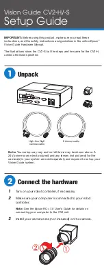
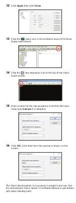
1
Unpack
High-flex GigE
camera cable
Ethernet cable
Note:
Your setup may vary and not all items may be shown above. A
24V power source (not pictured) and any lenses (not pictured) for the
camera(s) in your system are sold separately and required to set up your
Vision Guide system.
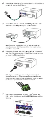
2
Connect the hardware
1
Turn on your robot controller, if necessary.
2
Make sure your computer is connected to your robot
controller.
Note:
See the Epson RC+ 7.0 User’s Guide for details on
connecting your computer to the CV2 unit.
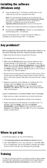
3
Install your camera lens (not included) on the camera.
4
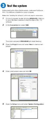
Connect the high-flex GigE camera cable to the camera and
to the
CH1 port on the CV2 unit.
5
Connect the Ethernet cable to the
LAN1 port on the CV2
unit and to the
LAN port on your robot controller.
Note:
If CV2 unit is connected to PC via Ethernet cable, see
online Epson Vision Guide Hardware Manual for details on how
to configure using a hub.
6
Connect your power source to the
DC IN port on the CV2
unit. The CV2 unit powers on. If the CV2 unit does not turn
on, press the power button.
Note:
If you are installing your own 24V power source (not
included), wire it to the 24V power connector included with the
CV2 unit. Be sure to use AWG14–AWG24 wires. For wiring details,
see the online Epson Vision Guide Hardware Manual.
7
Check the lights for proper function. The power and
PoE 1 lights should be on and the
STATUS light should be
flashing.
ERROR
DC IN 19V-24V
CON 1
CH1
1
2
3
4
CH2
CH3
CH4
STATUS TRIGGE
R
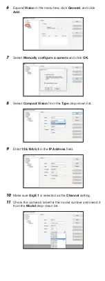
3
Test the system
Before testing the Vision Guide system, make sure the Epson
RC+ 7.0 software is installed on your computer.
Note:
See “Installing the software” on the next page for instructions.
1
On your computer, double-click the
EPSON RC+ 7.0 icon
on your Windows
®
desktop to start the Epson RC+ 7.0
software.
2
In the
Connection list, select USB.
The robot controller’s
PROGRAM light starts flashing.
3
Open the
Project menu and select New to create a test
project.
4
Enter a test project name and click
OK.
5
Open the
Setup menu and select System Configuration.
Vision Guide CV2-H/-S


