background image

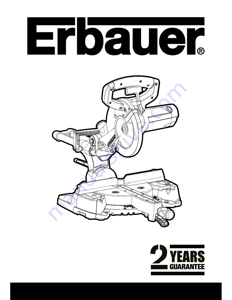
ERBAUER 210MM (8-1/4”) SLIDING COMPOUND MITRE SAW

ERB609MSW  

Original Instructions

Patent Pending 1008829.2

Read instructions fully before operating this tool

(SKU NO 85091 - J1X-KZ9-210J)

Summary of Contents for ERB609MSW

Page 1: ...ERBAUER 210MM 8 1 4 SLIDING COMPOUND MITRE SAW ERB609MSW Original Instructions Patent Pending 1008829 2 Read instructions fully before operating this tool SKU NO 85091 J1X KZ9 210J ...

Page 2: ...ERBAUER 210MM 8 1 4 SLIDING COMPOUND MITRE SAW ...

Page 3: ...months you may return the goods for a full refund or we will repair or replace the goods if you prefer When repair is not practical or identical goods are not available alternative goods of similar specification and quality will usually be provided but failing this you will be offered a partial or full refund depending on the time period since purchase This guarantee specifically excludes losses c...

Page 4: ...pose power tools to rain or wet conditions Water entering a power tool will increase the risk of electric shock d Do not abuse the cord Never use the cord for carrying pulling or unplugging the power tool Keep cord away from heat oil sharp edges or moving parts Damaged or entangled cords increase the risk of electric shock e When operating a power tool outdoors use an extension cord suitable for o...

Page 5: ...d do not allow persons unfamiliar with the power tool or these instructions to operate the power tool Power tools are dangerous in the hands of untrained users e Maintain power tools Check for misalignment or binding of moving parts breakage of parts and any other condition that may affect the power tools operation If damaged have the power tool repaired before use Many accidents are caused by poo...

Page 6: ...fety instructions for all saws Causes and operator prevention of kickback kickback is a sudden reaction to a pinched bound or misaligned saw blade causing an uncontrolled saw to lift up and out of the workpiece toward the operator when the blade is pinched or bound tightly by the kerf closing down the blade stalls and the motor reaction drives the unit rapidly back toward the operator if the blade...

Page 7: ...and close instantly Never clamp or tie the lower guard into the open position If saw is accidentally dropped the lower guard may be bent Raise the lower guard with the retracting handle and make sure it moves freely and does not touch the blade or any other part in all angles and depths of cut b Check the operation of the lower guard spring If the guard and the spring are not operating properly th...

Page 8: ... to determine if it will operate properly and perform its intended function Check for misalignment or binding of moving parts breakage of parts and any other condition that may affect the tool s operation A guard or other part that is damaged should be properly repaired or replaced at a qualified service centre 7 Do not abuse the cord Never use the cord to carry the tools or pull the plug from the...

Page 9: ...adequate lighting of the immediate work area 22 When fitted with laser no exchange with different type of laser is permitted Repairs shall only be carried out by the laser manufacturer or an authorised agent 23 Refrain from removing any cut offs or other parts of the workpiece from the cutting area whilst the machine is running and the saw head is not the rest position 24 Never stand on this tool ...

Page 10: ...is the same as the voltage given on the rating plate The tool is fitted with a two core cable and plug Remove the mains plug from socket before carrying out any adjustment or servicing SPECIFIC SAFETY RULES SYMBOLS Warning Do not operate machine if warning and or instruction labels are missing or damaged Symbol Description V Volts A Amperes Hz Hertz Min 1 Speed Alternating Current No No Load Speed...

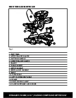
Page 11: ...E SAW Fig 1 1 DUST BAG 2 UPPER BLADE GUARD 3 CUTTING HANDLE 4 LOWER BLADE GUARD 5 BLADE 6 TABLE INSERT 7 MITRE HANDLE 8 BEVEL LOCK HANDLE 9 BASE 10 TURNTABLE 11 LEFT EXTENSION TABLE 12 FENCE 13 HOLD DOWN CLAMP 14 SLIDE CARRIAGE LOCK KNOB 6 1 3 12 10 14 2 4 7 8 9 11 5 13 ...

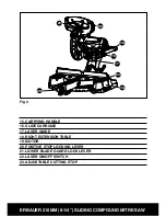
Page 12: ...ITRE SAW 15 CARRYING HANDLE 16 SLIDE CARRIAGE 17 LASER GUIDE 18 RIGHT EXTENSION TABLE 19 MOTOR 20 POSITIVE STOP LOCKING LEVER 21 LOWER BLADE GUARD LOCK LEVER 22 LASER ON OFF SWITCH 23 ADJUSTABLE CUTTING STOP Fig 2 17 15 18 20 21 22 23 16 19 ...

Page 13: ...107 dB A K 3dB A Vibration level 3 384m s2 K 2 5m s2 The declared vibration total value has been measured in accordance with a standard test method and may be used for comparing one tool with another The declared vibration total value may also be used in a preliminary assessment of exposure WARNING The vibration emission during actual use of the power tool can differ from the declared total value ...

Page 14: ...can differ from the declared value depending on the ways in which the tool is used dependant on the following examples and other variations on how the tool is used How the tool is used and the materials being cut or drilled The tool being in good condition and well maintained The use the correct accessory for the tool and ensuring it is sharp and in good condition And the tool is being used as int...

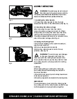
Page 15: ...lide carriage See fig 4 3 Raising the Cutting Head 1 Push down slightly on the switch handle 1 and the lock lever 2 2 Pull out the stop latch knob 3 3 Allow the cutting head to rise to the up position See fig 5 Warning To avoid injury and damage to the saw transport and store the mitre saw with the cutting head locked in the down position Never use the stop latch to hold the cutting head in a down...

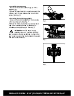
Page 16: ... 5 Installing the hold down clamp 1 Loosen the lock knob 1 from the rear side of the saw base 2 See fig 7 2 Place the hold down clamp assembly 3 in one of the mounting holes 4 See fig 8 3 Tighten the lock knob 1 See fig 7 Warning Always check clamp position does not interfere with any saw operation Before switching on lower the saw head to ensure the clamp clears the guard and saw head assembly Fi...

Page 17: ... during any cutting operation Support the saw on a level work surface Bolt or clamp the saw to its support Mounting instructions 1 For stationary use place the saw in the desired location directly on a workbench where there is room for handling and proper support of the workpiece The base of the saw has four mounting holes Bolt the base of the mitre saw 1 to the work surface 5 using the fastening ...

Page 18: ... fig 11 4 Release the lower blade guard by operating the blade guard handle and rotate the guard into its upper position 5 Locate the arbor lock 1 See fig 12 6 Hold the guard in position with your thumb and press the arbor lock gently with a finger See fig 13 Rotate the blade using the correct sized hex key inserted into the arbor bolt See fig 14 until positive location is felt 7 Keeping the arbor...

Page 19: ...nterclockwise direction See fig 15 IMPORTANT Make sure the flats of the blade collars are engaged with the flats on the arbor shaft 4 Place the hex key into the arbor bolt 5 Press the arbor lock holding gently while turning the blade counterclockwise When arbor lock engages continue to press it in firmly while tightening the arbor bolt securely See fig 14 Note Do not press arbor lock when blade is...

Page 20: ... switch must be turned on for the laser line to show See fig 16 Warning AVOID DIRECT EYE CONTACT Laser radiated when laser guide is turned on Avoid direct eye contact Always unplug the mitre saw from power source before making any adjustments Laser Warning Label Max output 1mW Wavelength 630 670nm EN 60825 1 A1 2007 Laser radiation do not stare into beam Class 2 Laser Product Puissance Note All th...

Page 21: ...o the laser casing could result See fig 17 18 B Adjusting the Angle of the Laser Guide 1 Loosen the single screw on the RH side of the laser housing a turn 2 Turn the laser element in the desired direction to adjust the laser angle 3 Retighten the adjustment screw C Aligning the Laser Beam 1 Use the two adjusting screws on the LH side of the laser housing 2 Adjust both screws until laser alignment...

Page 22: ...quare 2 on the mitre table with the ruler against the table and the heel of the square against the saw blade 3 If the blade is not 90 0 square with the mitre table 5 loosen the bevel lock handle 1 tilt the cutting head to the left loosen the locknut 4 on the bevel angle adjustment bolt 3 and use an hex key to adjust the socket headed stop bolt 3 depth in or out to increase or decrease the bevel an...

Page 23: ...loosen the locknut 2 on the bevel angle adjustment bolt 3 and use an hex key to adjust the stop bolt 3 depth in or out to increase or decrease the bevel angle 4 Tilt the cutting arm to the left to 45 bevel and recheck for alignment 5 Repeat steps 1 through 4 until the blade is at 45 to the mitre table 6 Tighten bevel lock handle 1 and locknut 2 when alignment is achieved See fig 21 5 Bevel Setting...

Page 24: ...ve stops at 0 15 22 5 31 6 and 45 These positive stops position the blade at the desired angle quickly and accurately Follow the process below for quickest and most accurate adjustments 1 Unlock the mitre table by turning the mitre handle 1 counterclockwise 2 Move the turntable while lifting up on the positive stop locking lever 2 to align the indicator 3 to the desired degree measurement 3 If the...

Page 25: ...g the upper arm in that position turn the stop knob 1 until it touches the stop plate 2 3 Recheck the blade depth by moving the cutting head front to back through the full motion of a typical cut along the control arm See fig 26 11 Adjusting cutting depth The maximum depth travel of the cutting head was set at the factory Check to see that the blade does not extend more than 6 35 mm below the tabl...

Page 26: ...oss of power that will overheat the motor If your mitre saw does not operate when plugged into an outlet have a professional electrician check the power supply Warning Avoid accidental starting Make sure the switch is in the OFF position before plugging the mitre saw into a power outlet 3 Body and Hand position Warning Never place hands near the cutting area Proper positioning of your body and han...

Page 27: ... your saw If the blade doesn t stop within approximately 8 seconds wait for the blade to stop unplug the saw and contact customer service To turn saw on Push down the lock lever 1 and squeeze the trigger switch 2 to turn the mitre saw ON Release the trigger switch to turn the saw OFF See fig 28 5 Sliding carriage system 1 For chop cutting operations on small workpieces slide the cutting head assem...

Page 28: ...stop locking lever and tighten the mitre handle The table is now locked at the desired angle Positive stops are provided at 0 15 22 5 31 6 and 45 See fig 30 IMPORTANT Always tighten the mitre table lock handle before performing every cutting operation 7 Bevel cut 1 When a bevel cut is required loosen the bevel lock handle 1 by turning it clockwise 2 Tilt the cutting head to the desired angle as sh...

Page 29: ...g 32 9 Slide cutting wide boards up to 233 mm wide Warning To avoid injury Never pull the cutting head assembly and spinning blade toward you during the cut The blade may try to climb up on the top of the workpiece causing the cutting assembly and spinning blade to kick back forcefully The cutting head assembly should be drawn back completely then pushed forward when sawing Let the blade reach ful...

Page 30: ... as shown Warning Do not position workpiece incorrectly or try to cut the workpiece without the support of the fence See fig 34 This will cause the blade to bind and could result in personal injury 11 Satellite workpiece support Incorporated into the LH side of the machine base is a removable satellite stand Use this stand to help support long pieces of material To remove the satellite stand press...

Page 31: ...ps See fig 36 To deploy the stop outboard 1 Slide the sprung loaded lock 2 forwards 2 Whilst holding the release lock pull the stop 1 from its stored position upwards and to the right The stop will deploy to the outboard position 3 Slide the release lock 2 backwards to lock the stop position 4 To stow away reverse the above steps See fig 37 Adjusting the stop plate Deploy the stop plate as outline...

Page 32: ...r is applied to the saw 15 Cutting crown moulding Your compound mitre saw is suited for the difficult task of cutting crown moulding To fit properly crown moulding must be compound mitred with extreme accuracy The two surfaces on a piece of crown moulding that fit flat against the ceiling and wall are at angles that when added together equal exactly 90 See fig 39 40 Most crown moulding has a top r...

Page 33: ...IGHT 31 6 0 3 RIGHT side is finished piece Fig 42 W 27 ERBAUER 216MM 8 SLIDING MITRE SAW Bevel Mitre Settings Settings for standard crown molding lying flat on compound mitre saw table Note The chart below references a compound cut for crown molding ONLY WHEN THE ANGLE BETWEEN THE WALLS EQUALS 90 KEY BEVEL SETTING MITRE SETTING TYPE OF CUT Inside corner Left side IL 33 9 31 6 Right 1 Position top ...

Page 34: ... plastic cap 1 on the side of the motor 2 Remove the cap cautiously because it is spring loaded Then pull out the brush and replace Replace for the other side To reassemble reverse the procedure The ears on the metal end of the assembly go in the same hole the carbon part fits into Tighten the cap snugly but do not overtighten See fig 43 Note To reinstall the same brushes first make sure the brush...

Page 35: ...es Lubrication All the motor bearings in this tool are lubricated with a sufficient amount of high grade lubricant for the life of the unit under normal operating conditions therefore no further bearing lubrication is required Lubricate the following as necessary Chop pivot Apply light machine oil Central pivot of plastic guard Use light household oil sewing machine oil on metal to metal or metal ...

Page 36: ...the voltage given on your power tool matches the supply voltage The power tool is supplied with a fitted plug however if you should need to fit a new plug follows the instruction below IMPORTANT The wire in the mains lead are coloured in accordance with the following code Blue Neutral Brown Live The wire that is coloured blue must be connected to the terminal that is marked with the letter N The w...

Page 37: ...6 EC and 2003 108 EC Waste Electrical and Electronic Equipment WEEE Standards and technical specifications referred to EN55014 1 EN55014 2 A2 EN61000 3 2 EN61000 3 11 EN61029 1 EN61029 2 9 EN60825 1 Authorised Signatory Date 25 06 2010 Signature ECLARATION OF ONFORMITY 7E MPORTER 3CREWlX IRECT TD EAD VENUE OUNDSTONE USINESS 0ARK 9EOVIL 24 ECLARE THAT THE PRODUCT 42 3 7 3 OMPLIES WITH THE ESSENTIAL...

Page 38: ...ERBAUER 210MM 8 1 4 SLIDING COMPOUND MITRE SAW ...

Page 39: ...ERBAUER 210MM 8 1 4 SLIDING COMPOUND MITRE SAW ...

Page 40: ...ERBAUER 210MM 8 1 4 SLIDING COMPOUND MITRE SAW ...

Reviews: