background image

These INSTRUCTIONS are for experienced operators. If you are not fully familiar with the principles of operation and safe practices for arc
welding equipment we urge you to read our booklet Precautions and Safe Practices for Arc Welding, Cutting and Gouging, Form 52-529.
Do NOT permit untrained persons to install, operate or maintain this equipment. Do NOT attempt to install or operate this equipment until
you have read and fully understand these instructions. If you do not fully understand these instructions contact your supplier for further
information. Be sure to read the Safety Precautions on page 2 before installing or operating this equipment.

INSTRUCTION MANUAL

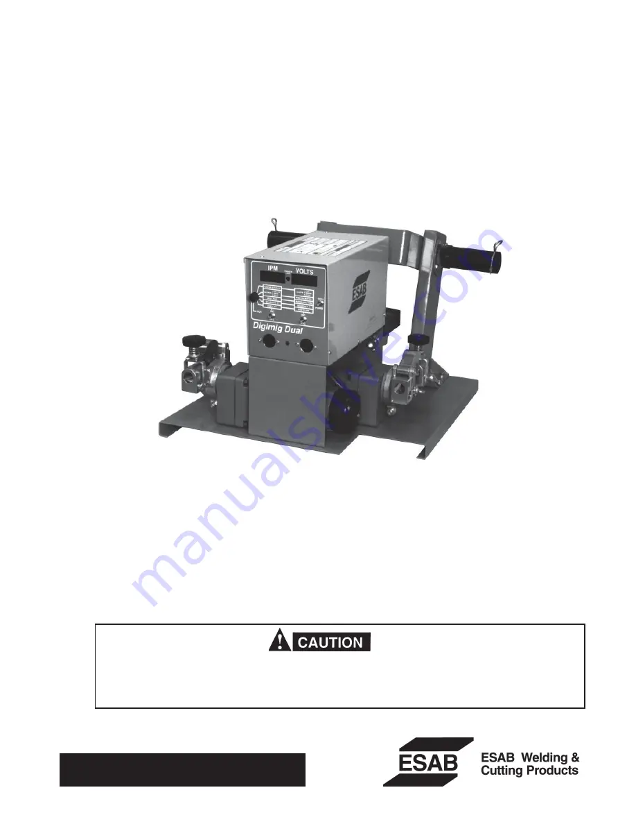
DIGIMIG DUAL WIRE FEEDER

This manual provides installation and operating instructions for the following wire feeder(s):

ESAB Part No. 30912 — 115V, 1-Phase, 50/60 Hertz. (Starting with Serial No. #####)
L-TEC Part No. ????? — 115V, 1-Phase, 50/60 Hertz. (Starting with Serial No. #####)

F-14-489-C

Sept., 2003

Be sure this information reaches the operator.
You can get extra copies through your supplier.

Summary of Contents for Digimig Dual

Page 1: ...lly understand these instructions If you do not fully understand these instructions contact your supplier for further information Be sure to read the Safety Precautions on page 2 before installing or operating this equipment INSTRUCTION MANUAL DIGIMIG DUAL WIRE FEEDER This manual provides installation and operating instructions for the following wire feeder s ESAB Part No 30912 115V 1 Phase 50 60 ...

Page 2: ... of the manufacturer The user of this equipment shall have the sole responsibility for any malfunction which results from improper use faulty maintenance damage improper repair or alteration by anyone other than the manufacturer or a service facility designated by the manufacturer TABLE OF CONTENTS SECTION TITLE PAGE PARAGRAPH SECTION 1 DESCRIPTION 5 1 1 General 5 1 2 Scope 5 1 3 Specifications 5 ...

Page 3: ...ubstances on the workpiece which might produce flammable or toxic vapors Do not do hot work on closed containers They may explode 4 Have fire extinguishing equipment handy for instant use such as a garden hose water pail sand bucket or portable fire extinguisher Be sure you are trained in its use 5 Do not use equipment beyond its ratings For example overloaded welding cable can overheat and create...

Page 4: ...mes Never strike an arc on a cylinder 5 For additional information refer to CGA Standard P 1 Precautions for Safe Handling of Compressed Gases in Cylinders which is available from Compressed Gas Association 1235 Jefferson Davis Highway Arlington VA 22202 EQUIPMENT MAINTENANCE Faulty or improperly maintained equipment can cause injury or death Therefore 1 Always have qualified personnel perform the...

Page 5: ...orsoftwiresfrom 030 in to 1 16 in in diameter and flux cored wires from 035 in to 5 64 in in diameter Rate of wire feed 20 999 ipm ispreciselycontrolledbyusingaclosed loop J governor digitalfeedbackcircuitthatemploysanopticaltachometer tomonitorthemotorspeed Arcvoltageregulationisalso controlled by a closed loop digital feedback circuit that monitors the arc voltage and automatically adjusts the p...

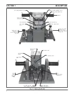
Page 6: ...LEFT INC DEC SW 6 POS ROTARY SELECTOR SW TORCH ACCY LEFT SUPPORT ASSY EH 10 MOTOR GEAR TACH UNIT TORCH ACCY RIGHT SUPPORT ASSY EH 10 MOTOR GEAR TACH UNIT RIGHT INC DEC SW RIGHT DIGITAL READOUT VOLTS INCH PURGE RESET SW SPINDLE Fig 1 1 Digimig Dual Feeder SECTION 1 DESCRIPTION RIGHT TORCH RECPT LEFT TORCH RECPT LEFT TORCH GAS SOL CONNECTION RIGHT TORCH GAS SOL CONNEC TION ...

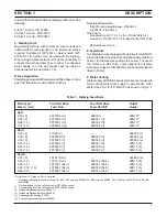
Page 7: ...onnect the torches water hose to either a continuous water supply or to the wire feeder base by using an optional water kit see Section 1 5 D Gas Regulation Shieldinggasregulator flowmeterandfittedhosetobring gas from flowmeter to wire feeder Such as Table 1 Digimig Feed Rolls Wire Type Two Roll Drive Four Roll Drive Outlet Size In mm Feed Roll Feed Roll Kit Guide Soft 030 8 2075304 U 999320 29N13...

Page 8: ... b Wire Wiper Holder P N 598763 F Wire Spool Spacer P N 948378 Enables the use of a 8 in diameter spool of welding wire with spindle assembly on the Digimig wire feeder G WC 9 Coolant Circulator P N 33540 is used for water cooled torch operation and is designed to be freestanding inaconvenientlocationnearthetorch A four gallon capacity tank provides 1 0 gal min 50 psi using 115 volts 50 60 Hertz 1...

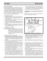
Page 9: ...ON 2 1 GENERAL Proper installation can contribute materially to the sat isfactory and trouble free operation of the wire feeder It is suggested that each step in this section be carefully studied and followed as closely as possible After checking to be sure you have all required compo nents and accessories see Section 1 proceed as follows with reference to Figs 2 1 2 2 Interconnec tion Diagrams To...

Page 10: ...e will permit the spool to over run causing the wire to kink and tangle 5 Thread the wire on to the accessory support assem bly as described in E following 6 When wire coils are to be used instead of spools mount wire reel on spindle as through it were a spool see 1 and 3 above Remove thumbnuts and cover plate from reel Remove coil from its package but do not remove its binding wires Slide coil on...

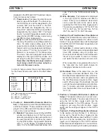
Page 11: ...ontrol NOTE Immediately after the control has been turned on various numerical code data e g Pro gram I D Power Source and Slope will appear in the IPM and VOLTS display windows for 4 seconds After this delay the preset weld pa rameters for the last torch used will be shown This is further described in the General Trouble shooting Section 2 Run Set Key This key operated switch must be in the SET p...

Page 12: ...d designated by the numeral 1 3 or 6 see Rotary Switch Item 6 a pair of numbers represent WIRE DIAMETER sizes which are programmed for selection as follows 30 35 45 52 or 63 see Rotary Switch Item 6 shielding gas POSTFLOW from 1 to 99 9 sec onds in one tenth of a second increments manual BURNBACK time Manually adjustable burnback time period which when preset will override the automatic adaptive a...

Page 13: ...3 is for the 5000 aluminum series of wires 2 Wire Diameter This parameter is displayed in the right VOLTS window and offers a choice of five 5 wire diameter sizes which can be used for each torch and is set by operating the VOLTS Inc Dec toggle switch The wire sizes available are 30 for 030 dia 35 for 035 dia 45 for 045 dia 52 for 052 dia and 63 for 063 dia wires c Position3 SpotTime BurnbackTime ...

Page 14: ...without energizing the welding circuit It also allows you to look at a pair of numbers that will SECTION 3 OPERATION have a bearing on the quality of starts as explained in Section 3 4 B 5 2 After starting the welding sequence if an abort shutdown condition occurs indicated by a flashing digital display the RESET posi tion can be actuated and the control automati cally resets for a new start 3 Act...

Page 15: ...cteristic set on your power source One of three slope designations will ap pear in the VOLTS window 1 for Flat 3 for Medium or 6 for Steep Slope Make sure the feeder slope number matches the slope se lected at the power source see section 3 2 6 a 5 You can also select optional Trigger Lock In see Section 3 2 3A however remember when added on both torches are locked in B PROGRAM FIRST e g RIGHT TOR...

Page 16: ... such as cable length type of torch used water ver sus gas cooled shielding gas condition of weldment type of welding wire etc To mini mize the effect of these variables a simple adjustment will allow you to increase or de SECTION 3 OPERATION crease the initial arc striking voltage to optimize starting The following procedure 5 A allows you to make this correction 5A Setting Controller For Optimum...

Page 17: ... metal to metal contact between the wire feeder chassis and a metal surface connected in any way to a welding ground With such contact a poor welding ground connection may create a difference In potential that sends part of the welding current through the safety ground wiring resulting inburnoutofthatwiringand ordamagetothefeeder circuitry Ifthesafetygroundburnsout theoperator may be exposed to 11...

Page 18: ...s decimals etc or are completely incorrect in relation to your settings the memory must be cleared This condition might occur after a bad lightning storm extremely bad power line surge etc To clear the memory do the following a Place the Run Set key switch in its SET position b Turn off the unit s 115 volt Power switch c Using one hand hold both of the Inc Dec toggle switches in their INC position...

Page 19: ...l Shut Down either preset VOLTS or IPM displays will flash The control will flash the param eter VOLTS or IPM that cannot be maintained If this condition occurs the respective speed and voltage conditions servos need to be checked for each of the four 4 possible schedules and if neces sary readjusted as follows 1 This symptom can of occur as a result of either or all of the following the factory s...

Page 20: ...o this setting will override the servo b Place the Panel Remote switch on the power source in PANEL position c Make a weld by controlling the arc voltage directly from the power source potentiometer d If a weld can be made with good control over power source voltage a problem exists either in the inter connecting voltage control cable or in the Digimig control e Check the control wires in the inte...

Page 21: ...21 SECTION 4 TROUBLESHOOTING Fig 4 1 Schematic Diagram Dual Digimig 30914 L ...

Page 22: ......

Page 23: ...t or dirt Cleaning is best accomplished by regularly blowing off these parts with dry compressed air This should be done once for every eight hours of operating time more often if necessary B LUBRICATION OF DIGITAL MOTOR GEAR UNIT The EH 10A motor gear digital unit is lubricated with a heavy duty grease when assembled at the factory and should not require further lubrication unless disas sembled I...

Page 24: ...H 10A DIGITAL MOTOR GEAR UNIT ASSY 679777 See Fig 6 BASE 678806 LEFT TORCH J4 RECEPTACLE 182W64 C16 CAPACITOR 672348 2 ACCESSARY SUPPORT ASSY 2 ROLL DRIVE See Fig 8 49V51 FRONT CONTROL SUPPORT 30917 SW1 3 5 SWITCH 950087 LIFTING BRACKET 30916 CONTROL ASSY 30913 see Fig 7 6 POS ROTARY SW 679914 Fig 6 1 DigiMig Dual Wire Feeder P N 30912 Front View ...

Page 25: ...LEVILLE WASHER 950783 Replace decal if it becomes excessively worn or lost when replacing panel s Recommended Spare Parts Replacement key for Run Set SW 32778 J1 RECEPTACLE 950762 19 pin C20 CAPACITOR 1uf 500 V CB CIRCUIT BREAKER 950874 MSL POWER ON OFF SW 634517 STRAIN RELIEF 96W76 RUN SET SW 950956 2 GAS INLET CONNECTION 74S76 2 GAS SOLENOID VALVE 2062305 2 GAS BULKHEAD ADAPTOR 58V58 VR VOLTAGE ...

Page 26: ...19731 BRUSH HOLDERzz zGASKET SEAL KIT 20542 Includes those items market with Fig 6 3 EH 10A Motor Gear Unit Parts Breakdown TACH P C B D 675429 2 Screw 61324746 Gear Case Lubricated with Texac Multifak Grease 11 6 2 370 93 6251 MOTOR END HOUSING Ref 54 LG 10 2 875 50 DP MIN VENTPLUG 3 25 2 000 5 16 18 UNC 2B 2 86 25 4 010 SQ 2 25 1 375 1 375 25 END VIEW w COVER REMOVED 63 MIN DEPTH MTR LEAD TACH D...

Page 27: ...P4 To MPU P2 CABLE ASSY 677938 For Replacement Battery on I O Board order P N 951733 I 0 P C BOARD ASSY 674956 CTR1 BOT CONT TRANSFORMER 950088 Replace decal if it becomes excessively worn or lost Recommended Spare Parts CTR2 TOP CONT TRANSFORMER 994303 T1 20 PT Terminal Strip 950182 NOTE The heat sinks of the J gov board are electrically hot Do NOT touch or ground while unit is energized DISPLAY ...

Page 28: ...INER 58N24 FORK 49V43 Outlet guide And Wiper Holder Not Included in Assembly Part No 49V51 INCLUDES SUPPLIED WIRE OUTLET GUIDE See Table 1 WIRE OUTLET GUIDE INSERT SPINDLE 948258 D TYPE WASHER 948254 SCREW 5 16 18 x 2 HAIR PIN CLIP 634347 WASHER 948256 SUPPORT 948257 SPRING 948253 2 BRAKE PAD 948255 4 359 DIA HOLE ON 3 DIA D C REEL Ref Hair Pin Clip WIRE REEL 995570 Includes REEL 995568 COVER 9955...

Page 29: ...29 NOTES ...

Page 30: ...30 NOTES ...

Page 31: ...e upper corners of the control panel on the power source and open the control panel 4 Install the 14 pin receptacle into the front panel from the inside and secure with the four screws provided with the kit 5 Locate the control leads access grommet to the control panel Insert the connector from the 14 pin receptacle through this grommet Route the leads along with the other control leads and se cur...

Page 32: ... Warranty Returns Authorized Repair Stations Welding Equipment Troubleshooting C TECHNICAL SERVICE Telephone 800 ESAB 123 Fax 843 664 4452 Hours 8 00 AM to 5 00 PM EST Part Numbers Technical Applications Specifications Equipment Recommendations D LITERATURE REQUESTS Telephone 843 664 5562 Fax 843 664 5548 Hours 7 30 AM to 4 00 PM EST E WELDING EQUIPMENT REPAIRS Telephone 843 664 4487 Fax 843 664 5...

Reviews: